

Page 1
INSTRUCTIONS-PARTS LIST
307912
This manual contains important
warnings and information.
READ AND KEEP FOR REFERENCE.
INSTRUCTIONS
Model PRO 3500sc
Electrostatic Air Spray Gun
65 kV, MANUAL GUN
100 psi (7 bar, 0.7 MPa) Maximum Working Pressure
Part No. 222300, Series B
With Two-Finger Trigger
Part No. 222600, Series B
With Four-Finger Trigger
Rev. AC
Part No. 222300 shown
NOTE: Any modification of genuine Graco parts or replacement of parts with non-Graco parts will void agency approvals.
U.S. PATENT NO. 4,290,091; 4,219,865; 4,497,447; 4,462,061; 4,660,774 ; D313,064; 4,978,075
Patented 1986, 1987 Canada
Brevete 1986, 1987
U.K. PATENT NO. 2,147,158; 2,142,559B; 2,140,327B
French Patent No. 89 16305
Other U.S. and Foreign Patents Pending
GRACO INC. P.O. BOX 1441 MINNEAPOLIS, MN 55440–1441
COPYRIGHT 1989, GRACO INC.
Graco Inc. is registered to I.S. EN ISO 9001
06443
Page 2
Table of Contents
Symbols 2. . . . . . . . . . . . . . . . . . . . . . . . . . . . . . . . . . . . . .
Warnings 3. . . . . . . . . . . . . . . . . . . . . . . . . . . . . . . . . . . . .
Introduction 5. . . . . . . . . . . . . . . . . . . . . . . . . . . . . . . . . .
How the Electrostatic Air Spray Gun Works 5. . . .
Installation 5. . . . . . . . . . . . . . . . . . . . . . . . . . . . . . . . . . .
Installing the System 5. . . . . . . . . . . . . . . . . . . . . . . .
Warning Signs 5. . . . . . . . . . . . . . . . . . . . . . . . . . . . .
Ventilate the Spray Booth 5. . . . . . . . . . . . . . . . . . . .
Non-hazardous Area 6. . . . . . . . . . . . . . . . . . . . . . . .
Hazardous Area 6. . . . . . . . . . . . . . . . . . . . . . . . . . . .
Connect the Air Line 7. . . . . . . . . . . . . . . . . . . . . . . .
Connect the Exhaust Tube 7. . . . . . . . . . . . . . . . . . .
Connect the Fluid Line 7. . . . . . . . . . . . . . . . . . . . . . .
Ground the System 8. . . . . . . . . . . . . . . . . . . . . . . . .
Check the Electrical Grounding 9. . . . . . . . . . . . . . .
Operation 11. . . . . . . . . . . . . . . . . . . . . . . . . . . . . . . . . . . .
Pressure Relief Procedure 11. . . . . . . . . . . . . . . . . .
Filter the Fluid 11. . . . . . . . . . . . . . . . . . . . . . . . . . . . .
Operating Checklist 11. . . . . . . . . . . . . . . . . . . . . . . .
Selecting a Fluid Nozzle and Air Cap 12. . . . . . . . .
Operating the Spray Gun 12. . . . . . . . . . . . . . . . . . .
Shutdown 14. . . . . . . . . . . . . . . . . . . . . . . . . . . . . . . . .
Service 22. . . . . . . . . . . . . . . . . . . . . . . . . . . . . . . . . . . . . .
Prepare the Gun for Service 22. . . . . . . . . . . . . . . . . . . .
Air Cap/Nozzle/Resistor Stud Replacement 22. . . . . .
Electrode Replacement 23. . . . . . . . . . . . . . . . . . . . . . . .
Barrel Removal 24. . . . . . . . . . . . . . . . . . . . . . . . . . . . . . .
Fluid Packing Removal 25. . . . . . . . . . . . . . . . . . . . . . . .
Fluid Packing and Needle Repair 26. . . . . . . . . . . . . . . .
Power Cartridge Replacement 27. . . . . . . . . . . . . . . . . .
Turbine Alternator Replacement 28. . . . . . . . . . . . . . . .
Barrel Installation 28. . . . . . . . . . . . . . . . . . . . . . . . . . . . . .
Fan Air Adjustment Valve Repair 29. . . . . . . . . . . . . . . .
Fluid Adjustment Assembly Repair 30. . . . . . . . . . . . . . .
Air Trigger Valve Repair 31. . . . . . . . . . . . . . . . . . . . . . . .
Atomizing Air Valve Removal and Replacement 31. . .
ES ON-OFF Valve Repair 32. . . . . . . . . . . . . . . . . . . . . .
Parts 34. . . . . . . . . . . . . . . . . . . . . . . . . . . . . . . . . . . . . . . .
Accessories 36. . . . . . . . . . . . . . . . . . . . . . . . . . . . . . . . .
Technical Data 39. . . . . . . . . . . . . . . . . . . . . . . . . . . . . . .
The Graco Warranty and Disclaimers 40. . . . . . . . . .
Graco Phone Number 40. . . . . . . . . . . . . . . . . . . . . . . .
Maintenance 14. . . . . . . . . . . . . . . . . . . . . . . . . . . . . . . . .
Daily Care and Cleaning 14. . . . . . . . . . . . . . . . . . . .
Clean the Air Cap and Fluid Nozzle 15. . . . . . . . . .
Flush the Spray Gun 15. . . . . . . . . . . . . . . . . . . . . . .
Troubleshooting 16. . . . . . . . . . . . . . . . . . . . . . . . . . . . .
Spray Pattern Troubleshooting 16. . . . . . . . . . . . . . .
Gun Operation Troubleshooting 17. . . . . . . . . . . . . .
Electrical Troubleshooting 18. . . . . . . . . . . . . . . . . . .
Electrical Tests 19. . . . . . . . . . . . . . . . . . . . . . . . . . . . . . .
Test Gun Resistance 19. . . . . . . . . . . . . . . . . . . . . . .
Test Power Supply Resistance 20. . . . . . . . . . . . . . .
Test Resistor Stud Resistance 20. . . . . . . . . . . . . . .
Symbols
Warning Symbol
WARNING
This symbol alerts you to the possibility of serious
injury or death if you do not follow the instructions.
Caution Symbol
CAUTION
This symbol alerts you to the possibility of damage to
or destruction of equipment if you do not follow the
corresponding instructions.
2 307912
Page 3
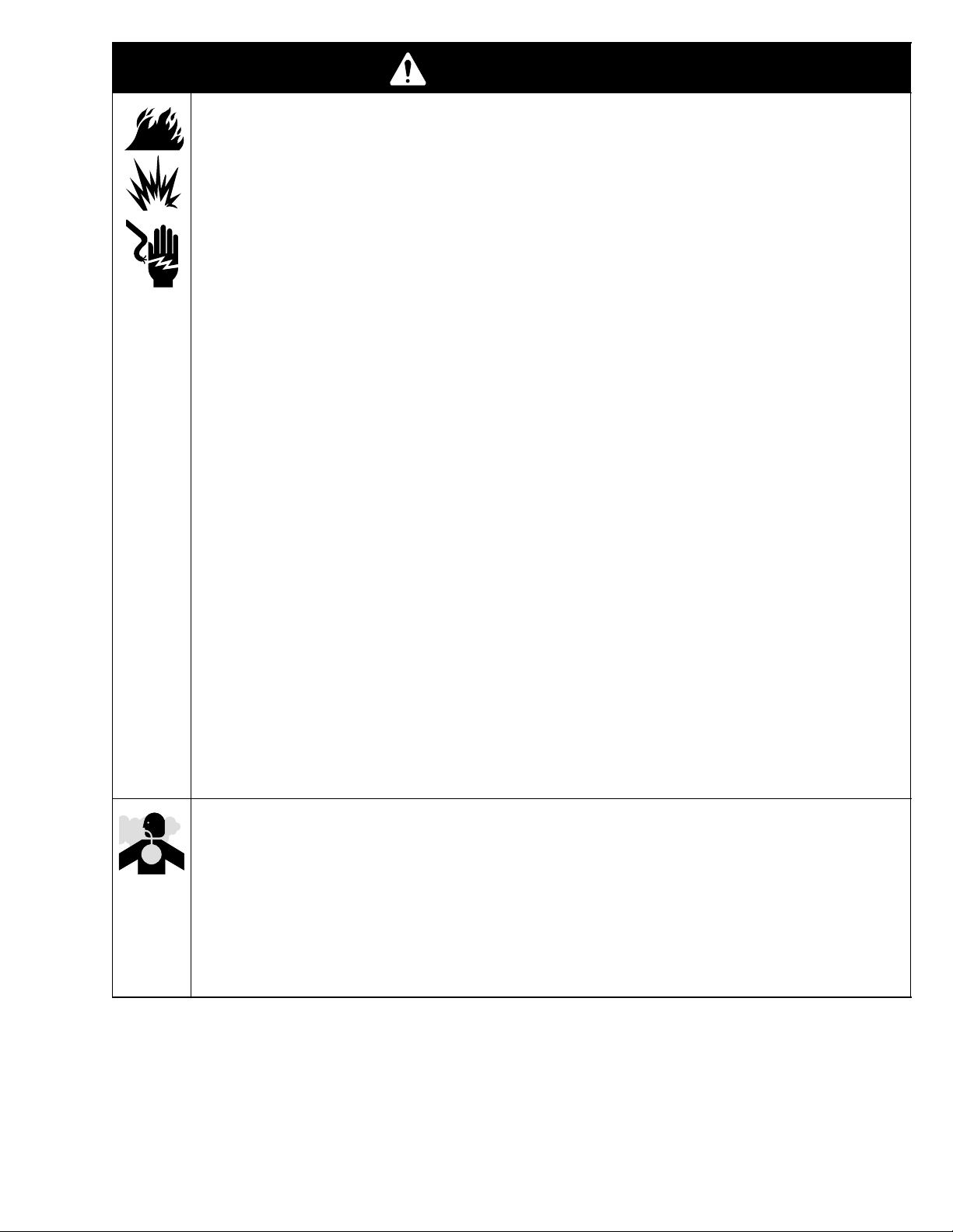
WARNING
FIRE, EXPLOSION, AND ELECTRIC SHOCK HAZARD
Improper grounding, poor air ventilation, open flames, or sparks can cause a hazardous condition and
result in a fire, explosion, or electric shock.
Electrostatic equipment must be used only by trained, qualified personnel who understand the
requirements stated in this instruction manual.
Ground the equipment, personnel in or close to the spray area, the object being sprayed, and all
other electrically conductive objects in the spray area. See Ground the System on page 8.
Check the spray gun resistance daily. See Test Gun Resistance, page 19.
If there is any static sparking while using the equipment, stop spraying immediately. Identify and
correct the problem.
Provide fresh air ventilation to avoid the buildup of flammable or toxic vapors. Interlock the gun
turbine air supply to prevent operation of the power supply unless the ventilating fans are on. See
Ventilate the Spray Booth on page 5.
When cleaning, flushing, or purging electrostatic equipment, use solvents that comply with your
local regulations. For countries following the U.S. National Fire Protection Association (NFPA) 33
requirements, use solvents with a flash point higher than 100 F (38 C) or a solvent normally
used in spray operations. For European Countries complying with EN 50053, use solvents with a
flash point as high as possible and higher than the ambient temperatures.
Use only non-sparking tools to clean residue from the booth and hangers.
Do not flush the system with the gun electrostatics turned on.
Do not turn on the gun electrostatics until all solvent is removed from the system.
Extinguish all open flames or pilot lights in the spray area.
Keep the spray area free of debris, including solvent, rags, and gasoline.
Do not store any flammable fluids in the spray area.
Do not turn on or off any light switch in the spray area while operating or if fumes are present.
Do not smoke in the spray area.
Do not operate a gasoline engine in the spray area.
TOXIC FLUID HAZARD
Hazardous fluids or toxic fumes can cause a serious injury or death if splashed in the eyes or on the
skin, swallowed, or inhaled.
Know the specific hazards of the fluid you are using. Read the fluid manufacturer’s warnings.
Store hazardous fluid in an approved container. Dispose of the hazardous fluid according to all
local, state, and national guidelines.
Wear appropriate protective clothing, gloves, eyewear, and respirator.
Warnings are continued on the next page.
307912 3
Page 4

WARNING
PRESSURIZED EQUIPMENT HAZARD
Spray from the gun, hose leaks, or ruptured components can splash fluid in the eyes or on the skin
and cause a serious injury.
Do not point the spray gun at anyone or any part of the body.
Do not stop or deflect fluid leaks with your hand, body, glove, or rag.
Follow the Pressure Relief Procedure on page 11 whenever you: are instructed to relieve the
pressure; stop spraying; clean, check, or servicing the equipment; and install or clean the fluid
nozzles.
Tighten all the fluid connections before operating the equipment.
Check the hoses, tubes and couplings daily. Replace worn, damaged, or loose parts immediately.
Permanently coupled hoses cannot be repaired; replace the entire hose.
EQUIPMENT MISUSE HAZARD
INSTRUCTIONS
Equipment misuse can cause the equipment to rupture, malfunction, or start unexpectedly and result
in a serious injury.
This equipment is for professional use only.
Read all the instruction manuals, tags, and labels before operating the equipment.
Use the equipment only for its intended purpose. If you are uncertain about usage, call your Graco
distributor.
Do not alter or modify this equipment. Use only genuine Graco parts and accessories.
Check the equipment daily. Repair or replace worn or damaged parts immediately.
Do not exceed the maximum working pressure of the lowest rated system component. This equip-
ment has a 100 psi (7 bar, 0.7 MPa) maximum working air and fluid pressure.
Use fluids that are compatible with the equipment wetted parts. See the Technical Data section of
all the equipment manuals. Read the fluid manufacturer’s warnings.
Route the hoses away from traffic areas, sharp edges, moving parts, and hot surfaces. Do not
expose Graco hoses to temperatures above 180F (82C) or below –40F (–40C).
Do not use the hoses to pull equipment.
Wear hearing protection when operating this equipment.
Comply with all applicable local, state, and national fire, electrical, and other safety regulations.
4 307912
Page 5
Introduction
How the Electrostatic Air Spray Gun Works
The air hose supplies air to the spray gun. Part of the
air operates the turbine and the rest of the air atomizes
the fluid being sprayed. The turbine generates power,
which is converted by the power cartridge, to supply
high voltage current to the gun’s ionizing electrode.
Installation
Installing the System
WARNING
FIRE, EXPLOSION, AND
ELECTRIC SHOCK HAZARD
Installing and servicing this equipment
requires access to parts which may
cause electric shock or other serious
injury if work is not performed properly.
Do not install or service this equip-
ment unless you are trained and
qualified.
Be sure your installation complies with National,
State and Local codes for the installation of
electrical apparatus in a Class I, Group D
Hazardous Location.
The pump supplies fluid to the hose and gun, where
the fluid is electrostatically charged as it passes the
electrode. The charged fluid is attracted to the
grounded workpiece, wrapping around and evenly
coating all surfaces.
Warning Signs
Mount warning signs in the spray area where they can
easily be seen and read by all operators. An English
Warning Sign is provided with the gun. Additional
English, French, German, and Spanish signs are
available at no charge. See Accessories to order
them.
Ventilate the Spray Booth
WARNING
FLAMMABLE OR TOXIC
VAPOR HAZARD
Provide fresh air ventilation to avoid the
buildup of flammable or toxic vapors. Do
not operate the gun unless ventilation
fans are operating.
Comply with all applicable local, state, and
national fire, electrical, and other safety regulations.
Fig. 1 shows a typical electrostatic air spray system.
It is not an actual system design. The particular type
and size system for your operation must be custom
designed for your needs. For assistance in designing a
system, contact your Graco distributor.
Electrically interlock the gun air supply with the ventilators to prevent gun operation without ventilating fans
operating. Check and follow all National, State, and
Local codes regarding air exhaust velocity
requirements.
NOTE: High velocity air exhaust will decrease the
operating efficiency of the electrostatic system. Air
exhaust velocity of 100 ft/min (31 linear meters/minute)
should be sufficient.
307912 5
Page 6
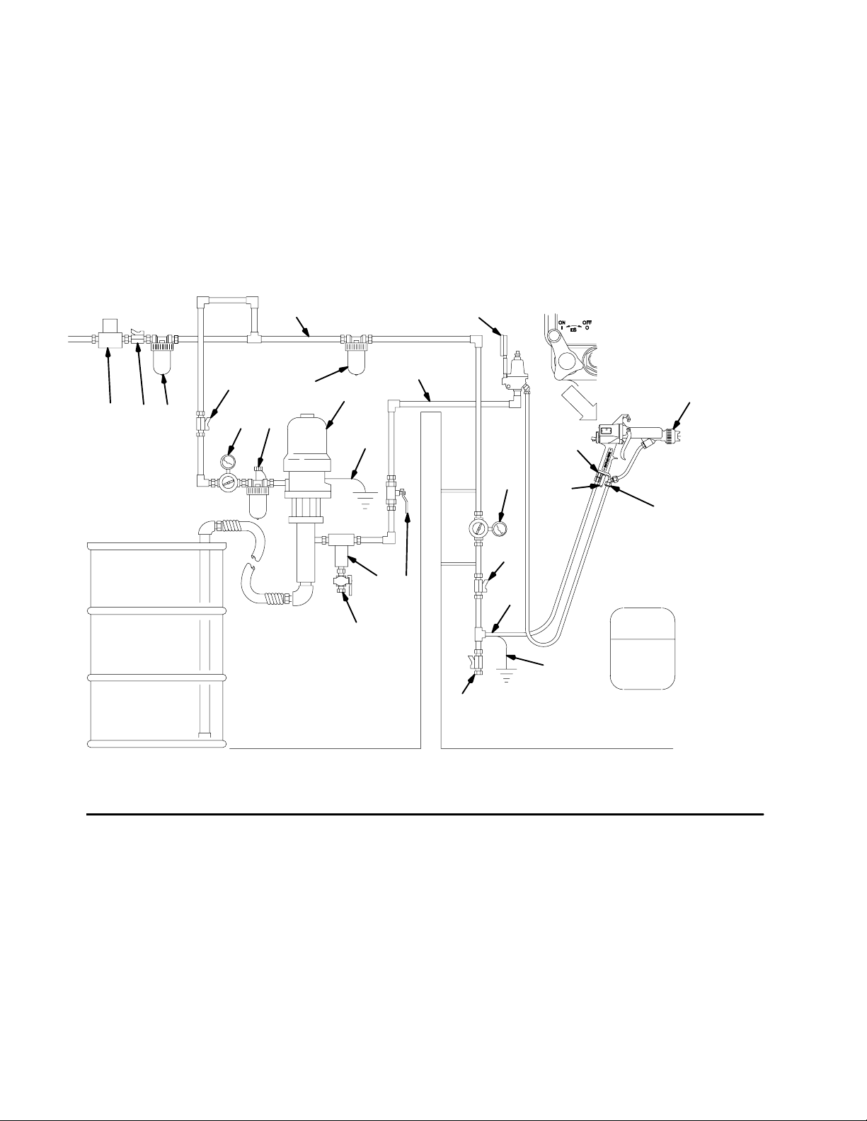
KEY
A Main Air Supply Line
B* Ventilation Fan Interlock Solenoid Valve
C* Main Air Supply Shutoff Valve (bleed-type)
D Air & Water Separator
E* Pump Air Supply Shutoff V alve (bleed-type)
F Air Line Lubricator
G Air Pressure Regulator
H Pump
J* Pump Ground Wire
K Fluid Filter
L Fluid Supply Line Shutoff Valve
M Fluid Pressure Regulator
N Fluid Supply Line
O Air Filter (20 micron)
Installation
P Air Supply Line Shutoff Valve
Q* Air Hose Ground Wire
R* Graco Electrically Conductive Air Hose
S Electrostatic Spray Gun
T Air Line Drain Valve
U* Fluid Drain Valve
V Gun Air Inlet
W Gun Fluid Inlet
X Gun Exhaust Tube
* Required for safe operation. Must purchase separately. See
Accessories. NOTE: Solenoid Valve (B) is not offered as a Graco
accessory.
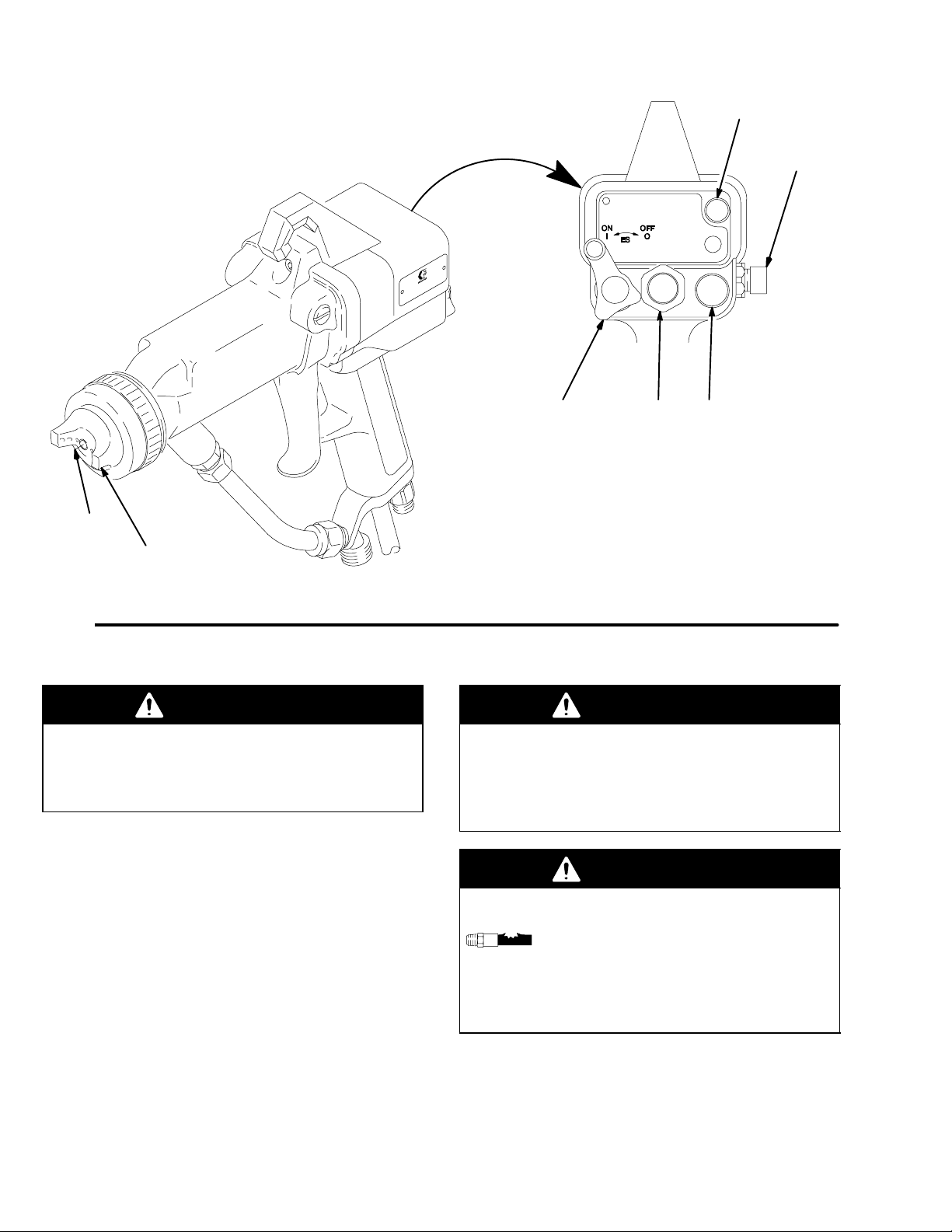
AM
ES ON-OFF Lever
1 is ON 0 is OFF
Fig. 1
N
B* C* D
E*
GF
O
H
J*
K L
U*
Non-hazardous Area Hazardous Area
The air supply to the gun must be electrically interlocked with the ventilators
to prevent the power supply from operating without ventilating fans on.
S
V
G
X
W
P
R
WARNING
SIGN
Q*
T
0389
6 307912
Page 7
Installation
Connect the Air Line (Refer to Fig. 1)
WARNING
ELECTRIC SHOCK HAZARD
To reduce the risk of an electric shock or
other serious injury, the air supply hose
must be electrically connected to a true
earth ground. Use Only Graco Electrically Con-
ductive Air Supply Hose.
1. Connect the Graco Electrically Conductive Air
Supply Hose (R) between the air supply line and
the gun’s air inlet (V). The gun air inlet fitting has a
left hand thread. Connect the air supply hose
ground wire to a true earth ground.
2. Install an air line filter (O) and an air and water
separator (D) on the air line to ensure a dry, clean
air supply to the gun. Dirt and moisture can ruin
the appearance of your finished workpiece and can
cause the gun to malfunction.
3. Install a bleed-type air regulator (G) on the pump
and gun air supply lines to control air pressure to
the pump and gun.
4. Install a bleed-type air shutoff valve on the main air
line (C) and the pump air line (E) to shut off air to
the pump. Install an additional bleed-type valve on
each pump air supply line to relieve air trapped
between this valve and the pump after the air
regulator is shut off.
5. Install an air line lubricator (F) as close to the
pump (H) as possible.
6. Install an air shutoff valve (P) on each gun air
supply line to shut off air to the gun(s).
Connect the Exhaust Tube
Press the exhaust tube (provided) onto the barbed
adapter on the bottom of the gun handle. Secure the
tube with the clamp provided. Refer to page 34.
Connect the Fluid Line (Refer to Fig. 1)
1. Before connecting the fluid line (N), blow it out with
air and flush it with solvent. Use solvent which is
compatible with the fluid to be sprayed.
2. Install a fluid regulator (M) on the fluid line to
control fluid pressure to the gun.
3. Install a fluid filter (K) and drain valve (U) at the
pump outlet.
WARNING
PRESSURIZED EQUIPMENT HAZARD
The fluid drain valve (U) is required in your system
to assist in relieving fluid pressure in the displacement pump, hose and gun; triggering the gun to
relieve pressure may not be sufficient. Install a
drain valve close to the pump’s fluid outlet. The
drain valve reduces the risk of serious injury,
including splashing in the eyes or on the skin.
WARNING
PRESSURIZED EQUIPMENT HAZARD
The bleed-type air shutoff valve is required in your
system to relieve air trapped between this valve
and the pump after the air regulator is closed.
Trapped air can cause the pump to cycle unexpectedly, which could result in serious injury, including
splashing in the eyes or on the skin.
4. Connect the fluid line to the 3/8–18.6(m) gun fluid
inlet (W).
5. Before running any paint through the spray gun,
flush it out with a compatible solvent.
307912 7
Page 8
Installation
Ground the System
WARNING
FIRE, EXPLOSION, AND
ELECTRIC SHOCK HAZARD
When operating the electrostatic device,
any ungrounded objects in the spray
area (such as people, containers, tools,
etc.) can become electrically charged.
Improper grounding can result in static
sparking, which can cause a fire, explosion, or electric shock. Follow the
grounding instructions below.
The following are minimum grounding requirements for
a basic electrostatic system. Your system may include
other equipment or objects which must be grounded.
Check your local electrical code for detailed grounding
instructions. Your system must be connected to a true
earth ground.
1. Pump: ground the pump by connecting a ground
wire and clamp as described in your separate
pump instruction manual.
2. Air compressors and hydraulic power supplies:
ground the equipment according to the manufacturer’s recommendations.
3. Electrostatic Air Spray Gun: ground the gun by
connecting the Graco Electrically Conductive Air
Hose and connecting the air hose ground wire to a
true earth ground. Check the electrical grounding
of the gun as instructed on page 9.
4. All air and fluid lines must be properly grounded.
Use only grounded hoses with a maximum of 500
feet (150 m) combined hose length to ensure
grounding continuity.
5. All electric cables must be properly grounded.
6. All persons entering the spray area: their shoes
must have conductive soles, such as leather, or
personal grounding straps must be worn. Rubber
or plastic soles are not conductive. The operator
must not wear gloves that insulate the hand from
the spray gun. The gloves must be conductive or
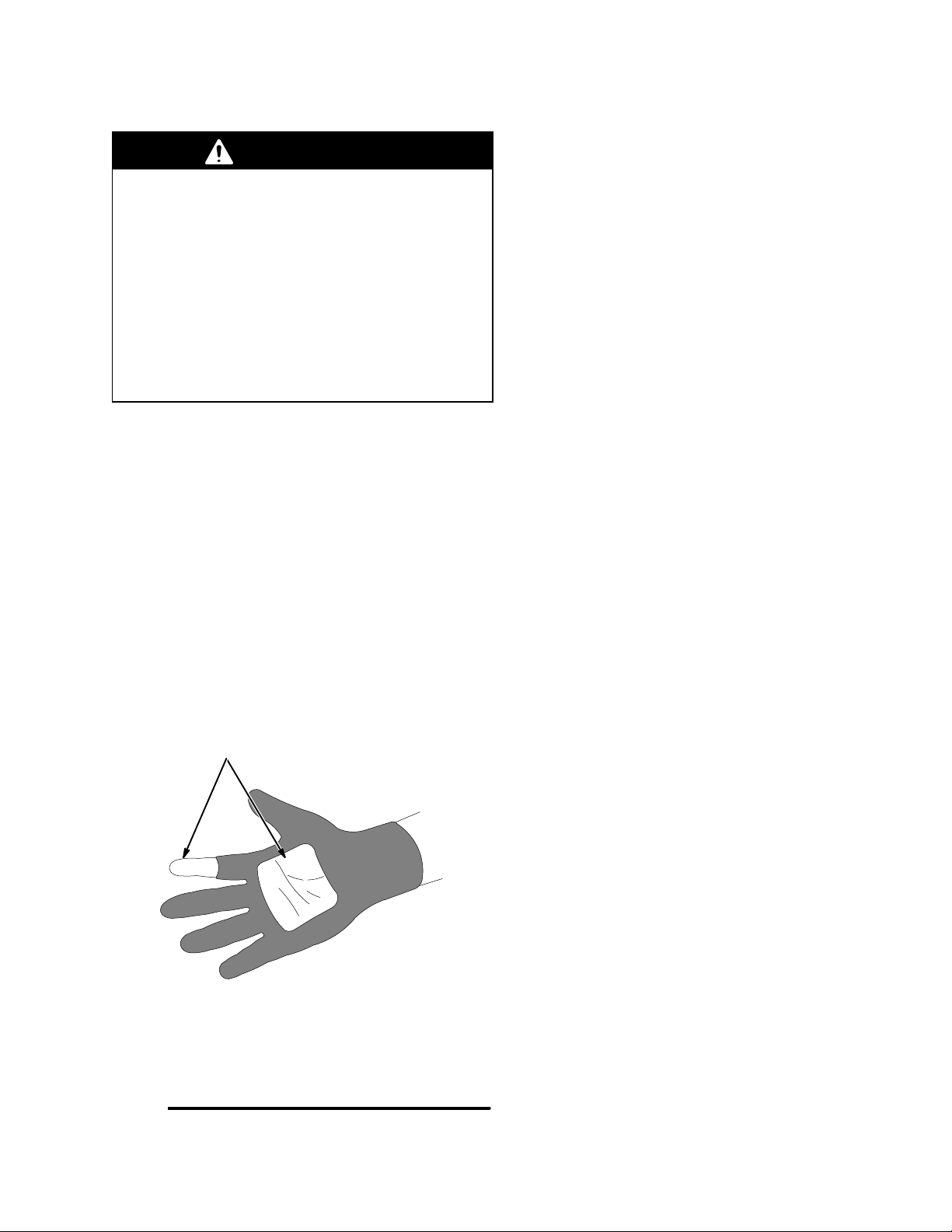
modified as shown in Fig. 3, page 11.
7. Object being sprayed: keep the workpiece hangers
clean and grounded at all times. Contact points
must be sharp points or like knife edges.
8. The floor of the spray area: must be electrically
conductive and grounded. Do not cover the floor
with cardboard or any non-conductive material
which would interrupt grounding continuity.
9. Flammable liquids in the spray area: must be kept
in approved, grounded containers. Do not store
more than the quantity needed for one shift.
10. All electrically conductive objects or devices in the
spray area: including fluid containers and wash
cans, must be properly grounded.
8 307912
Page 9
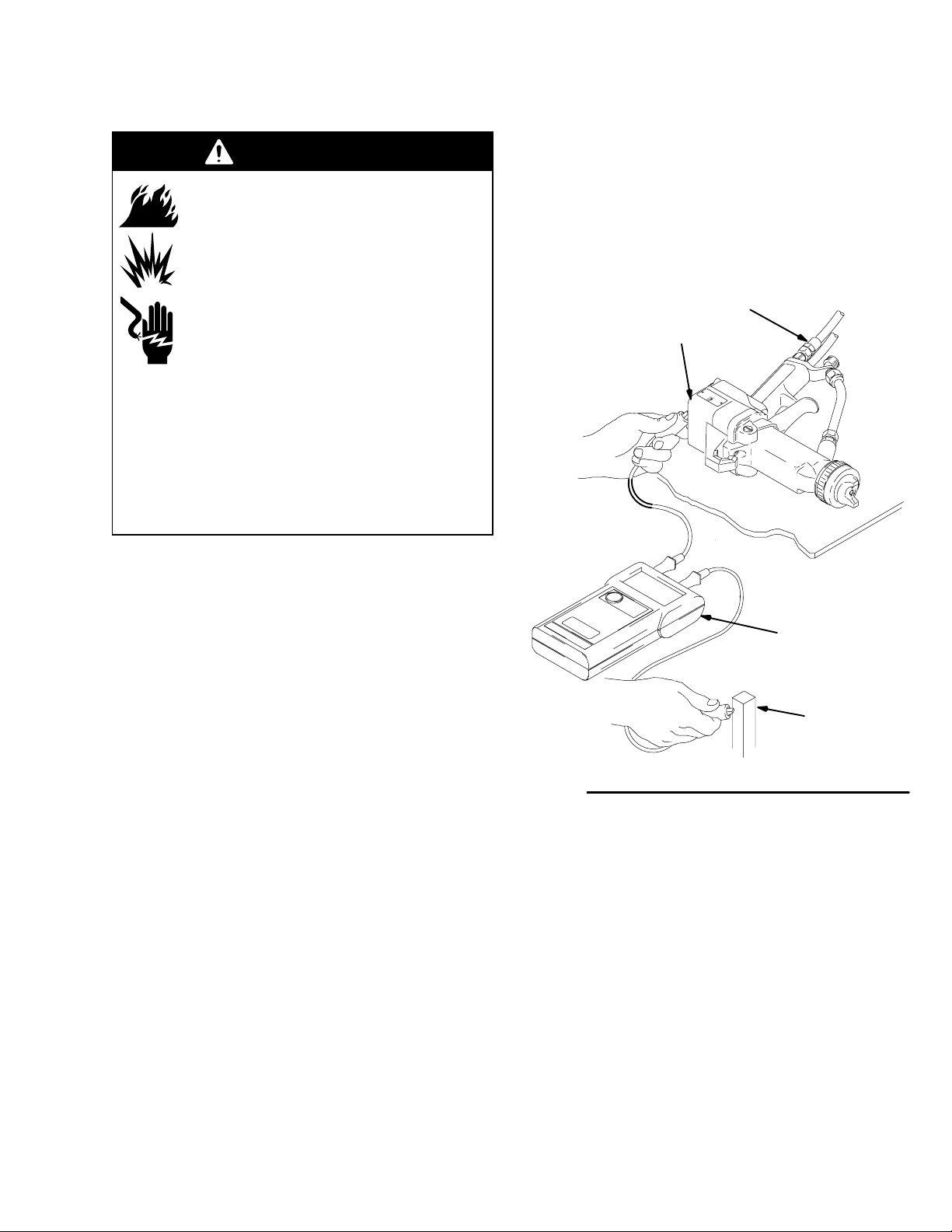
Installation
Check the Electrical Grounding (See Fig. 2)
WARNING
FIRE, EXPLOSION, AND
ELECTRIC SHOCK HAZARD
Megohmmeter P/N 241079 (AA-see Fig.
2) is not approved for use in a hazardous area. To reduce the risk of sparking,
do not use the megohmmeter to check
electrical grounding unless:
The gun has been removed from the
hazardous area;
Or all spraying devices in the hazardous area
are turned off, ventilation fans in the hazardous
area are operating, and there are no flammable
vapors in the area (such as open solvent containers or fumes from spraying).
Failure to follow this warning could cause fire,
explosion, electric shock and result in serious injury
and property damage.
b. If using a red turbine air hose, use an ohmme-
ter to measure the resistance. Resistance
should not exceed 100 ohms.
6. If the resistance is greater than the maximum
reading specified above for your hose, check the
tightness of the ground connections and be sure
the air hose ground wire is connected to a true
earth ground. If the resistance is still too high,
replace the air hose.
R
BB
1. Have a qualified electrician check the electrical
grounding continuity of the spray gun and air hose.
2. Turn the ES ON-OFF Lever to OFF. See Fig. 4,
page 12, for the location of the lever.
3. Turn off the air and fluid supply to the gun. The
fluid hose must not have any fluid in it.
4. Make sure the air hose (R) is connected and the
hose ground wire is connected to a true earth
ground.
5. Measure the resistance between the gun handle
(BB) and a true earth ground (CC).
a. If using a black or grey air hose, use a me-
gohmmeter (AA) to measure the resistance.
Use an applied voltage of 500 minimum to
1000 volts maximum. The resistance should
not exceed 2 megohms.
AA
CC
0644B
Fig. 2
307912 9
Page 10

Notes
10 307912
Page 11
Operation
Pressure Relief Procedure
WARNING
PRESSURIZED EQUIPMENT HAZARD
The system pressure must be manually relieved to
prevent the system from starting or spraying accidentally. To reduce the risk of an injury from electric
shock, accidental spray from the gun, splashing
fluid, or moving parts, follow the Pressure Relief
Procedure whenever you:
are instructed to relieve the pressure,
stop spraying,
check or service any of the system equipment,
or install or clean the fluid nozzle.
1. Turn the ES ON–OFF Lever to OFF.
2. Turn off the air and fluid supply to the gun.
3. Trigger the gun into a grounded metal waste
container to relieve fluid pressure.
4. Open the pump drain valve, having a waste container ready to catch the drainage.
5. Leave the pump drain valve open until you are
ready to spray again.
Filter the Fluid
Operating Checklist
Check the following list daily, before starting to operate
the system, to help ensure safe, efficient operation.
____ 1. All the operators are properly trained to
safely operate an electrostatic air spray
system as instructed in this manual.
____ 2. All the operators are trained how to properly
relieve pressure as instructed at left.
____ 3. The system is thoroughly grounded and the
operator and all persons entering the spray
area are properly grounded. See Ground
the System, page 8.
____ 4. The operator is not wearing gloves which
insulate the hand from the spray gun. If
worn, gloves must be conductive or modified
as shown in Fig. 3 so as not to interfere with
the operator grounding through the gun.
____ 5. The condition of the electrical components of
the spray gun has been checked as
instructed in Electrical Tests, page 19.
____ 6. The ventilation fans are operating properly.
____ 7. The workpiece hangers are clean and
grounded. Contact points must be sharp
points or like knife edges.
Filter the fluid to remove coarse particles and sediment
which could clog the spray nozzle.
3 in. (76 mm) square cut out and finger of glove cut off
NOTE: If gloves are worn, they must be conductive or
modified as shown so they do not interfere with operator
grounding through the gun.
Fig. 3
06445
____ 8. All the debris, including flammable liquids
and rags, is removed from the spray area.
____ 9. All flammable liquids in the spray booth are
in approved, grounded containers.
____ 10. All conductive objects in the spray area are
electrically grounded and the floor of the
spray area is electrically conductive and
grounded.
307912 11
Page 12
Operation
DD
31
20
1
06443
Fig. 4
Selecting a Fluid Nozzle and Air Cap
WARNING
PRESSURIZED EQUIPMENT HAZARD
To reduce the risk of an injury, follow the Pressure
Relief Procedure on page 11 before removing or
installing a fluid nozzle and/or air cap.
The gun is supplied with a 0.059 in. (1.5 mm) fluid
nozzle, P/N 185158, and air cap, P/N 193033. If your
application requires a different nozzle and air cap
combination, use instruction manual 307803 or consult
your authorized Graco distributor to select the appropriate fluid nozzle and air cap. Install the air cap
and fluid nozzle into the gun barrel as instructed in Air
Cap/Nozzle/Resistor Stud Replacement, page 22.
26 43
45
05151A
Operating the Spray Gun
WARNING
PRESSURIZED EQUIPMENT HAZARD
To reduce the risk of an injury, follow the Pressure
Relief Procedure on page 11 whenever you stop
spraying and whenever you are instructed to
relieve pressure.
WARNING
COMPONENT RUPTURE HAZARD
To reduce the risk of component rupture,
which can cause serious injury, do not
exceed the maximum working pressure
of the lowest rated system component. This equipment has a 100 psi (7 bar, 0.7 MPa) maximum
working air and fluid pressure.
12 307912
Follow the steps on page 13 to establish the correct
fluid flow and air flow. Do not turn the ES ON-OFF
lever to ON yet.
Page 13

Operation
Operating the Spray Gun (continued)
1. Follow the Operating Checklist on page 11.
2. To adjust the air cap for a vertical or horizontal
spray pattern, first make sure the pressure is
relieved. Then loosen the air cap retaining nut, and
rotate the air cap as directed in Fig. 5. Tighten the
retaining nut until the air cap is held firmly in place;
you should not be able to rotate the air cap horns
by hand.
Vertical Pattern
Horizontal Pattern
Fig. 5
3. Adjust the fluid flow by using the fluid line pressure
regulator. Refer to instruction manual 307803 to
set the fluid pressure for various fluid flows, according to the size of the fluid nozzle being used.
4. If necessary, further adjust the fluid flow rate with
the fluid adjustment knob (45). See Fig. 4.
5. Fully open the fan air valve (43).
02020
7. Set the atomizing air valve (31) about 1.5 turns out
for most applications. The Atomizing Air Valve
Adjustment chart shows the effect of the atomizing air valve adjustment on the air cap air flow.
8. Adjust the pattern width with the fan air valve (43).
Atomizing Air Valve Adjustment
100
90
80
70
60
50
40
30
20
Air Cap Air Flow (%)
10
0
0.00 0.50 1.00 1.50 2.00 2.50 3.00
Fully Open Fully Closed
Valve Turns
Fine Adjustments of the Spray Gun
To improve the atomization, open the atomizing air
valve further (31). If more atomizing air is needed
beyond the fully open position of the valve, increase
the air hose inlet pressure.
Use the lowest air flow settings needed for acceptable atomization. The slower particle velocity will
improve the electrostatic effect.
To reduce the atomization air and minimize any
overspray, turn the atomizing air valve in.
6. Set the air pressure with the air pressure regulator.
The following chart shows the air hose inlet pressure required to get full voltage from the power
supply. To avoid shortening the turbine life, do not
exceed the recommended air pressures.
Air Hose
Length
ft. (m)
15 (4.6) 45 to 50 (3.1 to 3.5, 0.31 to 0.35)
25 (7.6) 50 to 55 (3.5 to 3.8, 0.35 to 0.38)
50 (15.3) 60 to 65 (4.2 to 4.5, 0.42 to 0.45)
75 (22.9) 68 to 73 (4.7 to 5.0, 0.47 to 0.50)
100 (30.5) 75 to 80 (5.2 to 5.5, 0.52 to 0.55)
Dynamic pressure at air hose inlet
required for full voltage
psi (bar, MPa)
NOTE: See the Spray Pattern Troubleshooting
chart on page 16 to correct spray pattern problems.
9. Turn the ES ON-OFF lever to ON to begin spraying with the electrostatics. When spraying, the ES
indicator light (DD) should glow, indicating the
electrostatic charge.
CAUTION
Hang the gun with its nozzle pointing down when it is
not being used to avoid having fluid run into the gun
air passages. Fluid in the gun air passages can
cause poor atomization and excessive current demands and damage the gun.
307912 13
Page 14
Operation
Shutdown
WARNING
PRESSURIZED EQUIPMENT HAZARD
To reduce the risk of an injury, follow the Pressure
Relief Procedure on page 11 whenever you stop
spraying and whenever you are instructed to
relieve pressure.
Maintenance
Daily Care and Cleaning
WARNING
PRESSURIZED EQUIPMENT HAZARD
To reduce the risk of an injury, follow the Pressure
Relief Procedure on page 11 when you stop
spraying, before cleaning or flushing the spray gun,
and whenever you are instructed to relieve the
pressure.
WARNING
FIRE, EXPLOSION, AND ELECTRIC
SHOCK HAZARD
To reduce the risk of fire, explosion, or
electric shock, turn the ES ON-OFF
lever OFF before flushing the gun.
1. Relieve the pressure.
2. Flush and clean the equipment. Follow the instruction in Maintenance.
1. Clean the fluid and air line filters daily.
2. Clean the outside of the gun daily with a soft cloth
dampened in a compatible solvent.
3. Clean the air cap and fluid nozzle daily, minimum.
See page 15. Some applications require more
frequent cleaning. Replace the fluid nozzle and air
cap if they are damaged. See page 22.
4. Check the electrode wire. Straighten it if it is bent,
and replace it if it is broken or damaged. See page
23.
5. Check for fluid leakage from the gun and fluid
hoses. Tighten fittings or replace equipment as
needed.
6. Check all of the work hangers for build-up of
material; clean them if necessary.
CAUTION
Fluid left in gun air passages could result in a poor
quality paint finish and may draw current and reduce
the electrostatic effect. Fluid in the power supply
cavity can reduce the alternator life.
Immersing the gun in fluid is not recom-
mended.
Do not use any cleaning method which may
allow solvent into the gun air passages.
Point the gun down while cleaning to prevent
fluid from running into the air passages. See
Fig. 6.
Hang the gun with its nozzle pointing down
when it is not being used.
Clean all parts with a non-conductive, compatible
solvent. Conductive solvents can cause the gun to
malfunction.
Methylene chloride is not recommended as a flushing or cleaning solvent with this gun as it will damage
nylon components.
7. Flush the gun before changing colors and whenever you are done operating the gun. See page 15.
14 307912
Page 15

Maintenance
Clean the Air Cap and Fluid Nozzle
WARNING
CAUTION
Do not use metal tools to clean the air cap or spray
nozzle holes as this could scratch them, and make
sure the electrode wire is not damaged. Scratches in
the air cap or spray nozzle or a damaged electrode
wire can distort the spray pattern.
Equipment needed:
Soft bristle brush
Compatible solvent
Procedure:
WARNING
PRESSURIZED EQUIPMENT HAZARD
To reduce the risk of an injury, follow the Pressure
Relief Procedure on page 11 whenever you stop
spraying, before installing or cleaning the fluid
nozzle, and whenever you are instructed to relieve
the pressure.
1. Relieve the pressure.
2. Remove the air cap assembly.
PRESSURIZED EQUIPMENT HAZARD
To reduce the risk of an injury, follow the Pressure
Relief Procedure on page 11 whenever you stop
spraying and whenever you are instructed to
relieve the pressure.
1. Relieve the pressure.
2. Disconnect and plug the fluid line.
3. Connect the solvent supply to the gun.
4. Flush the gun with compatible solvent into a
grounded container until it is clean.
5. Relieve the pressure.
6. Disconnect and plug the solvent line.
7. Trigger the gun into a grounded container to drain
out the solvent remaining in the gun.
8. Place the gun in its hanging bracket, with the
nozzle pointing down, until it is used again.
9. When ready to spray again, reconnect the fluid
supply line.
3. With the front of the gun pointed down, clean the
air cap, fluid nozzle, and front of the gun, using a
soft bristle brush and compatible solvent. See Fig.
6.
4. Carefully re-install the air cap assembly. Avoid
bending the electrode. Tighten the retaining nut
until it is snug, allowing the air cap to turn with
resistance.
5. Test the gun resistance as instructed on page 19.
Flush the Spray Gun
WARNING
ELECTRIC SHOCK HAZARD
To reduce the risk of fire, explosion, or
electric shock, turn the ES ON-OFF
lever OFF before flushing the gun.
10. Turn on the fluid and air supplies.
11. Make sure the ES ON-OFF lever is OFF.
12. Trigger the gun until it is clear of solvent.
06446
Fig. 6
307912 15
Page 16

Troubleshooting
WARNING
ELECTRIC SHOCK HAZARD
Installing and servicing this equipment
requires access to parts which may
cause an electric shock or other serious
injury if the work is not performed properly. Do not
PRESSURIZED EQUIPMENT HAZARD
To reduce the risk of an injury, follow the Pressure
Relief Procedure on page 11 before checking or
servicing any part of the system and whenever you
are instructed to relieve the pressure.
WARNING
install or service this equipment unless you are
trained and qualified.
NOTE: Check all possible remedies in the Troubleshooting Chart before disassembling the gun.
Spray Pattern Troubleshooting
NOTE: Some spray pattern problems are caused by the improper balance between air and fluid.
Problem Cause Solution
Fluttering or spitting spray
Improper spray pattern
The fluid supply is insufficient. Adjust the fluid regulator, or fill the fluid
supply.
The fluid nozzle is loose, or the fluid nozzle taper seat is damaged.
There is dirt between the fluid nozzle,
taper seat, and gun body.
The coupler at the fluid inlet is loose or
cracked.
Loose fluid tube in tank. Tighten.
There is fluid build-up on the air cap;
partially clogged horn holes; or full air
pressure from the clean horn hole forces
the fan pattern toward the clogged end.
The electrode is bent. Straighten the electrode.
The fluid nozzle or air cap holes are dam-
aged.
There is fluid buildup on the perimeter of
the fluid nozzle orifice, or a partially
clogged fluid nozzle orifice.
The electrode is bent. Straighten the electrode wire.
The fan air pressure is too high. Reduce the fan air pressure.
Tighten or replace the fluid nozzle; see
page 22.
Clean the parts; see page 15.
Tighten or repair the coupler .
Clean the air cap with a soft implement or
submerge it in water and wipe it clean;
see page 15.
Replace the damaged part; see page 22.
Remove the obstruction; never use wire
or hard instruments; see page 15.
Streaks
16 307912
The fluid is too thin. Increase the fluid viscosity.
There is not enough fluid pressure. Increase the fluid pressure.
The fan air pressure is too low. Increase the fan air pressure.
The fluid is too thick. Reduce the fluid viscosity.
There is too much fluid. Reduce the fluid flow. Reduce fluid pres-
sure on pressure feed guns and/or adjust
the fluid adjusting screw until proper pattern is obtained.
The last coat of fluid is applied too wet. Apply a drier finish using multiple strokes.
There is too much air pressure. Decrease the air pressure.
The air pressure is insufficient. Increase the air pressure.
The spray pattern is non-uniform. Clean or replace the air cap; see page 15
or 22.
Page 17

Troubleshooting
Gun Operation Troubleshooting
Problem Cause Solution
Fluid leakage from the fluid packing
area
Air leakage from the front of the gun
Fluid leakage from the front of the gun
“Orange Peel” finish
Excessive spray fog
No fluid sprays from the gun The fluid supply is low. Check the fluid supply; add fluid if
The equipment is covered with fluid
The air cap is dirty
The needle packings or shaft are worn. Replace the packings or shaft; see page
26.
The packing nut is loose Tighten the packing nut; see page 26.
The air valve is not seating properly. Clean and service the air valve; see page
31.
The air valve o-ring is sticking. Lubricate the o-ring; see page 31.
The needle is worn or damaged. Replace the needle; see page 26.
The fluid seat is worn. Replace the fluid nozzle and/or electrode
needle; see pages 26 to 23.
The fluid packing is too tight. Lubricate and adjust the packing nut; see
page 26.
The resistor stud is loose. Tighten the resistor stud; see page 22.
The fluid nozzle is loose. Tighten the fluid nozzle; see page 22.
The resistor stud o-ring is damaged. Replace the o-ring; see page 22.
The air pressure is insufficient for good
atomization.
The fluid is poorly mixed or filtered. Remix or refilter the fluid.
An improper thinner is being used. Use the proper thinner.
The air pressure is too high. Reduce the air cap air pressure by closing
The fluid is thinned too much. Properly thin the fluid.
The air cap is damaged. Replace the air cap; see page 22.
The fluid nozzle is dirty or clogged. Clean the fluid nozzle; see page 15.
The fluid nozzle is damaged. Replace the fluid nozzle; see page 22.
The fluid adjustment valve is damaged. Replace the o-ring; see page 31.
The exhaust air flow is insufficient or not
directed properly.
The distance between the gun and work-
piece is incorrect.
The air cap and fluid nozzle are mis-
aligned.
Increase the air cap air pressure by open-
ing the atomizing air valve more or in-
creasing the gun air inlet pressure; use
the least air pressure needed for good
results.
the atomizing air valve more or decreas-
ing the gun air inlet pressure; use the
least air pressure needed for good results.
Do not reduce below minimum pressure
needed for full voltage. See page 13.
necessary.
Check for the proper CFM; check the
baffles and direction of the air flow.
Adjust the spraying distance to 8 to 12
inches (203 to 305 mm).
Check the air cap and fluid nozzle seat for
fluid buildup.
Air Cap
Fluid Nozzle
ALIGNED MISALIGNED
Clean or replace parts as needed; see
page 15 or 22.
307912 17
Page 18

Troubleshooting
Electrical Troubleshooting
Problem Cause Solution
Poor wrap-around The ES ON-OFF lever is in the OFF (O)
position.*
The distance between the gun and work-
piece is incorrect.
The parts are poorly grounded. Clean the workpiece hangers. Check for
The booth exhaust velocity is too high. Reduce exhaust velocity within code limits.
The atomizing air pressure is too high. Reduce the atomizing air pressure.
The fluid pressure is too high. Reduce the fluid pressure.
The fluid viscosity is not right for electros-
tatic spray.
The fluid resistivity is too low. Check the fluid resistivity with a paint meter
The turbine alternator is not operating.* Check if the ES ON-OFF lever is ON (1).
The gun resistance is faulty. Check the gun resistance. See page 19.
Fluid leaks from the needle packing and
causes a short.
The turbine alternator is faulty. Be sure the plug is in place on the back of the
Operator gets a mild shock The operator is not properly grounded or
is near an ungrounded object.
The gun is not properly grounded. See Check the Electrical Grounding,
Operator gets a shock when
touching the workpiece
The workpiece is not properly grounded. Clean workpiece hangers. Check for proper
Turn the lever to ON (1).
Adjust the spraying distance to 8 to 12 inches
(203 to 305 mm)
proper grounding on the conveyer or track.
Check with the supplier for proper fluid viscosity for electrostatic spray.
and probe.
Check the air supply to the gun. Check for dirt
or moisture in the turbine. See page 28.
Clean the needle cavity. Replace the fluid
needle. See page 26.
turbine alternator housing. Remove and test
the turbine alternator. See page 28.
Be sure the floor and the operator are properly
grounded. See Ground the System, page 8.
page 9.
grounding on the conveyor or track.
* ES indicator light is not on when the gun is triggered.
18 307912
Page 19

Electrical Tests
The performance and safety of the spray gun are
directly affected by the condition of the electrical
components contained inside the gun. The electrical
tests below can be used to determine the condition of
the power supply (18) and the resistor stud (22) as well
as the continuity of the electrical path between the
components.
Use megohmmeter P/N 241079 (A) and an applied
voltage of 500 volts to complete these electrical tests.
Connect the leads as shown.
WARNING
FIRE, EXPLOSION, AND
ELECTRIC SHOCK HAZARD
Megohmmeter P/N 241079 (A-see Fig.
7) is not approved for use in a hazardous area. To reduce the risk of sparking,
do not use the megohmmeter to do
electrical tests unless:
The gun has been removed from the
hazardous area;
Measure the resistance between the end of the electrode (20) and the gun air fitting (17). See Fig. 7. The
resistance should be between 180 to 220 megohms. If
the resistance is outside the specified range, go to the
next test. If the resistance is correct, resume spraying
or refer to the Electrical Troubleshooting chart on
page 18 for other possible causes of poor performance.
A
Or all spraying devices in the hazardous area
are turned off, ventilation fans in the hazardous
area are operating, and there are no flammable
vapors in the area (such as open solvent containers or fumes from spraying).
Failure to follow this warning could cause fire,
explosion, electric shock and result in serious injury
and property damage.
Test Gun Resistance
Check the resistance with the gun triggered and with
the trigger released. The fluid passage must be
flushed and dried to get an accurate reading.
Fig. 7
20
17
06447B
Continued on the next page.
307912 19
Page 20

Electrical Tests
Test Power Supply Resistance
Remove the power cartridge (18) from the gun handle.
See Power Cartridge Replacement on page 27.
Remove the turbine alternator from the power cartridge. See Turbine Alternator Removal on page 28.
Measure the resistance from the power supply’s
ground contact point (EE) to the contact spring (18c)
on the other end of the power supply. See Fig. 8.
The resistance should be 157.5 to 192.5 megohms. If
the resistance is outside the specified range, the
power supply is defective and must be replaced. If the
resistance of the power supply is correct, proceed to
the next test.
If you still have problems, refer to the Electrical
Troubleshooting chart on page 18 for other possible
causes of poor performance, or contact the nearest
authorized service agency.
Test Resistor Stud Resistance
Insert a conductive rod (B) into the gun barrel (removed for the power supply test) and against the metal
contact (C) in the front of the barrel. See Fig. 9.
Fig. 8
18c
18
A
EE
03566B
A
Measure the resistance between the conductive rod
(B) and the gun electrode (20). The resistance should
be 21 to 29 megohms. If the resistance is correct,
resume spraying or refer to the Electrical
Troubleshooting chart on page 18 for other possible
causes of poor performance. Contact the nearest
authorized service agency if problems continue.
20
Fig. 9
C
Continued on the next page.
B
06448B
20 307912
Page 21

Electrical Tests
Test Resistor Stud Resistance (continued)
If the resistance is outside the specified range, remove
the resistor stud (22). See Air Cap/Nozzle/Resistor
Stud Replacement on page 22. Check the resistance
between the black resistor stud contact ring (D) and
the needle contact ring (E). Refer to Fig. 10. You may
have to press down on the contact ring (D) in several
places to get a good reading.
The resistance should be 21 to 29 megohms. If the
resistance is correct, make sure the metal contact (C)
in the barrel and the needle contact wire (E) are clean.
If the resistance is outside the specified range, the
resistor is defective and the resistor stud (22) must be
replaced. See Air Cap/Nozzle/Resistor Stud Re-
placement on page 22.
WARNING
FIRE, EXPLOSION, AND
ELECTRIC SHOCK HAZARD
The resistor stud contact ring (D) is a
conductive contact ring, not a sealing
o-ring. See Fig. 10. To reduce the risk of
sparking or electric shock, do not
remove the resistor stud contact ring (D)
or operate the gun without the contact
ring in place. Do not replace the resistor
stud (22) with anything but a genuine
Graco part.
Fig. 10
D
E
0442
307912 21
Page 22

Service
Prepare the Gun for Service
WARNING
ELECTRIC SHOCK HAZARD
Installing and servicing this equipment
requires access to parts which may
cause an electric shock or other serious
injury if the work is not performed properly. Do not
install or service this equipment unless you are
trained and qualified.
WARNING
PRESSURIZED EQUIPMENT HAZARD
To reduce the risk of injury, follow the Pressure
Relief Procedure on page 11 before checking or
servicing any part of the system and whenever you
are instructed to relieve the pressure.
NOTE:
Check all possible remedies in Troubleshooting
before disassembling the gun.
Air Cap/Nozzle/Resistor Stud
Replacement
CAUTION
Hold the front end of the gun up, and trigger the gun
while removing the nozzle and resistor stud to help
drain the gun and prevent any fluid left in the gun
from entering the air passages.
1. Prepare the gun for service as instructed at left.
2. Remove the air cap assembly. Point the front end
of the gun up and squeeze the trigger while removing the fluid nozzle/resistor stud (21, 22) assembly
with the multi-tool (62). See Fig. 11, page 23.
NOTE: If the resistor stud remains in the gun when the
fluid nozzle is removed, start the nozzle thread onto
the stud and pull the stud out.
3. Unscrew and remove the resistor stud (22) with
the multi-tool (62). See Fig. 12.
If the plastic parts of the gun must be held securely,
always clamp them in padded vice jaws to prevent
damage to the parts.
Lightly lubricate o-rings and seals with petroleum
jelly. Do not over-lubricate.
Only use genuine Graco parts. Do not mix or use
parts from other PRO Gun models. See page 35.
1. Flush the gun as instructed in Flush the Spray
Gun, page 15.
2. Relieve the pressure.
3. Disconnect the air and fluid lines from the gun.
4. Remove the spray gun from the worksite for
service or repair. Service or repair area must be
clean.
WARNING
FIRE, EXPLOSION, AND
ELECTRIC SHOCK HAZARD
The resistor stud contact ring (D) is a
conductive contact ring, not a sealing
o-ring. See Fig. 11. To reduce the risk of
sparking or electric shock, do not
remove the resistor stud contact ring (D)
except to replace it and never operate
the gun without the contact ring in place.
Do not replace the contact ring with
anything but a genuine Graco part.
To install the resistor stud:
4. Lightly lubricate the o-ring (25) with petroleum jelly
and install it on the resistor stud (22).
5. Using the multi-tool (62), install the resistor stud
(22) in the fluid nozzle (21). Tighten to 10 in-lb
(1.12 Nm).
NOTE: Make sure the electrode (20) is tightened
properly, as shown in Fig. 13.
22 307912
Continued on the next page.
Page 23

Service
Air Cap/Nozzle/Resistor Stud
Replacement (continued)
6. Trigger the gun while installing the fluid nozzle (21)
and resistor stud (22) assembly with the multi-tool
(62). Tighten until the fluid nozzle seats in the gun
barrel.
7. Install the air cap assembly (1, 2, 8). Test the gun
resistance as instructed on page 19.
1, 8
2
62
21
22
20
D
25
3. Unscrew and remove the fluid needle/electrode
(20) with the multi-tool (62). See Fig. 13. Hold the
needle shaft end to prevent it from turning.
CAUTION
Be careful not to damage the contact wire when
removing the electrode from the gun.
4. Apply low-strength (purple) Loctite or equivalent
thread sealant to the electrode and needle shaft
threads. Install the new electrode finger-tight. Do
not over-tighten it.
CAUTION
To avoid damaging the plastic threads or contact
wire, be very careful when installing the electrode.
5. Install the fluid nozzle, resistor stud, and air cap
assembly as instructed at left.
6. Test the gun resistance as instructed on page 19.
Apply a very light coat of lubricant
Tighten 1/8 to 1/4 turn past hand tight
Fig. 11
21
22
62
Torque to 10 in-lbs (1.12 Nm)
Fig. 12
06449
0444A
Electrode Replacement
1. Prepare the gun for service as instructed on page
22.
2. Remove the air cap, nozzle and resistor stud as
instructed on page 22.
20
Apply low-strength (purple) Loctite or equivalent to needle shaft
threads
Fig. 13
62
06450
307912 23
Page 24

Service
Barrel Removal
1. Prepare the gun for service as instructed on page
22.
2. Carefully loosen the nut from the fluid fitting (10).
Pull the tube (12) out of the fitting. Make sure both
ferrules and the nut stay with the tube. See Fig.
14.
3. Using the wrench (63) supplied, loosen the three
socket head cap screws (5).
4. Hold the gun handle (7) with one hand and pull the
barrel (3) straight away from the handle to remove
it. See Fig. 15.
CAUTION
To avoid damaging the power cartridge (18), pull the
gun barrel straight away from the gun handle. If
necessary, gently move the barrel from side to side
to free it from the gun handle.
3
7
18
06452
Fig. 15
Fig. 14
12
10
63
5
06451
24 307912
Page 25

Service
Fluid Packing Removal
1. Prepare the gun for service as instructed on page
22.
2. Remove the air cap assembly, fluid nozzle and
resistor stud and electrode as instructed on page
23.
3. Loosen the trigger screws (4) far enough to
remove the trigger (13).
4. Remove the packing cartridge and needle assembly (28), using the multi-tool (62). See Fig. 16.
CAUTION
Clean all parts in non-conductive solvent compatible
with the fluid being used, such as xylol or mineral
spirits. Use of conductive solvents can cause the gun
to malfunction.
5. Check all the parts for wear or damage and replace if necessary.
Fig. 16
13
28
4
62
06454
307912 25
Page 26

Service
Fluid Packing and Needle Repair
The fluid packings and needle can be replaced as
individual parts or as assemblies. The overall assembly is pre-adjusted at the factory.
NOTE: Before installing the packing and needle assembly into the gun barrel, make sure the internal
surfaces of the barrel are clean. Remove any residue
with a soft brush or cloth. Check the inside of the
barrel for marks from high voltage arcing. If the marks
are present, replace the barrel.
If the parts are purchased separately, assemble them
as instructed below and as shown in Fig. 17.
1. Place the packing nut (28c) and o-ring (28f) on the
fluid needle (28a). Flats on the packing nut must
be facing toward the back of the fluid needle.
2. Fill the entire inner cavity of the spacer (28h) with
petroleum jelly. Place the spacer on the fluid
needle (28a) in the direction shown in Fig. 17.
Generously apply petroleum jelly to the outside of
the spacer.
3. Place the fluid packing (28e), needle packing
(28d), and housing (28b) on the fluid needle (28a)
as shown in Fig. 17.
4. Lubricate the o-ring (28g) on the outside of the
packing housing (28b).
5. Make sure the spring (30) is installed against the
nut as shown in Fig. 17.
6. Install the packing and needle assembly into the
gun barrel. Using the multi-tool (62), tighten the
assembly until just snug, then check the drag on
the needle.
7. Tighten the packing nut to 2 lbs. (9 N) of drag force
when sliding the needle through the packing
cartridge.
8. Install the trigger (13) and tighten the trigger
screws (4).
9. Install the electrode, nozzle and resistor stud
assembly and the air cap assembly as instructed
on page 23.
28g
28b
28d
28e
Item 30 is not included with the Packing/Needle Assy. (28)
Fig. 17
28h
28f
10. Test the gun resistance as instructed on page 19.
28
28c
28a
30
03559
26 307912
Page 27

18a
18c
Service
18
18b
35
18d
7
F
Apply a very light coat of lubricant
Do not expose to solvents
Fig. 18
37b
37
Power Cartridge Replacement
NOTE: The power cartridge consists of the alternator
(37), power supply (18) and retaining ring (35). See
Fig. 18.
1. Prepare the gun for service as instructed on page
22.
2. Remove the barrel as instructed on page 24.
CAUTION
Be careful when handling the power cartridge to
avoid damaging it.
3. Grasp the power cartridge with your hand. With a
gentle side to side motion, pull it free from the gun
handle (7). Then pull the power cartridge straight
out of the handle.
37a
05160
CAUTION
To avoid a loss in electrostatic performance, inspect
the power cartridge cavity in the handle for dirt or
moisture. Clean out the cavity with a clean, dry rag if
necessary.
Lightly lubricate the o-rings (18b, 37a) on the new
power cartridge with petroleum jelly. All the o-rings
and the compression spring (18c) must be in place or
the gun will malfunction.
4. Insert the new power cartridge in the gun handle.
Be sure the gasket (18a) is in place.
5. Install the barrel on the handle as instructed on
page 28.
6. Test the gun resistance as instructed on page 19.
307912 27
Page 28

Service
Turbine Alternator Replacement
NOTE: Replace turbine bearings after 2,000 hours of
operation. See your authorized Graco representative.
1. Prepare the gun for service as instructed on page
22.
2. Remove the power cartridge from the gun handle
as instructed on page 27.
3. Squeeze the two ends of the retaining ring (35)
together and carefully pull the alternator (37) away
from the power supply until the 3-wire connector
(F) disengages. See Fig. 18, page 27.
4. Use an ohmmeter to test the turbine alternator coil.
Measure the resistance between the two outer
terminals of the 3-wire connector (F). The
resistance should be 3 to 5 ohms. If the reading
varies from this value, replace the alternator.
5. Measure the resistance between each outer
terminal of the 3-wire connector and the turbine
alternator housing. The resistance should be
infinite. If the resistance is not infinite, replace the
alternator.
Barrel Installation
1. Be sure the gaskets (34 and 18a) and spring (30)
are in place. See Fig. 19. Replace if damaged.
2. Place the barrel (3) over the power cartridge (18)
and onto the gun handle (7). Make sure the fluid
needle spring (30) is seated properly.
3. Tighten the three socket head cap screws (5)
oppositely and evenly to 18 in-lbs (2 Nm) maximum (about a half turn past snug) with the wrench
(63) supplied.
4. Tighten the three socket head cap screws (5)
oppositely and evenly with the wrench (63) supplied. Tighten the cap screws to 18 in-lbs (2 Nm)
maximum (about a half turn past snug).
CAUTION
To avoid damaging the gun, do not over-tighten the
cap screws (5).
5. Assemble the fluid tube (12) back into the fluid
fitting (10).
6. Connect the 3-wire connector to the 3 prongs in
the power supply. Push the alternator onto the
power supply until the retaining ring engages with
the alternator.
7. Install the power cartridge in the gun handle as
instructed on page 27.
6. Test the gun resistance as instructed on page 19.
18a
18
34
5
3
30
7
12
Tighten to 18 in-lbs (2 Nm) maximum (about half turn past
Fig. 19
10
snug), using wrench provided.
06453
28 307912
Page 29

Service
Fan Air Adjustment Valve Repair
1. Prepare the gun for service as instructed on page
22.
2. Place a wrench on the flats of the valve housing
and remove it from the handle. See Fig. 20.
NOTE: The fan air valve (43) can be replaced as an
assembly or as individual parts.
To disassemble the fan valve:
3. Remove the retaining ring (43b). Rotate the fan air
adjustment knob (43c) counterclockwise until it is
disengaged from the valve housing threads (43d).
Pull the adjustment knob out of the valve housing.
4. Clean all the parts and inspect them for wear or
damage.
5. When reassembling the fan air valve (43), lubricate
the o-rings (43e) and the adjustment knob threads
(43c) with petroleum jelly.
6. After the retaining ring (43b) is installed on the
adjustment knob (43c), back the adjustment knob
out of the valve housing (43d) until it bottoms out
against the retaining ring.
DETAIL
43d
43b
43c
43e
43
Lubricate o-rings (43e) and top knob threads (43c) with petro-
leum jelly
Apply PTFE paste to the valve housing threads (43d); Torque to
10–12 in-lb (1.1–1.4 Nm)
7. Apply PTFE paste to the threads of the valve
housing (43d) and install it in the handle. Torque
the housing to 10 to 12 in-lb (1.1 to 1.4 Nm).
Fig. 20
06455
307912 29
Page 30

Service
Fluid Adjustment Assembly Repair
1. Prepare the gun for service as instructed on page
22.
2. Using a 14 mm socket wrench, remove the fluid
adjustment assembly (45). See Fig. 21.
3. Turn the stem (45a) fully clockwise and remove
the sleeve stop (45e).
4. To completely disassemble the fluid adjustment
assembly, the sleeve stop (45e) must be
assembled back on to the stem (45a). Turn the
stem until the sleeve is protruding about 0.4 inches
(10 mm).
5. To remove the sleeve (45d), hold the cap (45c)
and turn the sleeve stop (45e) counterclockwise
with a wrench.
6. Remove the stem (45a) and o-ring (45b).
7. Repair or replace any damaged parts. Lubricate
the o-ring (45b) with petroleum jelly.
DETAIL
7
41
0636A
39
40, 42
44
45
45d
45b
45e
45c
45a
23
8. Carefully apply low strength (purple) Loctite or
equivalent thread sealant to the sleeve (45d)
external threads. Turn the sleeve in with the sleeve
stop (45e) until it bottoms out, then back it out 1/8
turn.
CAUTION
Do not allow Loctite to get onto the stem (45a) during
assembly or the stem will not turn after assembly.
9. Place the fluid adjustment assembly on the workbench with its threaded end facing down and allow
the Loctite to cure over night.
10. After the Loctite has cured, assemble the fluid
adjustment assembly into the gun.
Lubricate o-rings with petroleum jelly
Carefully apply low strength (purple) Loctite or equivalent to
sleeve (45d) external thread. Turn sleeve in with sleeve stop
(45e) until it bottoms out, then back out 1/8 turn. Allow Loctite to
cure overnight.
Do not remove u-cup (42) unless damaged. Install with lips
facing into handle. Tighten packing nut (40) until it bottoms.
Fig. 21
06456
30 307912
Page 31

Service
Air Trigger Valve Repair
1. Prepare the gun for service as instructed on page
22.
2. Using a 14 mm socket wrench, remove the fluid
adjustment assembly (45), o-ring (23) and spring
(44). See Fig. 21.
CAUTION
Clean all parts in non-conductive solvent compatible
with the fluid being used, such as xylol or mineral
spirits. Use of conductive solvents can cause the gun
to malfunction.
3. Loosen the air valve packing nut (40) one full turn.
Remove the air valve shaft (39) with a pliers.
CAUTION
When removing the air valve shaft (39) be careful not
to damage the seat area.
4. Check the o-rings (41, 23) for damage and replace
if necessary. Apply petroleum jelly to the o-rings.
Atomizing Air Valve Removal and
Replacement
1. Prepare the gun for service as instructed on page
22.
2. Remove the fan air valve (43). See Fig. 22.
CAUTION
To avoid damaging the atomizing air valve (31), the
fan air valve (43) must be removed before removing
the atomizing air valve.
3. Remove the atomizing air valve (31) from the gun
handle. Inspect the o-ring (19) and replace if
necessary.
4. Install a new atomizing air valve (31).
5. Apply PTFE paste to the fan air valve (43) housing
threads and install the valve in the handle. Torque
the housing to 10 to 12 in-lb (1.1 to 1.4 Nm).
31
19
CAUTION
Do not over-lubricate parts. Excessive lubricant on
the o-ring (41) and air valve shaft (39) can be pushed
into the gun air passage and blemish the finish on
the workpiece.
5. Unscrew the packing nut (40) to check the u-cup
(42). Do not remove the u-cup unless it is damaged.
6. Install the air valve shaft (39), with the o-ring (41),
and spring (44), into the back of the gun handle
(7). If the u-cup (42) was removed, install the air
valve shaft (39) before installing the u-cup. Install
the u-cup with its lips facing into the gun handle.
7. Install the fluid adjustment assembly (45), with the
o-ring (23). Tighten the adjustment knob (45c) with
the 14 mm socket wrench. Tighten the air valve
packing nut (40) until it bottoms.
43
Apply PTFE paste to the fan air valve housing threads; Torque
to 10–12 in-lb (1.1–1.4 Nm)
Fig. 22
06455
307912 31
Page 32

Service
ES ON-OFF Valve Repair
1. Prepare the gun for service as instructed on page
22.
2. Loosen the set screw (24) with the 2 mm hex key
(69) provided. Remove the lever (26) from the
valve. See Fig. 23.
WARNING
MOVING PARTS HAZARD
To reduce the risk of eye injury, be sure
to wear safety glasses when removing or
installing the retaining ring (47) as the
retaining ring could slip off the tool when compressed.
3. Use internal snap ring pliers to remove the retaining ring (47) from the handle. Align the holes in the
retaining ring with the flat on the spacer (32) to
ease assembly and disassembly.
4. Remove the valve body (38) from the handle; be
careful not to drop the regulator disk (46) and
spacer (32).
5. Clean and inspect the parts for damage. Replace if
necessary. Lubricate the o-ring (36) with petroleum
jelly.
7. Install the valve (38), with the regulator disc (46)
and o-ring (36), into the gun handle. Install the
spacer (32) on the valve.
8. Install the retaining ring (47) into the groove in the
handle. Install the lever (26) and tighten the set
screw (24).
WARNING
MOVING PARTS HAZARD
Make sure that the retaining ring (47) is
engaged in the groove in the gun handle
when installing the ES ON-OFF Valve. If
the retaining ring is missing or improperly installed,
the valve assembly can be propelled out of the gun
when air pressure is applied and cause serious
injury.
26
47
36
24
32
38
46
CAUTION
Do not over-lubricate parts. Excessive lubricant on
the o-ring (36) can be pushed into the gun air passage and blemish the finish on the workpiece.
6. Install the regulator disk (46) in the valve (38) with
its bevelled side facing in toward the valve.
CAUTION
Be sure the regulator disk (46) is installed correctly.
A missing or incorrectly installed regulator disc can
cause severe damage to the power supply.
Bevelled side of disk (46) faces toward valve (38)
Lubricate o-rings with petroleum jelly
Fig. 23
06457
32 307912
Page 33

Notes
307912 33
Page 34

Parts
28g*
28b
DETAIL A
28d*
28f*
28c
See Detail A
20
28a
28
Item 18 includes items 18a to 18f
Item 28 includes items 28a to 28h
Item 37 includes items 37a and 37b
Item 43 includes items 43b to 43e
Item 45 includes items 45a to 45e
28h*
28e*
25*
22
21
2
18d
1
18e
37a
8
37
37b
18c
18a
34
18b
18f
43c
43e
5
3
4
31
19
43b
43d
45d
45e
44
39
35
45c
23
45a
45b
41
*29
10
12
6
REF. 12
30
40
13
42
14
24
26
47
32
36
15
38
46
19
7
16
33
MODEL 222600
9*
17
66
67
06458
34 307912
Page 35

Parts
WARNING
Some PRO 3500sc Gun replacement parts look similar to
other PRO Gun parts but are not interchangeable! When
servicing, do not mix or use other PRO Gun parts!
Use of parts other than those specified in the parts list
below could alter the grounding continuity of the gun,
cause parts to leak or rupture, or cause the gun to
malfunction and result in serious injury, fire, explosion or
property damage.
Part No. 222300, Series B
Electrostatic Air Spray Gun, with two-finger trigger
Part No. 222600 Electrostatic Air Spray Gun
Electrostatic Air Spray Gun, with four-finger trigger
Ref
No. Part No. Description Qty
1 193033 AIR CAP; See Manual 307803 for
available air caps 1
2 176930 RING, retaining 1
3 222314 BARREL, gun 1
4 185095 SCREW, trigger 2
5 185096 SCREW, cap, relieved; M5 x 0.8 3
6 185097 HOOK 1
7 222666 HANDLE, gun 1
8 187423 NUT, air cap 1
9* 110077 FERRULES, fluid tube 1
10 110078 FITTING, fluid tube 1
11 179791 TAG, warning 1
12 185100 TUBE, fluid 1
13 191904 TRIGGER, 2 finger;
Model 222300 only 1
191905 TRIGGER, 4 finger
Model 222600 only 1
14 110079 NUT, fluid tube 1
15 185122 MUFFLER (flame arrestor) 1
16 185104 BRACKET, 2 finger;
Model 222300 only 1
236120 BRACKET, 4 finger;
Model 222600 only 1
17 185105 FITTING, air 1
18 222333 POWER CARTRIDGE, 65 kV
Includes items 18a–18f 1
18a 185134 GASKET, power supply 1
18b 106555 O-RING, Viton
18c 110098 SPRING, compression 1
18d 185141 CUSHION, power supply 1
18e 185099 PAD 1
18f 185145 PAD 1
19 106555 O-RING; Viton 2
20 190933 NEEDLE, electrode 1
21 185158 NOZZLE, fluid, See Manual 307803
for available nozzles 1
22 223977 STUD, resistor 1
23 109450 O-RING, PTFE
24 110083 SET SCREW, lever; M4 x 0.7 1
25* 111507 O-RING; fluoroelastomer 1
26 186839 LEVER, ES valve 1
28 223444 FLUID PACKING & NEEDLE ASSY.
Includes items 28a–28h 1
28a 223024
28b 185495
NEEDLE, fluid 1
HOUSING, packing 1
1
1
Ref
No. Part No. Description Qty
28c 185488 NUT, packing 1
28d* 178763
28e* 178409
28f* 111504
28g* 111316
28h* 186069
29* 185120 SEAL, fluid 1
30 185111 SPRING, compression 1
31 238927 VALVE, atomizing air 1
32 185119 SPACER, lever 1
33 185112 ADAPTER, exhaust hose;
188878 ADAPTER, exhaust hose;
34 185113 GASKET, manifold; polyethylene 1
35 1851 14 RING, retainer, alternator 1
36 113746 O-RING, CV75 1
37 222319 ALTERNATOR, turbine
37a 110073
37b 185124
38 185118 VALVE, electrostatic 1
39 224194 SHAFT ASSY., air valve 1
40 185115 NUT, packing 1
41 111508 O-RING, trigger valve; fluoroelastomer 1
42 105452 U-CUP, PTFE 1
43 222321 VALVE ASSY., fan air
43b 105681
43c 191805
43d 185090
43e 103557
44 185116 SPRING, compression, air valve 1
45 238895 VALVE ASSY., fluid adjustment
45a 186826
45b 111516
45c 186822
45d 191794
45e 191795
46 107107 REGULATOR, disc 1
47 110082 RING, retaining 1
62 191744 TOOL, multi 1
63 107460 WRENCH, barrel 1
66 185103 TUBE, exhaust; polyurethane 1
67 110231 CLAMP, exhaust tube 1
69 110086 TOOL, hex key, allen wrench; 2 mm 1
71 180060 SIGN, warning, English
72 180209 COVER, gun; Order Part No. 218374
76 235300 BRACKET, gun hanging 1
77 185079 PLUG, optional, to install in place of
* These parts are included in Fluid Seal Repair Kit 223020,
which may be purchased separately.
These parts are included in Air Seal Repair Kit 223021,
which may be purchased separately.
Parts not shown.
Replacement Danger and Warning labels, signs, tags and
cards are available at no cost.
PACKING, needle 1
PACKING, fluid 1
O-RING, fluoroelastomer 1
O-RING, fluoroelastomer 1
SPACER 1
Model 222300 only 1
Model 222600 only 1
Includes items 37a & 37b 1
O-RING, Viton 1
CUSHION 1
Includes items 43b–43e 1
RING, retaining 1
KNOB, fan air adjustment 1
HOUSING, valve 1
O-RING, Viton 2
Includes items 45a–45e 1
STEM, fluid adjustment 1
O-RING, CV75 1
KNOB 1
SLEEVE, guide 1
STOP, sleeve 1
See Accessories for additional signs 1
for package of 10 1
item 31 1
307912 35
Page 36

Accessories
Use Only Genuine Graco Parts and Accessories
AIR LINE ACCESSORIES
Conductive Air Supply Hose; black
100 psi (7 bar, 0.7 MPa) Maximum Working Pressure
FM Approved; Color coded black; 0.315 in. (8 mm) ID;
1/4 npsm(f) x 1/4 npsm(f) left-hand thread
220444 6 ft (1.8 m)
218100 15 ft (5 m)
218101 25 ft (8 m)
218102 36 ft (11 m)
218103 50 ft (15 m)
220119 75 ft (23 m)
220120 100 ft (30.5 m)
Conductive Air Supply Hose; gray
100 psi (7 bar, 0.7 MPa) Maximum Working Pressure
FM Approved; Color coded gray; More flexible than
black hose; 0.315 in. (8 mm) ID; 1/4 npsm(f) x 1/4
npsm(f) left-hand thread
223068 6 ft (1.8 m)
223069 15 ft (5 m)
223070 25 ft (8 m)
223071 36 ft (11 m)
223072 50 ft (15 m)
223073 75 ft (23 m)
223074 100 ft (30.5 m)
Conductive Air Supply Hose; red
100 psi (7 bar, 0.7 MPa) Maximum Working Pressure
Meets CENELEC EN 50 050 requirement for metallic
ground path; Color coded red; Stainless steel braid
ground path; 0.315 in. (8 mm) ID; 1/4 npsm(f) x 1/4
npsm(f) left-hand thread
235068 6 ft (1.8 m)
235069 15 ft (5 m)
235070 25 ft (8 m)
235071 36 ft (11 m)
235072 50 ft (15 m)
235073 75 ft (23 m)
235074 100 ft (30.5 m)
Air Swivel Fitting 236129
100 psi (7 bar, 0.7 MPa) Maximum Working Pressure
Replaces standard fitting (item 17 in Parts List); 1/4
npsm(m) left-hand thread
Extended Air Fitting 189191
Replaces standard fitting (item 17 in Parts List) to
provide an extended handle grip area.
Air Shutoff Valve 224754
150 psi (10 bar, 1.0 MPa) Maximum Working Pressure
For turning air to gun off or on. 1/4 npsm(m) x
1/4 npsm(f) left-hand thread
Air Adapter Nipple 185493
For connecting two or more grounded gun air supply
hoses. 1/4 npt x 1/4 npsm left-hand thread
Quick Disconnect Swivel Coupling Assy. 112534
Includes a quick disconnect coupling insert, which
replaces air inlet fitting 185105, and a swivel shut-off
coupling body (left-hand thread), which connects to the
grounded air hose.
Bleed-type Master Air Valve 107141
300 psi (21 bar, 2.1 MPa) Maximum Working Pressure
Relieves air trapped in the air line
between the paint pump air motor
and this valve when closed. 3/4 npt
36 307912
Page 37

Accessories
Use Only Genuine Graco Parts and Accessories
FLUID LINE ACCESSORIES
Fluid Hose Assemblies (Nylon)
225 psi (14 bar, 1.4 MPa) Maximum Working Pressure
FM Approved; 1/4 in. (6.35 mm) ID, 3/8 npsm(fbe)
215637 25 ft (8 m)
215638 50 ft (15 m)
Fluid Hose Assemblies (Nylon)
500 psi (35 bar, 3.5 MPa) Maximum Working Pressure
FM Approved; 1/4 in. (6.35 mm) ID, 3/8 npsm(fbe)
216076 25 ft (8 m)
216077 50 ft (15 m)
216079 100 ft (30 m)
Fluid Tube (PTFE) 185806
100 psi (7 bar, 0.7 MPa) Maximum Working Pressure
For reducing flushing time. Replaces item 12 in parts
list. 0.078 in. (1.98 mm) ID, 0.375 in. (9.53 mm) OD,
5.50 in. (139 mm) long
Fluid Shutoff/Drain Valve
500 psi (35 bar, 3.5 MPa) Maximum Working Pressure
For turning fluid off or on to the gun and for relieving
fluid line pressure at the pump
208630 1/2 npt(m) x 3/8 npt(f); carbon steel and
PTFE; for non-corrosive fluids
SPRAY SYSTEM ACCESSORIES
Electrostatic System 223106
Includes:
222300 Electrostatic Air Spray Gun
223070 Grounded Air Hose; 25 ft (8 m)
216076 Fluid Hose; 25 ft (8 m)
106148 Air Filter
Electrostatic System 223027
Includes:
222300 Electrostatic Air Spray Gun
223070 Grounded Air Hose; 25 ft (8 m)
206199 Air Regulator with Gauge
106149 Air Filter
158491 Nipple
158212 Bushing
164672 Adapter
Electrostatic System 223028
Includes:
222300 Electrostatic Air Spray Gun
223071 Grounded Air Hose; 36 ft (11 m)
206199 Air Regulator with Gauge
106149 Air Filter
158491 Nipple
158212 Bushing
164672 Adapter
Electrostatic System 223029
Includes:
222300 Electrostatic Air Spray Gun
223072 Grounded Air Hose; 50 ft (15 m)
206199 Air Regulator with Gauge
106149 Air Filter
158491 Nipple
158212 Bushing
164672 Adapter
Continued on page 38.
307912 37
Page 38

Accessories
Use Only Genuine Graco Parts and Accessories
MISCELLANEOUS ACCESSORIES
Snap Ring Pliers 110090
For removing the ES ON-OFF Valve Retaining Ring
(item 47 in Parts List).
Paint Resistance Meter 722886
Used with 722860 Paint Probe to measure resistance
of paint. Not for use in Hazardous areas.
Paint Probe 722860
Used with 722886 Paint Resistance Meter to measure
resistance of paint. Not for use in Hazardous areas.
Grounding Clamp And Wire 222011
12 ga, 25 ft (7.6 m) wire
ES ON/OFF Valve Conversion Kit 223976
Converts the ES ON/OFF Valve to a constant on
setting. A ball valve is included for complete air shutoff at the gun.
Push-Pull Pattern Adjustment Valve 224883
Pattern adjustment valve that allows quick adjustment
of the pattern width between two adjustable settings.
Four-finger Trigger Conversion Kit 223054
FM Approved; For converting from two-finger trigger to
four-finger trigger.
Converting To A Waterborne System
FM Approved; Contact your Graco representative for
information on converting Model PRO 3500sc spray
gun to Model PRO 3500WB waterborne spray gun, for
use in a waterborne system. Refer to Instruction
Manual 308584.
High Conductivity Gun Conversion Kit 223451
For converting PRO 3500sc gun to PRO 3500hc gun.
REFERENCE ONLY
Not Included
Safety Warning Signs
FM Approved; Available at no charge from Graco.
Must be ordered separately.
180060 Warning Sign (English)
Megohmmeter 241079
500 Volt output; 0.01–2000 megohms.
Not for use in Hazardous areas.
TI0377
High Conductivity Hose Kit 223780
Installation of this kit enables the PRO 3500sc gun to
apply fluids with a resistivity range of 2.0 megohm cm
to infinity.
38 307912
Page 39

Technical Data
Category Data
Gun Weight 1.87 lb (0.85 Kg)
Gun Length 9.5 in. (240 mm)
Maximum Working
Pressure
Air Pressure
Operating Range
Fluid Pressure
Operating Range
Voltage Output 0–65 kV
Paint Resistivity
Range
Air Inlet 1/4 npsm(m) left-hand
Fluid Inlet 3/8 npsm(m)
Typical Noise Level
at 40 psi (2.8 bar,
0.28 MPa)*
Maximum Noise
Level at 100 psi
(7 bar, 0.7 MPa)**
100 psi (7 bar, 0.7 MPa)
0–100 psi (0–7 bar,
0–0.7 MPa)
0–100 psi (0–7 bar,
0–0.7 MPa)
7 megohm-cm to infinity
Sound Pressure 87 Db(A)
Sound Power 90.4 Db(A)
Sound Pressure 99 Db(A)
Sound Power 105.4 Db(A)
Category Data
Wetted Parts Stainless Steel, Polyethylene,
Nylon, Acetal, PTFE, Ultra
High Molecular Weight
Polyethylene, Ceramic,
Fluoroelastomer, Music Wire
* Noise levels measured with a 40 psi (2.8 bar) air supply at
the gun air inlet and typical gun air flow settings.
** Noise levels measured with a 100 psi (7 bar) air supply at
the gun air inlet and maximum gun air flow settings.
Sound pressure was measured per Cagi Pneurop, 1969.
Sound power was measured per ISO–3744, 1981.
Kalrez
and Vitonare registered trademarks of the
DuPont Co.
is a registered trademark of the Loctite Corporation.
Loctite
Chemraz is a registered trademark of the Green, Tweed
and Company.
Manual Change Summary
This manual has been changed per ECO’s V6099, V5645, and V5457.
307912 39
Page 40

Graco Standard Warranty
Graco warrants all equipment manufactured by Graco and bearing its name to be free from defects in material and workmanship on the
date of sale by an authorized Graco distributor to the original purchaser for use. With the exception of any special, extended, or limited
warranty published by Graco, Graco will, for a period of twelve months from the date of sale, repair or replace any part of the equipment
determined by Graco to be defective. This warranty applies only when the equipment is installed, operated and maintained in accordance with Graco’s written recommendations.
This warranty does not cover, and Graco shall not be liable for general wear and tear, or any malfunction, damage or wear caused by
faulty installation, misapplication, abrasion, corrosion, inadequate or improper maintenance, negligence, accident, tampering, or substitution of non-Graco component parts. Nor shall Graco be liable for malfunction, damage or wear caused by the incompatibility of
Graco equipment with structures, accessories, equipment or materials not supplied by Graco, or the improper design, manufacture,
installation, operation or maintenance of structures, accessories, equipment or materials not supplied by Graco.
This warranty is conditioned upon the prepaid return of the equipment claimed to be defective to an authorized Graco distributor for
verification of the claimed defect. If the claimed defect is verified, Graco will repair or replace free of charge any defective parts. The
equipment will be returned to the original purchaser transportation prepaid. If inspection of the equipment does not disclose any defect
in material or workmanship, repairs will be made at a reasonable charge, which charges may include the costs of parts, labor, and
transportation.
THIS WARRANTY IS EXCLUSIVE, AND IS IN LIEU OF ANY OTHER WARRANTIES, EXPRESS OR IMPLIED, INCLUDING BUT
NOT LIMITED TO WARRANTY OF MERCHANTABILITY OR WARRANTY OF FITNESS FOR A PARTICULAR PURPOSE.
Graco’s sole obligation and buyer’s sole remedy for any breach of warranty shall be as set forth above. The buyer agrees that no other
remedy (including, but not limited to, incidental or consequential damages for lost profits, lost sales, injury to person or property , o r an y
other incidental or consequential loss) shall be available. Any action for breach of warranty must be brought within two (2) years of the
date of sale.
Graco makes no warranty , and disclaims all implied warranties of merchantability and fitness for a particular purpose in connection
with accessories, equipment, materials or components sold but not manufactured by Graco. These items sold, but not manufactured
by Graco (such as electric motors, switches, hose, etc.), are subject to the warranty, if any, of their manufacturer. Graco will provide
purchaser with reasonable assistance in making any claim for breach of these warranties.
In no event will Graco be liable for indirect, incidental, special or consequential damages resulting from Graco supplying equipment
hereunder, or the furnishing, performance, or use of any products or other goods sold hereto, whether due to a breach of contract,
breach of warranty, the negligence of Graco, or otherwise.
FOR GRACO CANADA CUSTOMERS
The parties acknowledge that they have required that the present document, as well as all documents, notices and legal proceedings
entered into, given or instituted pursuant hereto or relating directly or indirectly hereto, be drawn up in English. Les parties reconnaissent avoir convenu que la rédaction du présente document sera en Anglais, ainsi que tous documents, avis et procédures judiciaires
exécutés, donnés ou intentés à la suite de ou en rapport, directement ou indirectement, avec les procedures concernées.
Graco Phone Number
TO PLACE AN ORDER, contact your Graco distributor, or call Graco: 1–800–367–4023 Toll Free
All written and visual data contained in this document reflects the latest product information available at the time of publication.
Graco reserves the right to make changes at any time without notice.
International Offices: Belgium, Korea, Hong Kong, Japan
Sales Offices: Minneapolis, Detroit
GRACO INC. P.O. BOX 1441 MINNEAPOLIS, MN 55440–1441
PRINTED IN U.S.A. 307912 January 1989, Revised September 2000
40 307912
 Loading...