

Page 1
Instructions
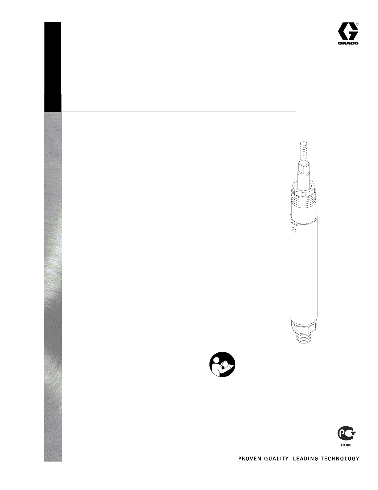
SEVERE–DUTY
Displacement Pumps
Part No. 222012, Series C (#2)
5000 psi (34.5 MPa, 345 bar) Maximum Working Pressure
0.554 in.@ (357.4 mm@) Effective Displacement Area
Part No. 222015, Series B (#5)
5000 psi (34.5 MPa, 345 bar) Maximum Working Pressure
0.443 in.@ (285.8 mm@) Effective Displacement Area
Part No. 222017, Series C (#7)
5000 psi (34.5 MPa, 345 bar) Maximum Working Pressure
0.370 in.@ (238.7 mm@) Effective Displacement Area
Part No. 222019, Series B (#9)
5000 psi (34.5 MPa, 345 bar) Maximum Working Pressure
0.277 in.@ (178.7 mm@) Effective Displacement Area
Part No. 239388, Series A (#2), with rod scraper
5000 psi (34.5 MPa, 345 bar) Maximum Working Pressure
0.554 in.@ (357.4 mm@) Effective Displacement Area
Part No. 948640, Series A (#0)
3000 psi (21 MPa, 210 bar) Maximum Working Pressure
0.884 in.@ (572.2 mm@) Effective Displacement Area
307944W
Part No. 948641, Series A (#1)
3000 psi (21 MPa, 210 bar) Maximum Working Pressure
0.740 in.@ (477.4 mm@) Effective Displacement Area
Severe-Duty Displacement Pumps have an abrasion and corrosionresistant displacement rod and cylinder. Refer to Technical Data
on page 13 for Wetted Parts information.
Contents
Warnings 2. . . . . . . . . . . . . . . . . . . . . . . . . . . . . . . . . . . . . .
Installation 5. . . . . . . . . . . . . . . . . . . . . . . . . . . . . . . . . . . . .
Service 6. . . . . . . . . . . . . . . . . . . . . . . . . . . . . . . . . . . . . . .
Parts 8. . . . . . . . . . . . . . . . . . . . . . . . . . . . . . . . . . . . . . . . .
Accessories 13. . . . . . . . . . . . . . . . . . . . . . . . . . . . . . . . . .
Dimensions 13. . . . . . . . . . . . . . . . . . . . . . . . . . . . . . . . . . .
Technical Data 13. . . . . . . . . . . . . . . . . . . . . . . . . . . . . . . .
Warranty 14. . . . . . . . . . . . . . . . . . . . . . . . . . . . . . . . . . . . .
Graco Information 14. . . . . . . . . . . . . . . . . . . . . . . . . . . . .
GRACO INC. P.O. BOX 1441 MINNEAPOLIS, MN 55440–1441
Copyright 2001, Graco Inc. is registered to I.S. EN ISO 9001
02403
Important Safety Instructions
Read all warnings and instructions in this manual.
Save these instructions.
Page 2

Symbols
Warning Symbol
WARNING
This symbol alerts you to the possibility of serious
injury or death if you do not follow the instructions.
WARNING
EQUIPMENT MISUSE HAZARD
Equipment misuse can cause the equipment to rupture or malfunction and result in serious injury.
INSTRUCTIONS
D This equipment is for professional use only.
D Read all instruction manuals, tags, and labels before operating the equipment.
D Use the equipment only for its intended purpose. If you are uncertain about usage, call your Graco
distributor.
D Do not alter or modify this equipment. Use only genuine Graco parts and accessories.
D Check equipment daily. Repair or replace worn or damaged parts immediately.
Caution Symbol
CAUTION
This symbol alerts you to the possibility of damage to
or destruction of equipment if you do not follow the
instructions.
D Do not exceed the maximum working pressure of the lowest rated system component.
D Route hoses away from traffic areas, sharp edges, moving parts, and hot surfaces. Do not expose
Graco hoses to temperatures above 180_F (82_C) or below –40_F (–40_C).
D Do not use the hoses to pull the equipment.
D Use only Graco approved hoses. Do not remove hose spring guards, which help protect the hose
from rupture caused by kinks or bends near the couplings.
D Use fluids and solvents that are compatible with the equipment wetted parts. Refer to the Techni-
cal Data section of all equipment manuals. Read the fluid and solvent manufacturer’s warnings.
D Wear hearing protection when operating this equipment.
D Comply with all applicable local, state, and national fire, electrical, and safety regulations.
MOVING PARTS HAZARD
Moving parts can pinch or amputate your fingers.
D Do not operate the equipment with the air motor plates removed.
D Keep clear of all moving parts when starting or operating the pump.
D Before checking or servicing the equipment, follow the Pressure Relief Procedure on page 4 to
prevent the equipment from starting unexpectedly.
2 307944
Page 3

WARNING
INJECTION HAZARD
Spray from the gun, hose leaks, or ruptured components can inject fluid into your body and cause
extremely serious injury, including the need for amputation. Splashing fluid in the eyes or on the skin
can also cause serious injury.
D Fluid injected into the skin might look like just a cut, but it is a serious injury. Get immediate surgi-
cal treatment.
D Do not point the spray gun at anyone or at any part of the body.
D Do not put your hand or fingers over the spray tip.
D Do not stop or deflect leaks with your hand, body, glove or rag.
D Do not “blow back” fluid; this is not an air spray system.
D Be sure the gun trigger safety operates before spraying.
D Lock the gun trigger safety when you stop spraying.
D Follow the Pressure Relief Procedure on page 4 whenever you: are instructed to relieve pres-
sure; stop spraying; clean, check, or service the equipment; and install or clean the spray tip.
D Tighten all fluid connections before operating the equipment.
D Check the hoses, tubes, and couplings daily. Replace worn, damaged, or loose parts immediately.
Permanently coupled hoses cannot be repaired; replace the entire hose.
FIRE AND EXPLOSION HAZARD
Improper grounding, poor ventilation, open flames, or sparks can cause a hazardous condition and
result in fire or explosion and serious injury.
D Ground the equipment and the object being sprayed. See Grounding on page 5.
D Provide fresh air ventilation to avoid the buildup of flammable fumes from solvents or the fluid
being sprayed.
D Keep the spray area free of debris, including solvent, rags, and gasoline.
D Before operating this equipment, electrically disconnect all equipment in the spray area.
D Before operating this equipment, extinguish all open flames or pilot lights in the spray area.
D Do not smoke in the spray area.
D Do not turn on or off any light switch in the spray area while operating or if fumes are present.
D Do not operate a gasoline engine in the spray area.
D If there is any static sparking while using the equipment, stop spraying immediately. Identify and
correct the problem.
307944 3
Page 4
TOXIC FLUID HAZARD
Hazardous fluid or toxic fumes can cause serious injury or death if splashed in the eyes or on the skin,
inhaled, or swallowed.
D Know the specific hazards of the fluid you are using.
D Store hazardous fluid in an approved container. Dispose of hazardous fluid according to all local,
state and national guidelines.
D Always wear protective eyewear, gloves, clothing and respirator as recommended by the fluid and
solvent manufacturer.
D Graco does not manufacture or supply any of the reactive chemical components that may be used
in this equipment and is not responsible for their effects. Graco assumes no responsibility for loss,
damage, expense or claims for personal injury or property damage, direct or consequential, arising
from the use of such chemical components.
Pressure Relief Procedure
WARNING
WARNING
4. Unlock the spray gun trigger safety.
INJECTION HAZARD
The system pressure must be manually
relieved to prevent the system from
starting or spraying accidentally. Fluid
under high pressure can be injected through the
skin and cause serious injury. To reduce the risk of
an injury from injection, splashing fluid, or moving
parts, follow the Pressure Relief Procedure
whenever you:
D are instructed to relieve the pressure,
D stop spraying,
D check or service any of the system equipment,
D or install or clean the spray tips.
1. Lock the spray gun trigger safety.
2. Shut off the power supply to the pump.
3. Close the bleed-type master air valve (required in
air-powered systems).
5. Hold a metal part of the gun firmly to the side of a
grounded metal pail, and trigger the gun to relieve
pressure.
6. Lock the spray gun trigger safety.
7. Open the fluid drain valve (required in your system); have a container ready to catch the drainage.
8. Leave the fluid drain valve open until you are ready
to spray again.
9. If you suspect that the spray tip or hose is com-
pletely clogged, or that pressure has not been fully
relieved after following the steps above, very
slowly loosen the tip guard retaining nut or hose
end coupling and relieve pressure gradually, then
loosen completely. Now clear the tip or hose.
4 307944
Page 5

Installation
General Information
NOTE:
D Reference numbers and letters in parentheses in
the text refer to the callouts in Figure 1 and the
parts drawing.
D Use Genuine Graco Parts and Accessories, avail-
able from your Graco distributor.
Grounding
WARNING
FIRE AND EXPLOSION HAZARD
Before operating the pump, ground the
system as explained below. Also read
the section FIRE AND EXPLOSION
HAZARD on page 3.
1. Pump: use a ground wire and clamp as shown in
your separate pump manual.
2. Air or hydraulic hoses: use only electrically conductive hoses.
3. Fluid hoses: use only electrically conductive fluid
hoses.
4. Air compressor or hydraulic supply: follow the
manufacturer’s recommendations.
5. Spray gun: ground by connecting the gun to a
properly grounded fluid hose and pump.
6. Fluid supply container: follow your local code.
7. Object being sprayed: follow your local code.
8. Solvent pails used when flushing: follow your local
code. Use only metal pails, which are conductive,
placed on a grounded surface. Do not place the
pail on a nonconductive surface, such as paper or
cardboard, which interrupts the grounding continuity.
9. To maintain grounding continuity when flushing or
relieving pressure, hold a metal part of the spray
gun firmly to the side of a grounded metal pail,
then trigger the gun.
307944 5
Page 6

Service
Displacement Pump Repair
WARNING
INJECTION HAZARD
To reduce the risk of serious injury,
follow the Pressure Relief Procedure
on page 4 before checking or servicing
any part of the system and whenever you are
instructed to relieve the pressure.
NOTE: Repair Kits are available. See the parts list for
your pump model. All kits (except 948651) include
eight shims (14*) for use on the piston, but use only
the number required. An asterisk behind a reference
number, for example (3*), indicates that this part is
included in the repair kit.
1. Solvent flush the pump if possible.
2. Follow the Pressure Relief Procedure on page
4, stopping the pump at the bottom of its stroke.
3. Disconnect all hoses from the pump.
*5
8
*4
*7
*10
2
3*
6*
4. Unscrew the displacement rod (1) from the air
motor connecting rod.
5. Screw the intake valve housing (24) out of the
cylinder (11). See Fig. 1. Disassemble and clean
the valve parts. Inspect the parts for damage or
wear. If the seat in the valve housing is chipped or
worn, replace the housing (24).
6. Loosen the packing nut (2).
7. Push down on the displacement rod (1) until you
can grasp the piston stud (20). Pull the displacement rod out the bottom of the cylinder (11).
Continued on the next page.
SERVICE NOTES:
All Pump Models except 239388: Torque to 50–60 ft-lb (70–80 NSm).
239388 Pump Model: Torque to 20–25 ft-lb (30–35 NSm).
Apply sealant. Torque to 200 in-lb (23 NSm).
Lips of v-packings must face down.
Torque to 50–60 ft-lb (70–80 NSm).
Lips of v-packings must face up.
Add shims (14*) required to make stack height 0.950–0.975 in.
(24.13–24.77 mm). For model 222017 add shims (14) required to
make stack height 0.960–0.975 in. (24.38–24.77 mm).
Parts for 239388 Pump Model only
15
*14
15
21
*22
24
11
1
06913B
13*
16*
18*
19*
20
30
33*
23*
12
Fig. 1
6 307944
Page 7

Service
8. Inspect the outer surface of the displacement rod
(1) and the polished inner surface of the cylinder
sleeve (12) for scoring or wear by running a finger
over the surface or holding the part up to a light at
an angle. Damage to these parts may cause
premature packing wear or leaking. If either part is
worn or scratched, replace it.
NOTE: If replacing the sleeve (12), be sure to install it
with the notched end up, and replace the o-ring (10*)
in the notch. If the old sleeve is hard to remove, contact your Graco representative.
9. Unscrew the piston stud (20) from the displacement rod (1). Remove the ball (13), shims (14),
backup washers (15), glands (16 and 19), and
v-packings (18). Clean all parts and inspect for
damage. If the seat on the piston stud (20) is
nicked or worn, replace it.
10. Remove the packing nut/wet-cup (2).
11. 239388 Pump Model only: Remove the seal
guard kit (5) and washer (8) from the packing
nut (2).
18. All Pump Models except 948640 and 948641:
Add shims (14*) below the top backup washer
(15*), using as many as necessary to obtain a total
packing stack height of 0.950–0.975 in.
(24.13–24.77 mm). For pump model 222017 use
stack height of 0.960–0.975 in. (24.38–24.77 mm).
19. Place the ball (13*) on the piston stud (20). Apply
liquid thread sealant to the piston threads and
screw the piston assembly into the displacement
rod (1), torquing it to 200 in-lb (23 N.m).
20. Lubricate the displacement rod (1), and guide it
through the bottom of the pump cylinder (11) and
carefully through the throat packings.
21. Install the o-ring (22*) on the intake valve housing
(24).
22. Place the ball (23*) on the seat of the intake valve
housing.
23. Slip the o-ring retainer (30) onto the intake housing
and align the holes in the two parts.
12. Remove the bearing (3), glands (4 and 7), and
v-packings (6) from the throat of the pump cylinder
(11). Clean all parts and inspect for damage.
13. Lubricate all packings before reassembling the
pump.
14. One at a time, place a male gland (7*), four PTFE
v-packings (6*), a female gland (4*), and the
bearing (3*) in the throat of the cylinder (11). Be
sure the lips of the v-packings face down in the
throat. See Fig. 1.
15. 239388 Pump Model only: Install the washer (8)
and seal guard kit (5) into the packing nut (2).
Pack the packing nut inside and outside with
Vaseliner. Use Vaseliner brand petroleum jelly
only.
16. Loosely install the packing nut (2).
17. One at a time, place a backup washer (15), a
female gland (19*), four PTFE v-packings (18*), a
male gland (16*), and a backup washer (15) on
the piston stud (20). Be sure the lips of the v-pack-
ings face up on the piston. See Fig. 1.
24. Compress spring (33*) on the ball (23*).
25. Install the ball stop pin (21) through the o-ring
retainer and intake valve housing (24), and screw
the housing into the pump cylinder (11). Torque
the housing to 50–60 ft-lb (70–80 NSm).
26. All Pump Models except 239388: Torque the
packing nut (2) to 50–60 ft-lb (70–80 NSm).
239388 Pump Model: Torque the packing nut (2)
to 20–25 ft-lb (30–35 NSm).
27. All Pump Models except 239388: Fill the packing
nut cavity with Throat Seal Liquid (TSL) for paints
and resins, or ISO Pump Oil (217374) for moisture
sensitive materials such as isocyanates.
28. Screw the displacement rod (1) into the air motor
connecting rod.
NOTE: If the ground wire was disconnected before
servicing, reconnect it before operating the pump.
Check that the entire system is properly grounded.
307944 7
Page 8

*3
*4
*6
*7
11
*10
12
Parts
Model 222012, Series C
2
1
†15
*14
*16
*18
*19
†15
*13
30†
†20
21
22*
*33
*23
24
02402B
Ref.
No. Part No. Description Qty.
1 181513 ROD, displacement; sst 1
2 192174 NUT, packing; cst 1
3* 188402 SPACER, packing; sst 1
4* 181725 GLAND, female; cst 1
6* 183757 V-PACKING; PTFE 4
7* 181726 GLAND, male; cst 1
10* 109115 O-RING; PTFE 1
11 181649 CYLINDER, pump; cst 1
12 181510 SLEEVE, cylinder; sst 1
13* 101823 BALL; 5/16 in. dia.; sst 1
14* 189314 SHIM; sst 8
15† 176107 WASHER, back-up; cst 2
16* 181664 GLAND, male; cst 1
18* 165104 V-PACKING; PTFE 4
19* 181663 GLAND, female; cst 1
20† 205383 STUD, piston; cst, w/carbide seat 1
21 165049 PIN, stop, ball; sst 1
22* 109176 O-RING; PTFE 1
23* 100064 BALL; 5/8 in. dia.; cst 1
24 220297 HOUSING, valve, intake;
cst, w/carbide seat 1
30† 185265 RETAINER, o-ring; sst 1
33* 510956 SPRING, compression 1
* These parts are also included in Repair Kit 236597, which
may be purchased separately.
† Keep these spare parts on hand to reduce down time.
Model 222015, Series B
Ref.
No. Part No. Description Qty.
1 181656 ROD, displacement; sst 1
2 192174 NUT, packing; cst 1
3* 181655 BEARING, sleeve; acetal 1
4* 181652 GLAND, female; cst 1
6* 183758 V-PACKING; PTFE 4
7* 181651 GLAND, male; cst 1
10* 109115 O-RING; PTFE 1
11 181649 CYLINDER, pump; cst 1
12 181509 SLEEVE, cylinder; sst 1
13* 101823 BALL; 5/16 in. dia.; sst 1
14* 188204 SHIM; sst 8
15† 176108 WASHER, back-up; cst 2
16* 181724 GLAND, male; cst 1
18* 183760 V-PACKING; PTFE 4
19* 181723 GLAND, female; cst 1
20† 205386 STUD, piston; cst, w/carbide seat 1
21 165049 PIN, stop, ball; sst 1
22* 109176 O-RING; PTFE 1
23* 100064 BALL; 5/8 in. dia.; cst 1
24 220297 HOUSING, valve, intake;
cst, w/carbide seat 1
30† 185265 RETAINER, o-ring; sst 1
33*@ 510956 SPRING, compression 1
* These parts are also included in Repair Kit 236598, which
may be purchased separately.
† Keep these spare parts on hand to reduce down time.
@ If this pump is being used in a VRHM system, spring
501095 is used. Purchase separately for repair.
8 307944
Page 9

Parts
Model 222017, Series C
Ref.
No. Part No. Description Qty.
1 181660 ROD, displacement; sst 1
2 192174 NUT, packing; cst 1
3* 181659 BEARING, sleeve; acetal 1
4* 181719 GLAND, female; cst 1
6* 183861 V-PACKING; PTFE 4
7* 181720 GLAND, male; cst 1
10* 109115 O-RING; PTFE 1
11 181649 CYLINDER, pump; cst 1
12 181508 SLEEVE, cylinder; sst 1
13* 101823 BALL; 5/16 in. dia.; sst 1
14* 188204 SHIM; sst 8
15† 164391 WASHER, back-up; cst 2
16* 181722 GLAND, male; cst 1
18* 183759 V-PACKING; PTFE 4
19* 181721 GLAND, female; cst 1
20† 205388 STUD, piston; cst, w/carbide seat 1
21 165049 PIN, stop, ball; sst 1
22* 109176 O-RING; PTFE 1
23* 100064 BALL; 5/8 in. dia.; cst 1
24 220297 HOUSING, valve, intake;
cst, w/carbide seat 1
30† 185265 RETAINER, o-ring; sst 1
33*@ 510956 SPRING, compression 1
* These parts are also included in Repair Kit 236595, which
may be purchased separately.
† Keep these spare parts on hand to reduce down time.
@ If this pump is being used in a VRHM system, spring
501095 is used. Purchase separately for repair.
Model 222019, Series B
Ref.
No. Part No. Description Qty.
1 181512 ROD, displacement; sst 1
2 192174 NUT, packing; cst 1
3* 181645 BEARING, sleeve; acetal 1
4* 181718 GLAND, female; cst 1
6* 183761 V-PACKING; PTFE 4
7* 181717 GLAND, male; cst 1
10* 109115 O-RING; PTFE 1
11 181649 CYLINDER, pump; cst 1
12 181507 SLEEVE, cylinder; sst 1
13* 101823 BALL; 5/16 in. dia.; sst 1
14* 189315 SHIM; sst 8
15† 176109 WASHER, back-up; cst 2
16* 181646 GLAND, male; cst 1
18* 165109 V-PACKING; PTFE 4
19* 181647 GLAND, female; cst 1
20† 207923 STUD, piston; cst, w/carbide seat 1
21 165049 PIN, stop, ball; sst 1
22* 109176 O-RING; PTFE 1
23* 100064 BALL; 5/8 in. dia.; cst 1
24 220297 HOUSING, valve, intake;
cst, w/carbide seat 1
30† 185265 RETAINER, o-ring; sst 1
33* 510956 SPRING, compression 1
* These parts are also included in Repair Kit 236596, which
may be purchased separately.
† Keep these spare parts on hand to reduce down time.
307944 9
Page 10

Parts
*5
*3
*4
*6
*7
11
*10
Model 239388, Series A
8
2
1
†15
*14
*16
*18
*19
Ref.
No. Part No. Description Qty.
1 181513 ROD, displacement; sst 1
2 192174 NUT, packing; cst 1
3* 15A730 SPACER, packing; sst 1
4* 181725 GLAND, female; cst 1
5* 113938 KIT, seal guard 1
6* 113937 V-PACKING; carbon-filled PTFE 4
7* 181726 GLAND, male; cst 1
8 192175 WASHER, support 1
10* 109115 O-RING; PTFE 1
11 181649 CYLINDER, pump; cst 1
12 181510 SLEEVE, cylinder; sst 1
13* 101823 BALL; 5/16 in. dia.; sst 1
14* 189314 SHIM; sst 8
15† 176107 WASHER, back-up; cst 2
16* 181664 GLAND, male; cst 1
18* 165104 V-PACKING; PTFE 4
19* 181663 GLAND, female; cst 1
20† 205383 STUD, piston; cst, w/carbide seat 1
21 165049 PIN, stop, ball; sst 1
22* 109176 O-RING; PTFE 1
23* 100064 BALL; 5/8 in. dia.; cst 1
24 220297 HOUSING, valve, intake;
cst, w/carbide seat 1
30† 185265 RETAINER, o-ring; sst 1
33* 510956 SPRING, compression 1
12
†20
21
†15
*13
*33
*23
24
* These parts are also included in Repair Kit 239387, which
may be purchased separately.
† Keep these spare parts on hand to reduce down time.
30†
22*
06911B
10 307944
Page 11

*3
a
*4
*6
*7
11
*10
5*
Parts
Model 948641, Series A
2
1
9†
†15
8
*16
*18
17*
Ref.
No. Part No. Description Qty.
1 624925 ROD, displacement; sst 1
2 624888 NUT, packing; cst 1
3* 624926 BEARING, throat; acetal 1
4* 624931 GLAND, female; cst 1
5* 513427 V-PACKING; UHMWPE 2
6* 513429 V-PACKING; PTFE 2
7* 624932 GLAND, male; cst 1
8 167671 PIN, straight 1
9† 100063 PIN, cotter 2
10* 167668 GASKET; PTFE 1
11 624890 CYLINDER, pump; cst 1
12 624927 SLEEVE, cylinder; sst 1
13* 116166 BALL; carbide 1
15* 624928 RETAINER, packing; cst 1
16* 624929 GLAND, male; cst 1
17* 513430 V-PACKING; UHMWPE 2
18* 513428 V-PACKING; PTFE 2
19* 624930 GLAND, female; cst 1
20† 948639 STUD, piston; cst, w/carbide seat 1
21 167662 PIN, stop, ball; sst 1
22* 165053 O-RING; PTFE 1
23* 101859 BALL; sst 1
24 207357 HOUSING, valve, intake;
cst, w/carbide seat 1
30† 185265 RETAINER, o-ring; sst 1
12
21
*19
*13
†20
*23
24
* These parts are also included in Repair Kit 948651, which
may be purchased separately.
† Keep these spare parts on hand to reduce down time.
30†
22*
ti3987
307944 11
Page 12

*3
*4
*6
*7
11
*10
5*
Parts
Model 948640, Series A
2
1
9†
25
8
†15
*7
*6
5*
Ref.
No. Part No. Description Qty.
1 624891 ROD, displacement; sst 1
2 624888 NUT, packing; cst 1
3* 624889 BEARING, throat; acetal 1
4* 625448 GLAND, female; cst 2
5* 108454 V-PACKING; UHMWPE 4
6* 167665 V-PACKING; PTFE 4
7* 183644 GLAND, male; cst 2
8 167671 PIN, straight 1
9† 100063 PIN, cotter 2
10* 167668 GASKET; PTFE 1
11 624890 CYLINDER, pump; cst 1
12 624886 SLEEVE, cylinder; sst 1
13* 101822 BALL; sst 1
15* 167672 RETAINER, packing; cst 1
20† 949117 STUD, piston; cst, w/carbide seat 1
21 167662 PIN, stop, ball; sst 1
22* 165053 O-RING; PTFE 1
23* 101859 BALL; sst 1
24 207357 HOUSING, valve, intake;
cst, w/carbide seat 1
25 625999 GUIDE, ball 1
30† 167663 RETAINER, o-ring; sst 1
* These parts are also included in Repair Kit 948650, which
may be purchased separately.
† Keep these spare parts on hand to reduce down time.
12
21
*4
*13
†20
*23
24
30†
22*
ti3986a
12 307944
Page 13

Accessories
Dimensions
Must be ordered separately
ISO Pump Oil
Use in wet-cup instead of Throat Seal Liquid (TSL)
when pumping moisture-sensitive fluids.
217374 1 pint container – quantity of 1
218656 1 gallon containers – quantity of 4
Hydra-Catt Wrench 176881
For tightening packing nut and intake valve.
UHMWPE/PTFE Packing Conversion Kits
To convert the pump to ultra-high molecular weight
polyethylene and PTFE packings. Includes instructions.
222237 For pump model 222015
222235 For pump model 222019
222236 For pump model 222012
222234 For pump model 222017
With connecting rod at bottom of stroke.
1/2–20 unf
1 3/4–20 un
3/8 npt(f)
18.62 in.
(473.0 mm)
12.50 in.
(317.5 mm)
3/4 npt(m)
Technical Data
Wetted parts Stainless Steel, Tungsten Carbide,. . . . . . . . . . . . . . . . . . . . . . . . . . . . . . . . . . . . . .
Ultra–High Molecular Weight Polyethylene (948640 and 948641 only)
Displ. Pump
Part No.
222012 and
239388
222015 5000 (34.5, 345) 0.887 (572.29) 0.442 (285.18) –0.7 0.443 (285.81) 4.75 (120.7)
222017 5000 (34.5, 345) 0.740 (477.42) 0.371 (239.37) 1.00 0.370 (238.71) 4.75 (120.7)
222019 5000 (34.5, 345) 0.554 (357.44) 0.277 (178.72) 0.00 0.277 (178.72) 4.75 (120.7)
948640 3000 (21, 210) 1.767 (1140.1) 0.887 (572.6) 0.4 0.884 (570.0) 4.75 (120.7)
948641 3000 (21, 210) 1.480 (954.76) 0.740 (477.7) .07 0.740 (477.4) 4.75 (120.7)
Maximum Working Pressure
psi (MPa, bar)
5000 (34.5, 345) 1.107 (714.20) 0.544 (350.99) 0.16 0.554 (357.44) 4.75 (120.7)
Cylinder ID
Area
in.@ (mm@)
Chrome and Zinc Plating, Carbon Steel,PTFE,
Displ. Rod OD
Area
in.@ (mm@)
% of
Diff.
Effective Area
in.@ (mm@)
Maximum
Stroke
in. (mm)
02403
307944 13
Page 14

Graco Standard Warranty
Graco warrants all equipment referenced in this document which is manufactured by Graco and bearing its name to be free from
defects in material and workmanship on the date of sale to the original purchaser for use. With the exception of any special, extended,
or limited warranty published by Graco, Graco will, for a period of twelve months from the date of sale, repair or replace any part of the
equipment determined by Graco to be defective. This warranty applies only when the equipment is installed, operated and maintained
in accordance with Graco’s written recommendations.
This warranty does not cover, and Graco shall not be liable for general wear and tear, or any malfunction, damage or wear caused by
faulty installation, misapplication, abrasion, corrosion, inadequate or improper maintenance, negligence, accident, tampering, or substitution of non–Graco component parts. Nor shall Graco be liable for malfunction, damage or wear caused by the incompatibility of
Graco equipment with structures, accessories, equipment or materials not supplied by Graco, or the improper design, manufacture,
installation, operation or maintenance of structures, accessories, equipment or materials not supplied by Graco.
This warranty is conditioned upon the prepaid return of the equipment claimed to be defective to an authorized Graco distributor for
verification of the claimed defect. If the claimed defect is verified, Graco will repair or replace free of charge any defective parts. The
equipment will be returned to the original purchaser transportation prepaid. If inspection of the equipment does not disclose any defect
in material or workmanship, repairs will be made at a reasonable charge, which charges may include the costs of parts, labor, and
transportation.
THIS WARRANTY IS EXCLUSIVE, AND IS IN LIEU OF ANY OTHER WARRANTIES, EXPRESS OR IMPLIED, INCLUDING BUT
NOT LIMITED TO WARRANTY OF MERCHANTABILITY OR WARRANTY OF FITNESS FOR A PARTICULAR PURPOSE.
Graco’s sole obligation and buyer’s sole remedy for any breach of warranty shall be as set forth above. The buyer agrees that no other
remedy (including, but not limited to, incidental or consequential damages for lost profits, lost sales, injury to person or property, or any
other incidental or consequential loss) shall be available. Any action for breach of warranty must be brought within two (2) years of the
date of sale.
GRACO MAKES NO WARRANTY, AND DISCLAIMS ALL IMPLIED WARRANTIES OF MERCHANTABILITY AND FITNESS FOR
A PARTICULAR PURPOSE, IN CONNECTION WITH ACCESSORIES, EQUIPMENT, MATERIALS OR COMPONENTS SOLD
BUT NOT MANUFACTURED BY GRACO. These items sold, but not manufactured by Graco (such as electric motors, switches,
hose, etc.), are subject to the warranty, if any, of their manufacturer. Graco will provide purchaser with reasonable assistance in making any claim for breach of these warranties.
In no event will Graco be liable for indirect, incidental, special or consequential damages resulting from Graco supplying equipment
hereunder, or the furnishing, performance, or use of any products or other goods sold hereto, whether due to a breach of contract,
breach of warranty, the negligence of Graco, or otherwise.
FOR GRACO CANADA CUSTOMERS
The parties acknowledge that they have required that the present document, as well as all documents, notices and legal proceedings
entered into, given or instituted pursuant hereto or relating directly or indirectly hereto, be drawn up in English. Les parties reconnaissent avoir convenu que la rédaction du présente document sera en Anglais, ainsi que tous documents, avis et procédures judiciaires
exécutés, donnés ou intentés à la suite de ou en rapport, directement ou indirectement, avec les procedures concernées.
Graco Information
TO PLACE AN ORDER, contact your Graco distributor, or call this number to identify the distributor closest to you:
1–800–328–0211 Toll Free
612–623–6921
612–378–3505 Fax
All written and visual data contained in this document reflects the latest product information available at the time of publication.
Graco reserves the right to make changes at any time without notice.
MM 307944
International Offices: Belgium, China, Japan, Korea
Graco Headquarters: Minneapolis
GRACO INC. P.O. BOX 1441 MINNEAPOLIS, MN 55440–1441
www.graco.com
PRINTED IN U.S.A. 307944 October 1988, Revised 07/2005
14 307944
 Loading...