

Page 1
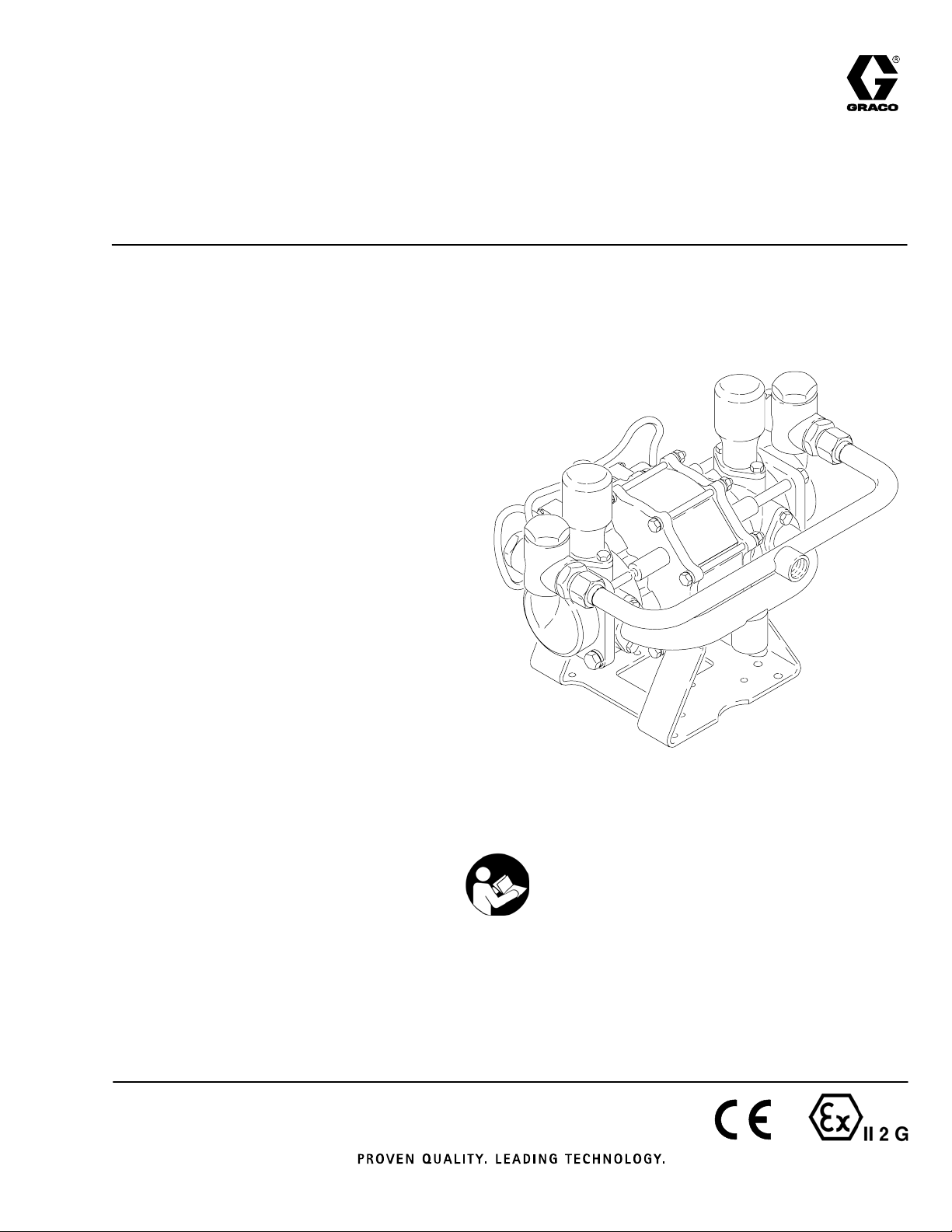
Instructions–Parts List
STAINLESS STEEL OR CARBON STEEL
Air–Powered Gluttonr
Pumps
100 psi (0.7 MPa, 7 bar) Maximum Incoming Air Pressure
400 Series Pumps
400 psi (2.8 MPa, 28 bar) Maximum Fluid Working Pressure
Model 220663, Series D
Model 237008, Series A
Carbon steel pumps*
Model 220666, Series D
Model 237011, Series A
Stainless steel pumps*
Electro-polished for use with waterborne coatings
1200 Series Pumps
1200 psi (8 MPa, 83 bar) Maximum
Fluid Working Pressure
Model 220664, Series D
Model 237009, Series A
Carbon steel pumps*
307843ZAF
EN
Model 220667, Series D
Model 237012, Series A
Stainless steel pumps*
Electro-polished for use with waterborne coatings
2500 Series Pumps
2500 psi (17 MPa, 170 bar) Maximum Fluid
Working Pressure
Model 220665, Series D
Model 237010, Series A
Carbon steel pumps*
Model 220668, Series D
Model 237013, Series A
Stainless steel pumps*
Electro-polished for use with waterborne coatings
*See TECHNICAL DATA on pages 44 through 46
for a complete materials list.
Important Safety Instructions
Read all warnings and instructions in this manual.
Save these instructions.
Page 2

Table of Contents
Warnings 3. . . . . . . . . . . . . . . . . . . . . . . . . . . . . . . . . . . . . . . . . . . . . . . . . . . . . . . . . . . . . . . . . . . . . . . . . . . . . . . . . . . . . . . . . .
Installation 6. . . . . . . . . . . . . . . . . . . . . . . . . . . . . . . . . . . . . . . . . . . . . . . . . . . . . . . . . . . . . . . . . . . . . . . . . . . . . . . . . . . . . . . . .
Operation 10. . . . . . . . . . . . . . . . . . . . . . . . . . . . . . . . . . . . . . . . . . . . . . . . . . . . . . . . . . . . . . . . . . . . . . . . . . . . . . . . . . . . . . . .
Troubleshooting 12. . . . . . . . . . . . . . . . . . . . . . . . . . . . . . . . . . . . . . . . . . . . . . . . . . . . . . . . . . . . . . . . . . . . . . . . . . . . . . . . . . .
Maintenance 14. . . . . . . . . . . . . . . . . . . . . . . . . . . . . . . . . . . . . . . . . . . . . . . . . . . . . . . . . . . . . . . . . . . . . . . . . . . . . . . . . . . . . .
Service 15. . . . . . . . . . . . . . . . . . . . . . . . . . . . . . . . . . . . . . . . . . . . . . . . . . . . . . . . . . . . . . . . . . . . . . . . . . . . . . . . . . . . . . . . . .
Parts Drawing and List
400 Series Carbon Steel Pumps, Models 220663 and 237008 24. . . . . . . . . . . . . . . . . . . . . . . . . . . . . . . . . . . . . . .
400 Series Stainless Steel Pumps, Models 220666 and 237011 26. . . . . . . . . . . . . . . . . . . . . . . . . . . . . . . . . . . . . .
1200 Series Carbon Steel Pumps, Models 220664 and 237009 28. . . . . . . . . . . . . . . . . . . . . . . . . . . . . . . . . . . . . .
1200 Series Stainless Steel Pumps, Models 220667 and 237012 30. . . . . . . . . . . . . . . . . . . . . . . . . . . . . . . . . . . . .
2500 Series Carbon Steel Pumps, Models 220665 and 237010 32. . . . . . . . . . . . . . . . . . . . . . . . . . . . . . . . . . . . . .
2500 Series Stainless Steel Pumps, Models 220668 and 237013 34. . . . . . . . . . . . . . . . . . . . . . . . . . . . . . . . . . . . .
Air Control Valve 220902 36. . . . . . . . . . . . . . . . . . . . . . . . . . . . . . . . . . . . . . . . . . . . . . . . . . . . . . . . . . . . . . . . . . . . . . . .
Pilot Valve 221133 37. . . . . . . . . . . . . . . . . . . . . . . . . . . . . . . . . . . . . . . . . . . . . . . . . . . . . . . . . . . . . . . . . . . . . . . . . . . . .
Repair and Conversion Kits 38. . . . . . . . . . . . . . . . . . . . . . . . . . . . . . . . . . . . . . . . . . . . . . . . . . . . . . . . . . . . . . . . . . . . . . . . .
Filter, Regulator, Lubricator Kit 222345 41. . . . . . . . . . . . . . . . . . . . . . . . . . . . . . . . . . . . . . . . . . . . . . . . . . . . . . . . . . . . . . .
Drum Cover Kit 222655 42. . . . . . . . . . . . . . . . . . . . . . . . . . . . . . . . . . . . . . . . . . . . . . . . . . . . . . . . . . . . . . . . . . . . . . . . . . . .
Return Tube Kit 223319 42. . . . . . . . . . . . . . . . . . . . . . . . . . . . . . . . . . . . . . . . . . . . . . . . . . . . . . . . . . . . . . . . . . . . . . . . . . . .
Suction Kit 208259 43. . . . . . . . . . . . . . . . . . . . . . . . . . . . . . . . . . . . . . . . . . . . . . . . . . . . . . . . . . . . . . . . . . . . . . . . . . . . . . . .
Technical Data and Performance Chart
400 Series Pumps 44. . . . . . . . . . . . . . . . . . . . . . . . . . . . . . . . . . . . . . . . . . . . . . . . . . . . . . . . . . . . . . . . . . . . . . . . . . . . .
1200 Series Pumps 45. . . . . . . . . . . . . . . . . . . . . . . . . . . . . . . . . . . . . . . . . . . . . . . . . . . . . . . . . . . . . . . . . . . . . . . . . . . .
2500 Series Pumps 46. . . . . . . . . . . . . . . . . . . . . . . . . . . . . . . . . . . . . . . . . . . . . . . . . . . . . . . . . . . . . . . . . . . . . . . . . . . .
Dimensional Drawing 47. . . . . . . . . . . . . . . . . . . . . . . . . . . . . . . . . . . . . . . . . . . . . . . . . . . . . . . . . . . . . . . . . . . . . . . . . . . . . .
Mounting Hole Layout 47. . . . . . . . . . . . . . . . . . . . . . . . . . . . . . . . . . . . . . . . . . . . . . . . . . . . . . . . . . . . . . . . . . . . . . . . . . . . . .
Graco Standard Warranty 48. . . . . . . . . . . . . . . . . . . . . . . . . . . . . . . . . . . . . . . . . . . . . . . . . . . . . . . . . . . . . . . . . . . . . . . . . .
Graco Information 48. . . . . . . . . . . . . . . . . . . . . . . . . . . . . . . . . . . . . . . . . . . . . . . . . . . . . . . . . . . . . . . . . . . . . . . . . . . . . . . . .
2 307843
Page 3
Warnings
Warning Symbol
WARNING
This symbol alerts you to the possibility of serious
injury or death if you do not follow the instructions.
WARNING
SKIN INJECTION HAZARD
Spray from the gun, leaks or ruptured components can inject fluid into your body and cause extremely
serious injury, including the need for amputation. Fluid splashed in the eyes or on the skin can also
cause serious injury.
D Fluid injected into the skin might look like just a cut, but it is a serious injury. Get immediate
surgical treatment.
D Do not point the gun at anyone or at any part of the body.
D Do not put your hand or fingers over the spray tip.
D Do not stop or deflect leaks with your hand, body, glove or rag.
Caution Symbol
CAUTION
This symbol alerts you to the possibility of damage to
or destruction of equipment if you do not follow the
instructions.
D Do not “blow back” fluid; this is not an air spray system.
D Always have the tip guard and the trigger guard on the gun when spraying.
D Check the gun diffuser operation weekly. Refer to the gun manual.
D Be sure the gun trigger safety operates before spraying.
D Lock the gun trigger safety when you stop spraying.
D Follow the Pressure Relief Procedure on page 10 whenever you: are instructed to relieve pres-
sure; stop spraying; clean, check, or service the equipment; and install or clean the spray tip.
D Tighten all fluid connections before operating the equipment.
D Check the hoses, tubes, and couplings daily. Replace worn or damaged parts immediately. Perma-
nently coupled hoses cannot be repaired; replace the entire hose.
D Use only Graco approved hoses. Do not remove the spring guard that is used to help protect the
hose from rupture caused by kinks or bends near the couplings.
307843 3
Page 4
INSTRUCTIONS
WARNING
EQUIPMENT MISUSE HAZARD
Equipment misuse can cause the equipment to rupture or malfunction and result in serious injury.
D This equipment is for professional use only.
D Read all instruction manuals, tags, and labels before operating the equipment.
D Use the equipment only for its intended purpose. If you are uncertain about usage, call your Graco
distributor.
D Do not alter or modify this equipment. Use only genuine Graco parts and accessories.
D Check equipment daily. Repair or replace worn or damaged parts immediately.
D Do not exceed the maximum working pressure of the lowest rated system component. Refer to the
Technical Data section on pages 44 through 46 for the maximum working pressure of this equipment.
D Use fluids and solvents which are compatible with the equipment wetted parts. Refer to the Tech-
nical Data section of all equipment manuals. Read the fluid and solvent manufacturer’s warnings.
D Do not use hoses to pull equipment.
D Route hoses away from traffic areas, sharp edges, moving parts, and hot surfaces. Do not expose
Graco hoses to temperatures above 82_C (180_F) or below –40_C (–40_F).
D Do not lift pressurized equipment.
D Comply with all applicable local, state, and national fire, electrical, and safety regulations.
D Never place your hands on or near the pump fluid inlet. Powerful suction could cause serious
bodily injury.
MOVING PARTS HAZARD
Moving parts can pinch or amputate your fingers or other body parts.
D Keep clear of all moving parts when starting or operating the equipment.
D Before servicing the equipment, follow the Pressure Relief Procedure on page 10 to prevent the
equipment from starting unexpectedly.
D Never operate the motor with the pump housing removed.
4 307843
Page 5
WARNING
FIRE AND EXPLOSION HAZARD
Improper grounding, poor ventilation, open flames, or sparks can cause a hazardous condition and
result in a fire or explosion and serious injury.
D Ground the equipment and the object being sprayed. See Grounding on page 7.
D Proper hose grounding continuity is essential in maintaining a grounded spray/dispense system.
Check the electrical resistance of your air and fluid hoses at least once a week. If your hose does
not have a tag on it that specifies the maximum electrical resistance, contact the hose supplier or
manufacturer for the maximum resistance limits. Use a resistance meter in the appropriate range
for your hose to check the resistance. If the resistance exceeds the recommended limits, replace it
immediately.
D If there is any static sparking or you feel an electric shock while using this equipment, stop spray-
ing immediately. Do not use the equipment until you identify and correct the problem.
D Provide fresh air ventilation to avoid the buildup of flammable fumes from solvents or the fluid
being sprayed.
D Keep the spray area free of debris, including solvent, rags, and gasoline.
D Electrically disconnect all equipment in the spray area.
D Extinguish all open flames or pilot lights in the spray area.
D Do not smoke in the spray area.
D Do not turn on or off any light switch in the spray area while operating or if fumes are present.
D Do not operate a gasoline engine in the spray area.
HAZARDOUS FLUIDS
Hazardous fluid or toxic fumes can cause serious injury or death if splashed in the eyes or on the skin,
inhaled, or swallowed.
D Be sure all fluids and solvents used are chemically compatible with the wetted parts shown in the
TECHNICAL DATA for your pump model. Always read the fluid and solvent manufacturer’s literature before using the fluid or solvent in this pump.
D Know the specific hazards of the fluid you are using.
D Store hazardous fluid in an approved container. Dispose of hazardous fluid according to all local,
state and national guidelines.
D Always wear protective eyewear, gloves, clothing and respirator as recommended by the fluid and
solvent manufacturer.
D Provide for safe piping and disposal of exhaust air.
D Secure the fluid outlet house tightly into the receiving container to prevent the hose from coming
loose and creating a fluid spill.
D Provide proper ventilation in accordance with accepted industry standards and government regula-
tions.
United States Government safety standards have been adopted under the Occupational Safety and Health Act. You
should consult these standards – particularly the General Standards, Part 1910, and the Construction Standards,
Part 1926.
307843 5
Page 6
Installation
Mounting the Pump
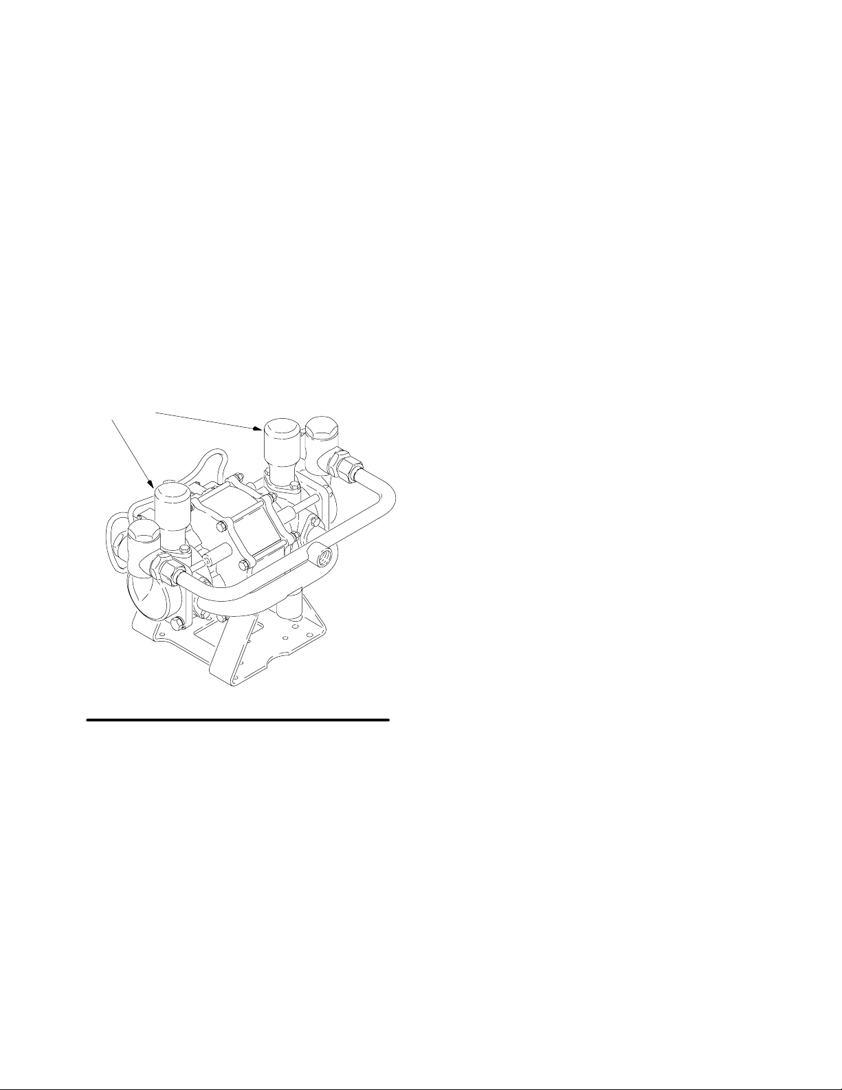
D 400 and 1200 Series Pumps: Mount the pump
with the accumulators in the top position as shown
in Fig. 1. The accumulators must be in the position
shown or the pump will not prime.
D Be sure the pump is securely bolted to its mounting
and that the mounting can support the weight of the
pump, hoses, and stress caused during operation.
D The outlet manifold can be removed and turned 180
degrees to change the direction of the outlet and
ease installation, as shown in Fig. 3.
accumulators
General Information
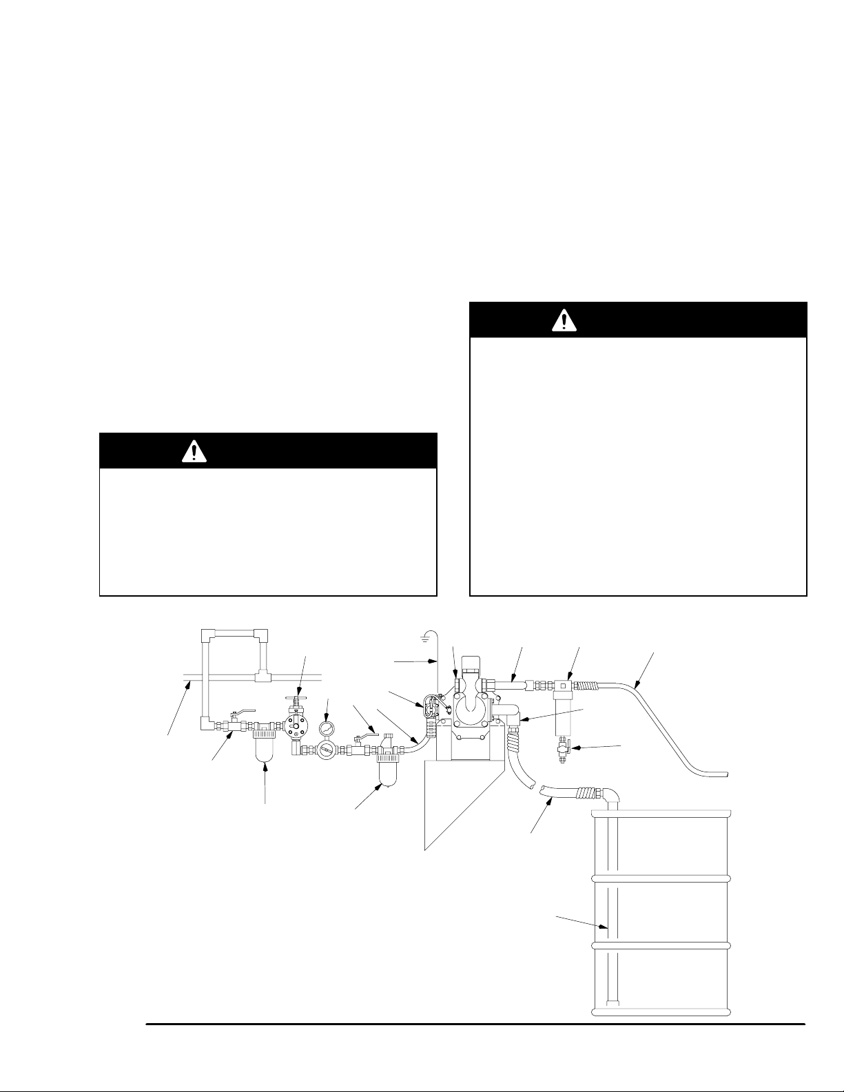
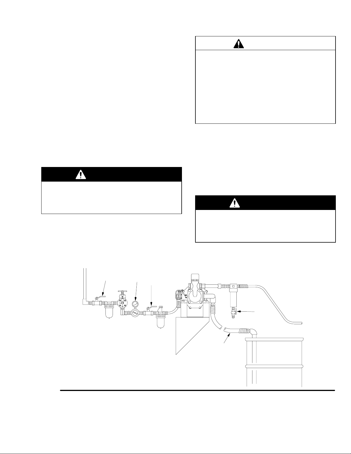
D The installation shown in Fig. 4 is only a guide for
selecting and installing system components. Contact your Graco distributor for assistance in planning a system to suit your needs.
D See pages 38 through 43 for accessories and kits
available from Graco. Always use Genuine Graco
Parts and Accessories.
D Use a thread sealant compatible with the fluid being
pumped on all male pipe threads. Tighten all connections firmly to avoid air or fluid leaks.
D Reference numbers and letters in parentheses in
the text refer to the figure illustrations.
Fig. 1
6 307843
02321
Page 7
Installation
Grounding
WARNING
This pump must be grounded. The steps for
grounding may differ from the way you ground
other pumps. Carefully read and follow these
grounding instructions. See FIRE AND EXPLO-
SION HAZARD on page 5 before you operate the
pump.
Static electricity is created by the high-velocity flow of
fluid through the pump and hose. If every part of the
equipment is not properly grounded, sparking may occur. To reduce the risk of static sparking, ground the
pump and all other equipment used or located in the
pumping area. Check your local electrical code for detailed grounding instructions for your area and type of
equipment. Ground all of the following equipment:
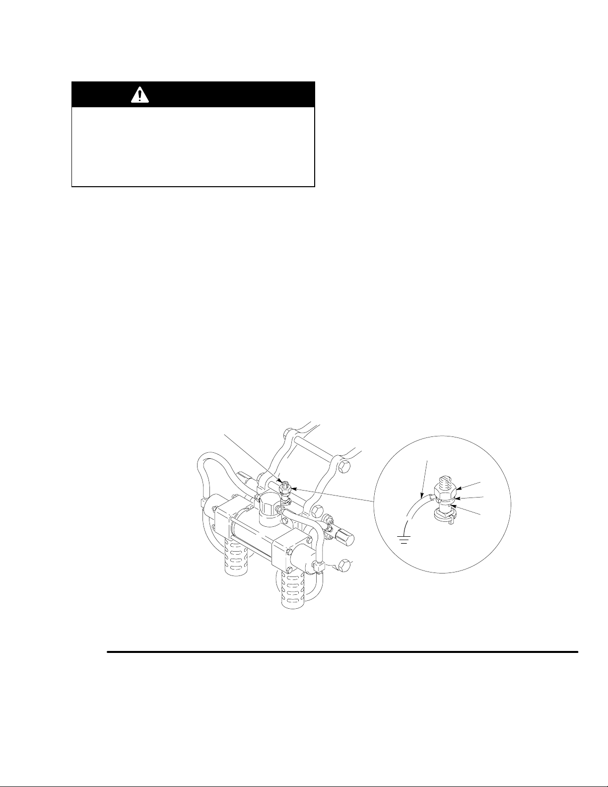
D Pump: use a ground wire and clamp as shown in
Fig. 2.
D Fluid and air hoses: use only grounded hoses with
a maximum of 500 feet (150 m) combined hose
length to ensure grounding continuity.
D Air Compressor: Follow the manufacturer’s recom-
mendations.
D Spray gun or dispensing valve: Obtain grounding
through connection to a properly grounded fluid
hose and pump.
D Fluid supply container: Follow the local code.
D Object being sprayed: Follow the local code.
D All solvent pails used when flushing: Follow the
local code. Use only metal pails, which are conductive. Do not place the pail on a non-conductive
surface, such as paper or cardboard, which interrupts the grounding continuity.
To ground the pump: Loosen the grounding lug locknut (W) and washer (X). Insert one end of a 12 ga (1.5
mm@) minimum ground wire (Y) into the slot (Z) of the
grounding lug, and tighten the locknut securely. Connect the clamp end of the ground wire to a true earth
ground. To order a ground wire and clamp, order Part
No. 222011.
Fig. 2
grounding lug
Y
W
X
Z
02322
307843 7
Page 8

5
Installation
Connect the Fluid Lines
1. Use grounded fluid hoses.
a. The pump fluid outlet (J) on the 400 and
1200 Series Pumps is 1 npt(f) .
b. The pump fluid outlet (J) on the 2500 Series
Pump is 3/4 npt(f).
2. Install a fluid filter (F) and drain valve (E) near the
fluid outlet. See Fig. 3.
WARNING
A fluid drain valve (E) is required in your system to
relieve pressure in the fluid outlet hose (H) if the
hose becomes plugged. See Fig. 3. Install a drain
valve close to the pump’s fluid outlet. The drain
valve reduces the risk of property damage or
serious bodily injury, including splashing in the eyes
or on the skin, or contamination from hazardous
fluids.
3. Install a control device, such as a gun, dispensing
valve, or shutoff valve, on the grounded fluid
hose (H).
Connect the Fluid Suction Line
CAUTION
The pump must be suction fed in order to operate
properly. Pressure feeding or exceeding 15 psi (104
kPa, 1.04 bar) maximum fluid inlet pressure may
cause premature bellows seal failure.
Connect the fluid suction hose (S) to the pump fluid
inlet (M). See Fig. 4.
D The pump fluid inlet (M) is 1.25 npt(f).
D The maximum suction lift is 15 ft (4.57m) for the
400 Series and 1200 Series Pumps, and 6 ft (1.83
m) for the 2500 Series Pump.
WARNING
SUCTION HAZARD
Never place your hands on or near the pump fluid
inlet. Powerful suction could cause serious bodily
injury.
Fig. 3
J
H
F
M
E
0232
8 307843
Page 9
Installation
3
Connect the Air Lines
1. Install the air line accessories to the left of the
pump as shown in Fig. 4. Mount these accessories
on the wall or on a bracket. Be sure the air line
supplying the accessories is grounded.
2. Install a flexible air hose between the accessories
and the 1/2 in. npt(f) air inlet (G). Use a minimum
1/2 in. ID air hose.
3. Install an air line lubricator (B) upstream from the
pump air inlet for automatic pump lubrication.
4. Install a pump runaway valve (T) to sense when
the pump is running too fast and shut off the air
supply to the motor. To order a pump runaway
valve, order Part No. 224040.
5. Install an air regulator (D) to control air inlet pressure.
WARNING
A bleed-type master air valve (C) is required in
your system to relieve air trapped between this
valve and the pump after the air regulator is closed.
Trapped air can cause the pump to cycle unexpectedly, which could result in serious bodily injury,
including splashing in the eyes, injury from moving
parts, or contamination from hazardous fluids.
6. Install one bleed-type master air valve (C) downstream from the air regulator and use it to relieve
trapped air. Locate the other master air valve upstream from all air line accessories and use it to
isolate the accessories during cleaning and repair.
7. Install an air line filter (A) to remove harmful dirt
and moisture from your compressed air supply.
8. Install a grounded air supply line (P) with a minimum 1/2 in. ID. See Fig. 4.
Ventilate the Air Exhaust
WARNING
Improper handling of hazardous fluids or inhaling
their vapors can cause serious bodily injury, even
death. For your safety, it is imperative that you read
all product warning labels and Material Safety Data
Sheets (MSDS) for the fluids you are using. An
MSDS can be obtained from your fluid suppliers. It
is also important that you read and understand the
warnings and precautions regarding HAZARDOUS
FLUID HAZARD on page 5 before you operate.
All systems using hazardous fluid in enclosed
areas or within buildings should have a properly
designed and installed ventilation system. Consult
your local building code and other industrial and
governmental standards for proper design criteria.
K
C
KEY
A Air line filter
B Air line lubricator
C Bleed-type master air valve
D Air regulator
E Fluid drain valve
F Fluid filter
G Pump air inlet
H Grounded fluid line
J Outlet manifold
Fig. 4
T
D
AB
K Main air line
L Ground wire
M Intake manifold
N Glutton pump
P Grounded air line
R Fluid supply
S Fluid suction hose
T Runaway valve
L
G
C
P
N
JF
M
E
S
R
H
0232
307843 9
Page 10
Operation
Pressure Relief Procedure
WARNING
The system pressure must be manually relieved to
prevent the system from starting or spraying accidentally. To reduce the risk of an injury from accidental spray from the gun, splashing fluid, or
moving parts, always follow the Pressure Relief
Procedure whenever you
D are instructed to relieve the pressure
D Stop spraying
D Check or service any of the system equipment
D install or clean the spray nozzle.
1. * Engage the spray gun or dispensing valve safety
latch.
2. Shut off the air supply.
3. * Disengage the gun or dispensing valve safety
latch.
4. * Hold a metal part of the gun or valve firmly to a
grounded metal waste container and trigger it to
relieve the fluid pressure.
5. * Engage the safety latch again.
6. Open the pump drain valve (required in system),
and have a container ready to catch the drainage.
7. Leave the drain valve open until you are ready to
spray again.
* Applies only when using a spray gun or dispensing
valve.
Start and Adjust the Pump
NOTE: Check all fittings to be sure they are tight. Be
sure to use a thread sealant compatible with the fluid
being pumped on all male pipe threads.
1. Place the suction hose (S) in the fluid to be
pumped. See Fig. 5.
2. Close the fluid drain valve (E).
3. With the air regulator (D) closed, open both bleedtype master air valves (C).
4. Open the fluid control device while continuing with
the following steps.
5. Slowly open the air regulator (D). Adjust it until the
pump runs smoothly.
6. Allow the pump to cycle slowly until all air is
pushed out of the lines (the fluid will be flowing in a
steady stream from the fluid outlet) and the pump
is primed.
WARNING
To reduce the risk of component rupture, which
could cause serious bodily injury, never exceed
100 psi (0.7 MPa, 7 bar) air supply pressure to the
pump. Read the warning section EQUIPMENT
MISUSE HAZARD on page 4.
If you suspect that the spray tip, nozzle, or hose is
clogged or that pressure has not been fully relieved
after following the steps above, very slowly loosen the
hose end coupling and relieve pressure gradually, then
loosen completely, then clear the tip, nozzle, or hose
obstruction.
Flush the Pump Before First Use
WARNING
To reduce the risk of fluid injection injury, static
sparking and splashing, read and follow Flushing
Safety under FIRE OR EXPLOSION HAZARD on
page 5.
The pump was tested with lightweight oil, which is left
in to protect the pump parts. If this solution could contaminate the fluid you are pumping, flush it thoroughly
with a compatible solvent. To start the pump, follow the
procedure in Start and Adjust the Pump, below.
10 307843
Page 11
Operation
3
7. If you are flushing:
a. Run the pump long enough to thoroughly clean
the pump and hoses.
b. Close the fluid control device and air regulator
(D).
c. Remove the suction hose (S) from the solvent
and place it in the fluid to be pumped.
8. If you are going to use the pump:
a. Start the pump. Be sure the suction hose is in
the supply container.
b. If you are using this pump to spray fluid, re-
lieve the pressure, then install a spray tip in
the gun. Trigger the gun into a grounded metal
waste container to prime the hose. Adjust the
pump pressure just enough to completely atomize the fluid. Higher pressures cause premature spray tip and pump wear.
WARNING
PRESSURIZED EQUIPMENT HAZARD
To reduce the risk of a serious injury whenever you
are instructed to relieve pressure, follow the Pres-
sure Relief Procedure on page 10.
c. In a direct supply system, the pump will start
and stop as the spray gun, dispensing valve,
or fluid outlet valve is opened and closed.
d. In a circulating system, the pump runs continu-
ously and speeds up or slows down as supply
demands until the air supply is shut off.
CAUTION
Never allow the pump to run dry of fluid. A dry pump
will accelerate to a high speed, possibly damaging
itself. If your pump accelerates quickly, or is running
too fast, stop it immediately and check the fluid
supply. If the supply is empty and air has been
pumped into the lines, refill the container and prime
the pump and lines with fluid, or flush and leave filled
with compatible solvent. Be sure to eliminate all air
from the system. A Pump Runaway Valve, Part No.
224040, is available.
9. If you are shutting down the pump:
a. Flush the pump before shutting down, espe-
cially if pumping a material that will set up.
b. Remove the suction hose from the fluid con-
tainer and run the pump until the fluid is forced
out of the system, then shut off the air supply
immediately.
c. Relieve the pressure.
WARNING
PRESSURIZED EQUIPMENT HAZARD
To reduce the risk of a serious injury whenever you
are instructed to relieve pressure, follow the Pres-
sure Relief Procedure on page 10.
d. Refer to the Maintenance instructions on
page 14.
Fig. 5
C
D
C
E
S
0232
307843 11
Page 12
Troubleshooting
Relieve the pressure, and check all probable causes
before disassembling the pump.
PRESSURIZED EQUIPMENT HAZARD
To reduce the risk of a serious injury whenever you
are instructed to relieve pressure, follow the Pres-
sure Relief Procedure on page 10.
SYMPTOM PROBABLE CAUSE TEST PROCEDURE REMEDY
1. Pump will not
prime
Air is getting into the intake
housing:
a. Defective o-ring (19) on in-
take manifold or accumulator
WARNING
a. Replace o-ring.
See page 15.
2. Pump will not
run
b. Suction hose/tube not
sealed
a. Air supply turned off
b. Fluid valve turned off
c. Air pressure regulator
set too low
d Pilot valve assemblies
worn
e. Air control valve
defective
f. Air piston quad ring (28)
worn
c. Minimum air pressure
on regulator 25 psi (175
kPa, 1.95 bar), depending on fluid being
pumped
d. Remove tube ends from
hose studs. With air
supply on, alternately
plug tube ends. If pump
runs, remove pilot
valves, inspect
e. Check for air coming
from exhaust when
pump is not running
b. Tighten, or add
sealant to threads
a. Turn air supply on
b. Turn fluid supply
valve on
c. Increase air pressure
regulator adjustment
d. Repair or replace pilot
valve assembly. See
page 22.
e. Repair or replace air
control valve. See page
20.
f. Replace quad ring. See
page 18.
12 307843
Page 13

Troubleshooting
SYMPTOM PROBABLE CAUSE TEST PROCEDURE REMEDY
3. Pump runs but
does not maintain constant
pressure
a. Air in fluid line
b. Air line too small
a. Check for spitting at
fluid line outlet
a. Bleed fluid line until con-
stant flow is
obtained
b. Install larger air line,
minimum size 1/2 in.
4. Paint dripping
externally
around piston
rod
c. Obstructed or worn ball
(57) and seat (49)
d. Worn fluid piston (17)
and/or piston seal (13)
e. Air control valve
mufflers (38) plugged
f. Air control valve dirty or
worn
g. Lack of lubrication
h. Dirty air passages
a. Ruptured bellows seal
(14)
c. Pump fast cycles on
one end of stroke
indicates that side is bypassing
d. Pump fast cycles on
one end of stroke
indicates that side is bypassing
e. Check for slow air flow
at muffler
g. Pump reacts slowly
h. Check for sluggish air
control valve operation
a. Check for presence of
paint around piston
shaft (15)
c. Remove, clean, and in-
spect seat, ball, and ball
guide (56). Replace if
worn. See page 15.
d. Replace piston and/or
seal. See page 16.
e. Remove and clean muf-
flers
f. Repair or replace air
control valve. See page
20.
g. Adjust lubricator
h. Clean air passages; do
not enlarge orifices.
Empty air line filter and/
or control valve filter
(40q). See step 5 in Disassembly on page 20.
a. Replace bellows seal.
See page 16. Be sure
to suction feed, not
pressure feed, pump.
Maximum fluid inlet
pressure is 15 psi (104
kPa, 1.04 bar)
307843 13
Page 14

Maintenance
Flush the Pump With Compatible Solvent
WARNING
To reduce the risk of fluid injection injury, static
sparking and splashing, read and follow Flushing
Safety under FIRE OR EXPLOSION HAZARD on
page 5.
1. Flush often enough to prevent fluid from drying in
the pump and damaging it.
2. Always flush before storing.
a. If you are pumping water-based fluid, first flush
the pump with water, then with mineral spirits
or a compatible oil-based solvent.
b. Leave the mineral spirits or oil-based solvent
in the pump to protect the pump parts from
corrosion.
3. Be sure to eliminate all air from the system.
Tighten Threaded Connections
1. Before each use, check all hoses for wear or damage and replace as necessary. Be sure all
threaded connections are tight, and leak-free.
2. At least every six months, check and tighten all
threaded connections, including manifold screws,
clamps, plugs, and valve screws.
Check and Service the Lubricator, Regulator, and Filter
Check and service according to the instructions supplied with them. See Manual 308169 for oil recommendations.
14 307843
Page 15
Service
Repairing the Ball Check Valves
NOTE: Parts marked with an asterisk are included in a
repair kit, for example, (54*). See pages 38 and 39 for
repair kit part numbers. Use all the parts in the kit for
the best results.
Disassembly
1. Relieve the pressure.
WARNING
PRESSURIZED EQUIPMENT HAZARD
To reduce the risk of a serious injury whenever you
are instructed to relieve pressure, follow the Pres-
sure Relief Procedure on page 10.
2. Disconnect the air and fluid lines, remove the
pump from its mounting, and place it on a bench.
3. Remove the cap (53) from each side of the outlet
housing (33). See Fig. 6.
4. Remove the ball guide (56), ball (57), valve seat
(49), and o-ring (48*) on each side of the outlet
housing.
Disassembly
1. Relieve the pressure.
WARNING
PRESSURIZED EQUIPMENT HAZARD
To reduce the risk of a serious injury whenever you
are instructed to relieve pressure, follow the Pres-
sure Relief Procedure on page 10.
2. Loosen the tube nuts (A) and remove the outlet
manifold (50). Unscrew the connectors (51). Remove the o–ring (52). See Fig. 6.
3. Remove the screws (34), washers (35), outlet
housing (33), piston seal (13*) and retaining plate
(12). Remove the o–ring (18). Repeat on the other
side of the pump.
5. Inspect the ball stop (55) inside the cap (53) for
wear. Remove o–ring (54). Replace if necessary.
6. Clean all parts and inspect for wear or damage.
Replace as needed.
Assembly
1. Lubricate the o-rings (48*) and place one in the
groove on each valve seat (49).
2. Install the valve seat (49) with the o-ring (48) facing down, ball (57), and ball guide (56) into each
outlet housing (33).
NOTE: Stainless steel seats are reversible.
3. Lubricate the o-rings (54*) and the cap (53)
threads. Place one o-ring on each cap. Screw the
caps into the housing and torque them to 55 to 85
ft-lb (75 to 115 NSm).
NOTE: On stainless steel pumps (Models 220666
through 220668 and Models 237011 to 237013), apply
anti-seize lubricant to the threads of the cap (53).
Repairing the Fluid Piston and Seal
4. Holding the screw (16) on one side of the pump,
loosen the screw three or four turns on the opposite side of the pump, using a socket and breaker
bar.
5. Remove the piston (17) by grasping it with your
hand and and hit screw (16) with a plastic mallet to
drive piston loose from shaft. Remove screw (16)
and piston (17).
6. Remove the screws (32), washers (46 or 61), and
inlet manifold (47). Remove o–rings (19).
7. Remove the intake housing (36), bellows (14*),
and retaining plate (20).
8. Holding the piston shaft (15) flats with a wrench,
remove the remaining screw (16).
NOTE: Parts marked with an asterisk are included in a
repair kit, for example, (52*). See pages 38 and 39 for
repair kit part numbers. Use all the parts in the kit for
the best results.
9. Repeat steps 6 and 7 on the opposite end of the
pump. Clean all parts and inspect for wear or damage. Replace as needed.
307843 15
Page 16

Service
Assembly
1. Slide the retaining plate (20), bellows (14*), and
intake housing (36) onto the piston shaft (15). Do
not force the bellows. Repeat on the other side.
CAUTION
To avoid damaging the bellows (14), do not force it
onto the shaft. The bellows will press into place when
the piston (17) is secured.
2. Install the piston (17) on the shaft (15) and secure
it with the screw (16). Repeat on the opposite end
of the pump.
3. Using a socket and breaker bar, torque one screw
(16) to 40 to 50 ft-lb (54 to 67 NSm), then repeat
with the other screw.
4. Grease and install an o-ring (19*) in each inlet.
Install inlet manifold (47) with screws (32) and
washers (46 or 61). Don’t torque screws yet.
CAUTION
6. Apply 10 psi air to move the piston to one side and
hold it there. Replace the o–ring (18*) in the
groove in the tapered side of the retaining plate
(12).
Grease the oulet housing groove and set the nylon
seal (13) inside the groove. Carefully tip the housing (33) onto the inlet housing. Be sure the flat side
of the retaining plate (12) faces the piston seal.
Secure with the four screws (34) and washers
(35).
Increase the air pressure to about 50 psi until the
pump cycles and the piston drives to the other
side.
Reduce the air pressure to 10 psi to hold in position. Repeat the seal installation pattern.
Increase the air pressure to 50 psi again to cause
the pump to cycle again and form the seal on the
first side.
NOTE: Torque the screws, on 400 and 1200 Series
pumps, to 40 to 50 ft-lb (54 to 68 N-m). Torque the
screws on the 2500 Series pump, to 35 to 40 ft-lb (47
to 54 N-m).
To avoid loosening the piston stud (30) during disassembly, do not overtighten the screws (16).
NOTE: If using a formed UHMWPE seal, proceed to
step 5. If using a flat nylon seal, proceed to step 6.
5. Grease and install the o-ring (18*) in the groove in
the tapered side of the retaining plate (12). Grease
the outlet housing (33) and install the piston seal
(13*) and retaining plate (12). Be sure the flat side
of the retaining plate faces the piston seal. Secure
with the four screws (34) and washers (35).
7. Torque the inlet manifold screws (32) to 7.4 to 12.5
ft-lb (10 to 17 N-m).
8. Replace the o-ring (52*) in each outlet manifold
connector (51) and lubricate the threads. Install the
outlet manifold (50), torquing the connectors to 55
to 85 ft-lb (75 to 115 NSm).
NOTE: On stainless steel pumps (Models 220666
through 220668 and Models 237011 to 237013), apply
anti-seize lubricant to the threads of the connector
(51).
16 307843
Page 17

Service
1
8
53
20
14*
55
54*
2
36
17
16
57
5
19*
18*
13*
12
47
56
49
48
8
58
33
50
73
46 or 61
7
32
5
16
6
35
3
34
52*
51
1
8
4
A
NOTES:
1
Lubricate threads. Torque to
55 to 85 ft-lb (75 to 115 NSm)
Fit o-ring into groove
2
400 & 1200 Series pumps: Torque to
3
40 to 50 ft-lb (54 to 68 NSm)
2500 Series pumps: Torque to 35
to 40 ft-lb (47 to 54 NSm)
223111 & 220487 :Torque to 110 to 120 ft-lb (149 to 162 NSm)
4
220491 & 220485: Torque to 140 to 150 ft-lb (190 to 203 NSm)
See model and part number for specification.
5
Torque to 40 to 50 ft-lb (54 to 67 NSm)
6
Torque to 7.4 to 12.5 ft-lb (10 to 17 NSm)
7
Item 61 is used on stainless steel models only
On stainless steel pumps (Models 220666 through 220668 and Models 237011
8
to 237013), apply anti-seize lubricant to the threads.
Fig. 6
15
02326
307843 17
Page 18

Service
Repairing the Air Motor and Piston
NOTE: Parts marked with an asterisk are included in a
repair kit, for example, (23*). See pages 38 and 39 for
repair kit part numbers. Use all the parts in the kit for
the best results.
Disassembly
1. Relieve the pressure.
WARNING
PRESSURIZED EQUIPMENT HAZARD
To reduce the risk of a serious injury whenever you
are instructed to relieve pressure, follow the Pres-
sure Relief Procedure on page 10.
2. Disassemble the pump as instructed under Re-
pairing the Fluid Piston and Seal.
3. Remove the screws (3 & 4), washers (46), nuts
(1), and lockwashers (2) from the cylinder cap
(25). See Fig. 7.
4. Remove the pump from the mounting bracket (44).
5. Remove the cylinder cap (25) from each end of the
air motor. If the hoses aren’t disconnected or the
pilot valves removed, be careful not to pull on the
hoses when removing the caps.
Assembly
1. Apply lithium base grease to all packings, seals,
and the inside of the air motor cylinder (27) before
assembling.
2. If the piston shafts (15) were removed from the
piston stud (30), apply high strength sealant (such
as Loctiter) to the threads of the piston stud, and
assemble as shown in Fig. 7.
3. Install the quad ring (28*) in the groove on the piston (29). Install the piston assembly (A) into the air
motor cylinder (27).
4. Install a u-cup (23*) into each of the cylinder caps
(25). The lips of the u-cup must face in, towards
the center of the pump, as shown in Fig. 8.
5. If the bearings (22) were removed, install a bearing
into each cylinder cap (25). Press fit the bearing to
flush, using an arbor press.
CAUTION
The shaft wiper (21) and bearing (22) are meant to
remain in place. Remove only to replace. Removal
will damage them.
6. Remove the shaft wiper (21) and bearing (22); only
if they need to be replaced, and u-cup (23*) from
each of the cylinder caps (25). Use a 0.875 in. diameter shaft to remove the bearing.
7. Remove the piston assembly (A) from the air motor cylinder (27). Remove the seal (28).
8. Do not remove the piston shafts (15) unless replacement is necessary as a high strength sealant
was used on the threads. If the rods must be removed, heating the joint to 300_ F will ease disassembly. Place wrenches on the flats of the piston
shaft to disconnect them from the piston stud (30).
9. Clean all parts and inspect for wear or damage.
Replace as needed.
6. Install a shaft wiper (21) into each cylinder cap
(25) with the brass part of the wiper facing out,
away from the center of the pump, as shown in
Fig. 8. Carefully press the wiper into place, taking
care to avoid damaging the brass piece.
7. Install an o-ring (26*) into the groove in each of the
cylinder caps (25). Slide a cylinder cap (25) onto
each end of the air motor. Align flat edges with air
valve.
8. Secure the mounting bracket (44) and cylinder
caps (25) on the pump with the screws (3 and 4),
washers (46), nuts (1), and lockwashers (2). Torque the screws oppositely and evenly to 7.4 to
12.5 ft-lb (10 to 17 NSm).
18 307843
Page 19

NOTES:
7
1
Take care not damage tubes when removing cap (25)
2
Apply high-strength sealant to threads
3
Torque to 7.4 to 12.5 ft-lb (10 to 17 NSm)
4
Press fit to flush
5
Press fit to bottom
28*
REF
29
15
30
Service
1
2
1
2
26*
27
A
28*
26*
46
25
23
4
22
5
21
Fig. 7
4
3
3
3
44
0232
307843 19
Page 20

Service
Repairing the Air Control Valve
NOTE: Air Valve and Pilot Valve Repair Kit 220656 is
available. See page 38 to order. Parts included in the
kit are marked with an asterisk, for example, (40p*).
Use all the parts in the kit for the best results.
Disassembly
1. Relieve the pressure.
WARNING
PRESSURIZED EQUIPMENT HAZARD
To reduce the risk of a serious injury whenever you
are instructed to relieve pressure, follow the Pres-
sure Relief Procedure on page 10.
2. Cut a small slit in the tube ends (72*, 42*, 40p*)
and disconnect them from the pilot valve fittings
(5h), air valve tees (40n), and barb fittings (40s).
See Fig. 8.
3. Remove the valve end housings (40b) by unscrewing the screws (40k) and nuts (40m).
4. Center the valve spools (40c) in the housing (40a).
Remove the spools and stem (40d) by applying
opposing force with wrenches on the spool (40c)
flats.
5. If the air filter (40q) needs cleaning or replacement, unscrew the filter housing (40r) and remove
the filter. To clean them, soak the filter housing and
the filter in solvent until they are clean. Blow them
dry with low pressure air [under 30 psi (207 MPa,
2.1 bar)]. Press fit the filter into the housing, using
40 to 60 lb (18 to 27 kg) of force. Refer to Fig. 8.
Apply sealant to the filter housing threads and turn
it into the center housing (40a).
Assembly
1. Apply lithium-base grease to all o-rings, u-cups,
gaskets and to the complete spool assembly before installing them.
2. Remove the seal retainers (40e) from each side of
the center housing (40a). Replace the u-cup (40j*),
with the lips facing into the housing. Install the retainers with the flat side facing into the housing.
3. Replace the spools (40c) if damaged. Replace the
o-ring (40h*) and u-cup (40i*) on each spool, being
sure to seat them in the grooves. Install the u-cup
with the lips facing towards the housing (40a).
4. Apply medium strength thread sealant to the spool
stem (40d) threads. Remove the excess sealant.
5. Thread one spool (40c) onto the stem (40d) and
insert it into the center housing (40a); be careful
not to dislodge the u-cups (40j) and retainers
(40e). Thread the other spool onto the stem. With
wrenches on the flats of the spools, apply opposing force and tighten until snug; 7 to 13 in-lb (0.79
to 1.47 NSm). Do not overtighten.
CAUTION
Do not overtighten the spools (40c) as this can
shear the spool threads.
6. Replace the gasket (40f*) in each end housing
(40b) and the o-ring (40g*) on each end housing
shoulder.
7. With the mufflers facing down, install the end
housings (40b), onto the center housing (40a); be
careful not to move the spool and dislodge the ucups (40j) and retainers (40e). Secure the end
housings with the four screws (40k) and nuts
(40m), torquing them to 2.2 to 3.7 ft-lb (3 to 5
NSm).
CAUTION
If mufflers (38) are replaced, they must be installed
with the lock rings (39) to avoid damage to the spool
and o-rings during operation.
8. Replace the two o-rings (40h*) in the center housing (40a).
9. Install the air valve on the pump with the four cap
screws (43). Torque them alternately and evenly to
2.2 to 3.7 ft-lb (3 to 5 NSm).
10. Connect the new tubes (72*, 42*, 40p*) to the pilot
valve fittings (5h), air valve tees (40n), and barb
fittings (40s), as shown in Fig. 8.
20 307843
Page 21

Service
8
5h
40p
*72
5h
40h REF
1
43
5
40r
40p REF
42*
40s
40m
1
40a
3
*40j
40e
NOTES:
1
Torque to 2.2 to 3.7 ft-lb (3 to 5 NSm)
2
Press fit using 40 to 60 lb (18 to 27 kg) force
3
Lubricate with lithium-base grease
Apply medium strength sealant to threads.
4
Torque to 0.58 to 1.1 ft-lb (0.79 to 1.47
NSm)
5
Apply sealant to threads
Fig. 8
40n
40p
2
40q
3
40h*
40d
4
*40i
3
3
40c
*40h
3
*40f
3
*40g
3
40b
3
40k
40n
0232
307843 21
Page 22

Service
Repairing the Pilot Valve
NOTE: Air Valve and Pilot Valve Repair Kit 220656 is
available. See page 38 to order. Parts included in the
kit are marked with an asterisk, for example, (5j*). Use
all the parts in the kit for the best results.
Disassembly
1. Relieve the pressure.
WARNING
PRESSURIZED EQUIPMENT HAZARD
To reduce the risk of a serious injury whenever you
are instructed to relieve pressure, follow the Pres-
sure Relief Procedure on page 10.
2. Unscrew the valve cap (5c) from each of the valve
housings (5d) and remove the parts. Clean and
inspect the parts for damage. See Fig. 9.
3. To replace the rod seal (5j*):
a. Cut a small slit in the tube ends (72* and 42*)
and disconnect them from the pilot valve fittings (5h) and air valve tees (40n).
b. Unscrew the cap screws (37) and remove the
pilot valve housings (5d). Grease the rod seals
(5j*) and install one on each side of the pump.
c. Secure the pilot valve housings (5d) to the
pump with the cap screws (37).
d. Connect the new tubes (72* and 42*) to the
pilot valve fittings (5h) and air valve tees (40n).
Assembly
1. Apply lithium base grease to the inside and outside
of the air valve (5b), and to the o-rings and seals.
2. Install the o-ring (5e*), being sure to completely
seat it on the flat in the valve housing (5d). Install
the long end of the valve stem (5a) into the housing.
3. Install the small spring (5g) over the valve stem
(5a), the air valve (5b) over the spring, and the
larger spring over the air valve.
4. With the copper gasket (5i*) in place on the valve
cap (5c), screw the cap onto each of the valve
housings (5d). Torque the cap to 7.4 to 12.5 ft-lb
(10 to 17 NSm).
22 307843
Page 23

Service
5d
3
5j*
5e*
3
Fig. 9
*72
5h
5h
*42
5h
40n
37
5a
2
NOTES:
1
2
3
5g
3
5b
5f
5i*
1
5c
Torque to 7.4 to 12.5 ft-lb (10 to 17 NSm).
Torque to 2.2 to 3.7 ft-lb (3 to 5 NSm).
Lubricate with lithium-base grease.
02329
307843 23
Page 24

400 Series Carbon Steel Pumps
Model 220663, Series D
Model 237008, Series A
53
55
54*
57
56
49
48*
12
13*
18*
Parts
17
16
36
31
32
19*
23*
22
21
20
14*
58
52*
33
35
34
19*
47
46
32
1
52*
51
73
50
27
30
28*
29
26*
15
25
46
4
26*
2
47
24 307843
71
1
2
64
3
44
02332
Page 25

Parts
400 Series Carbon Steel Pumps
Model 220663, Series D
Model 237008, Series A
Ref.
No. Part No. Description Qty.
1 108712 NUT, hex; M8 x 1.25 8
2 104572 WASHER, spring lock 8
3 108786 SCREW, cap, hex hd;
M8 x 1.25 x 130 2
4 108711 SCREW, cap, hex hd;
M8 x 1.25 x 120 6
5 221133 PILOT VALVE ASSY
See page 37 for parts 2
12 181953 PLATE, retaining 2
13* 181978 SEAL, piston; UHMWPE
(for pump Model 220663 only) 2
188177 SEAL, piston; Nylon
(for pump Model 237008 only) 2
14* 180243 SEAL, bellows; polypropylene 2
15 181951 SHAFT, piston 2
16 108652 SCREW, cap, hex hd;
M10 x 1.5 x 50 2
17 189432 PISTON, pump;
17–4 PH stainless steel 2
18* 108824 O-RING; PTFE 2
19* 108825 O-RING; PTFE 4
20 181967 PLATE, retaining; stainless steel 2
21 108713 WIPER, shaft 2
22 183228 BEARING 2
23* 108158 U-CUP; buna-N 2
25 183098 CAP, cylinder 2
26* 108874 O-RING; buna-N 2
60
72{
40
43
39
38
59
37
5
42{
02333
Ref.
No. Part No. Description Qty.
27 183097 CYLINDER, air motor 1
28* 107160 QUAD RING; buna-N 1
29 183355 PISTON, air motor 1
30 183229 STUD 1
31 181998 ACCUMULATOR 2
32 108768 SCREW, cap, hex hd;
M8 x 1.25 x 16 8
33 181846 HOUSING, pump outlet 2
34 108654 SCREW, cap, hex hd;
M12 x 1.75 x 100 8
35 107541 WASHER, lock 8
36 181847 HOUSING, pump intake 2
37 107100 SCREW, cap, hex sch;
M5 x 0.8 x 12 4
38 107189 MUFFLER 2
39 107190 RING, lock; 1/2 – 14 npt 2
40 220902 AIR CONTROL VALVE ASSY
See page 36 for parts 1
42{ 183384 TUBE, 0.25 in. (6.35 mm) O.D.;
polyurethane 1
43 108787 SCREW, cap, hex hd;
M5 x 0.8 x 20 4
44 181950 BRACKET, mounting 1
46 108788 WASHER, flat 10
47 220486 INTAKE MANIFOLD 1
48* 103341 O-RING; PTFE 2
49 181947 SEAT, valve 2
50 220485 MANIFOLD 1
51 108648 CONNECTOR, straight thread 2
52* 107098 O-RING; PTFE 4
53 181949 CAP 2
54* 108822 O-RING; PTFE 2
55 181976 STOP, ball; stainless steel 2
56 181845 GUIDE, ball; stainless steel 2
57 107167 BALL; stainless steel 2
58 108643 PLUG, boss 2
59 104582 WASHER, tab 1
60 104029 LUG, grounding 1
64 183429 LABEL, warning 1
71 179944 LABEL, warning 1
72{ 179861 TUBE, 0.245 in. (6.35 mm) O.D.;
polyurethane 1
73 16F143 SEAL, hydraulic 2
* Parts included in Repair Kits 220949 (for pump
Model 220663); and 237014 (for pump Model
237008), which may be purchased separately.
{ Parts included in Repair Kit 220656, which may be
purchased separately.
See pages 38 – 40 for description of all Repair Kits,
Optional Repair Kits, and Conversion Kits available.
307843 25
Page 26

400 Series Stainless Steel Pumps
Model 220666, Series D
Model 237011, Series A
53
55
54*
57
56
49
48*
13*
18*
12
Parts
17
16
36
31
32
19*
23*
22
21
20
14*
58
52*
33
35
34
19*
47
46
32
1
52*
51
73
50
27
30
28*
29
15
26*
25
61
4
26*
2
47
71
26 307843
1
2
64
3
44
02332
Page 27

Parts
400 Series Stainless Steel Pumps
Model 220666, Series D
Model 237011, Series A
Ref.
No. Part No. Description Qty.
1 108712 NUT, hex; M8 x 1.25 8
2 104572 WASHER, spring lock 8
3 108786 SCREW, cap, hex hd;
M8 x 1.25 x 130 2
4 108711 SCREW, cap, hex hd;
M8 x 1.25 x 120 6
5 221133 PILOT VALVE ASSY
See page 37 for parts 2
12 181974 PLATE, retaining 2
13* 181978 SEAL, piston; UHMWPE
(for pump Model 220666 only) 2
188177 SEAL, piston; Nylon
(for pump Model 237011 only) 2
14* 180243 SEAL, bellows; polypropylene 2
15 181951 SHAFT, piston 2
16 108652 SCREW, cap, hex hd;
M10 x 1.5 x 50 2
17 189432 PISTON, pump;
17–4 PH stainless steel 2
18* 108824 O-RING; PTFE 2
19* 108825 O-RING; PTFE 4
20 181967 PLATE, retaining 2
21 108713 WIPER, shaft 2
22 183228 BEARING 2
23* 108158 U-CUP; buna-N 2
25 183098 CAP, cylinder 2
26* 108874 O-RING; buna-N 2
60
72{
40
43
39
38
59
37
5
42{
Ref.
No. Part No. Description Qty.
27 183097 CYLINDER, air motor 1
28* 107160 QUAD RING; buna-N 1
29 183355 PISTON, air motor 1
30 183229 STUD 1
31 220971 ACCUMULATOR 2
32 108791 SCREW, cap, hex hd;
M8 x 1.25 x 16 8
33 181864 HOUSING, pump outlet 2
34 108793 SCREW, cap, hex hd;
M12 x 1.75 x 100 8
35 111449 WASHER 8
36 181865 HOUSING, pump intake 2
37 107100 SCREW, cap, hex sch;
M5 x 0.8 x 12 4
38 107189 MUFFLER 2
39 107190 RING, lock; 1/2 – 14 npt 2
40 220902 AIR CONTROL VALVE ASSY
See page 36 for parts 1
42{ 183384 TUBE, 0.25 in. (6.35 mm) O.D.;
polyurethane 1
43 108787 SCREW, cap, hex hd;
M5 x 0.8 x 20 4
44 181950 BRACKET, mounting 1
46 108790 WASHER, flat 4
47 220490 INTAKE MANIFOLD 1
48* 103341 O-RING; PTFE 2
49 186676 SEAT, valve 2
50 220491 OUTLET MANIFOLD 1
51 108647 CONNECTOR, straight thread 2
52* 107098 O-RING; PTFE 4
53 181969 CAP 2
54* 108822 O-RING; PTFE 2
55 181976 STOP, ball 2
56 181845 GUIDE, ball 2
57 108287 BALL; stainless steel 2
58 108644 PLUG, boss 2
59 104582 WASHER, tab 1
60 104029 LUG, grounding 1
61 108788 WASHER, flat 6
64 183429 LABEL, warning 1
71 179944 LABEL, warning 1
72{ 179861 TUBE, 0.245 in. (6.35 mm) O.D.;
polyurethane 1
73 16F143 SEAL, hydraulic 2
* Parts included in Repair Kits 220949 (for pump
Model 220666); and 237014 (for pump Model
237011), which may be purchased separately.
{ Parts included in Repair Kit 220656, which may be
purchased separately.
02333
See pages 38 – 40 for description of all Repair Kits,
Optional Repair Kits, and Conversion Kits available.
307843 27
Page 28

1200 Series Carbon Steel Pumps
Model 220664, Series D
Model 237009, Series A
53
55
54*
57
56
49
48*
13*
18*
12
Parts
17
16
36
31
32
19*
23*
22
21
20
14*
58
52*
33
35
34
19*
47
46
32
52*
51
73
50
27
30
28*
29
26*
15
25
46
4
26*
1
2
47
3
28 307843
71
1
2
64
44
02332
Page 29

Parts
1200 Series Carbon Steel Pumps
Model 220664, Series D
Model 237009, Series A
Ref.
No. Part No. Description Qty.
1 108712 NUT, hex; M8 x 1.25 8
2 104572 WASHER, spring lock 8
3 108786 SCREW, cap, hex hd;
M8 x 1.25 x 130 2
4 108711 SCREW, cap, hex hd;
M8 x 1.25 x 120 6
5 221133 PILOT VALVE ASSY
See page 37 for parts 2
12 181973 PLATE, Retaining 2
13* 183240 SEAL, piston; UHMWPE
(for pump Model 220664 only) 2
188178 SEAL, piston; Nylon
(for pump Model 237009 only) 2
14* 180243 SEAL, bellows; polypropylene 2
15 181951 SHAFT, piston 2
16 108652 SCREW, cap, hex hd;
M10 x 1.5 x 50 2
17 189433 PISTON, pump;
17–4 PH stainless steel 2
18* 108824 O-RING; PTFE 2
19* 108825 O-RING; PTFE 4
20 181967 PLATE, retaining; stainless steel 2
21 108713 WIPER, shaft 2
22 183228 BEARING 2
23* 108158 U-CUP; buna-N 2
25 183098 CAP, cylinder 2
60
72{
40
43
39
38
59
37
5
42{
02333
Ref.
No. Part No. Description Qty.
26* 108874 O-RING; buna-N 2
27 183097 CYLINDER, air motor 1
28* 107160 QUAD RING; buna-N 1
29 183355 PISTON, air motor 1
30 183229 STUD 1
31 181998 ACCUMULATOR 2
32 108768 SCREW, cap, hex hd;
M8 x 1.25 x 16 8
33 181854 HOUSING, pump outlet 2
34 108654 SCREW, cap, hex hd;
M12 x 1.75 100 8
35 107541 WASHER, lock 8
36 181847 HOUSING, pump intake 2
37 107100 SCREW, cap, hex sch;
M5 x 0.8 x 12 4
38 107189 MUFFLER 2
39 107190 RING, lock; 1/2 – 14 npt 2
40 220902 AIR CONTROL VALVE ASSY
See page 36 for parts 1
42{ 183384 TUBE, 0.25 in. (6.35 mm) O.D.;
polyurethane 1
43 108787 SCREW, cap, hex hd;
M5 x 0.8 x 20 4
44 181950 BRACKET, mounting 1
46 108788 WASHER, flat 10
47 220486 INTAKE MANIFOLD 1
48* 103341 O-RING; PTFE 2
49 181947 SEAT, valve 2
50 220485 OUTLET MANIFOLD 1
51 108648 CONNECTOR, straight thread 2
52* 107098 O-RING; PTFE 4
53 181949 CAP 2
54* 108822 O-RING; PTFE 2
55 181976 STOP, ball; stainless steel 2
56 181845 GUIDE, ball; stainless steel 2
57 107167 BALL; stainless steel 2
58 108643 PLUG, boss 2
59 104582 WASHER, tab 1
60 104029 LUG, grounding 1
64 183429 LABEL, warning 1
71 179944 LABEL, warning 1
72{ 179861 TUBE, 0.245 in. (6.35 mm) O.D.;
polyurethane 1
73 16F143 SEAL, hydraulic 2
* Parts included in Repair Kits 221136 (for pump
Model 220664); and 237017 (for pump Model
237009), which may be purchased separately.
{ Parts included in Repair Kit 220656, which may be
purchased separately.
See pages 38 – 40 for description of all Repair Kits,
Optional Repair Kits, and Conversion Kits available.
307843 29
Page 30

1200 Series Stainless Steel Pumps
Model 220667, Series D
Model 237012, Series A
53
55
54*
57
56
49
48*
13*
18*
12
Parts
17
16
36
31
32
19*
23*
22
21
20
14*
58
52*
33
35
34
19*
47
46
32
52*
51
73
50
27
30
28*
29
26*
15
25
61
4
26*
1
2
47
71
3
30 307843
1
2
64
44
02332
Page 31

Parts
1200 Series Stainless Steel Pumps
Model 220667, Series D
Model 237012, Series A
Ref .
No. Part No. Description Qty.
1 108712 NUT, hex; M8 x 1.25 8
2 104572 WASHER, spring lock 8
3 108786 SCREW, cap, hex hd;
M8 x 1.25 x 130 2
4 108711 SCREW, cap, hex hd;
M8 x 1.25 x 120 6
5 221133 PILOT VALVE ASSY
See page 37 for parts 2
12 181973 PLATE, retaining 2
13* 183240 SEAL, piston; UHMWPE
(for pump Model 220667 only) 2
188178 SEAL, piston; Nylon
(for pump Model 237012 only) 2
14* 180243 SEAL, bellows; polypropylene 2
15 181951 SHAFT, piston 2
16 108652 SCREW, cap, hex hd;
M10 x 1.5 x 50 2
17 189433 PISTON, pump;
17–4 PH stainless steel 2
18* 108824 O-RING; PTFE 2
19* 108825* O-RING; PTFE 4
20 181967 PLATE, retaining 2
21 108713 WIPER, shaft 2
22 183228 BEARING 2
23* 108158 U-CUP; buna-N 2
25 183098 CAP, cylinder 2
26* 108874 O-RING; buna-N 2
60
72{
40
43
39
38
59
37
5
42{
02333
Ref.
No. Part No. Description Qty.
27 183097 CYLINDER, air motor 1
28* 107160 QUAD RING; buna-N 1
29 183355 PISTON, air motor 1
30 183229 STUD 1
31 220971 ACCUMULATOR 2
32 108791 SCREW, cap, hex hd;
M8 x 1.25 x 16 8
33 181866 HOUSING, pump outlet 2
34 108793 SCREW, cap, hex hd;
M12 x 1.75 100 8
35 111449 WASHER 8
36 181865 HOUSING, pump intake 2
37 107100 SCREW, cap, hex sch;
M5 x 0.8 x 12 4
38 107189 MUFFLER 2
39 107190 RING, lock; 1/2 – 14 npt 2
40 220902 AIR CONTROL VALVE ASSY
See page 36 for parts 1
42{ 183384 TUBE, 0.25 in. (6.35 mm) O.D.;
polyurethane 1
43 108787 SCREW, cap, hex hd;
M5 x 0.8 x 20 4
44 181950 BRACKET, mounting 1
46 108790 WASHER, flat 6
47 220490 INTAKE MANIFOLD 1
48* 103341 O-RING; PTFE 2
49 220948 SEAT, valve 2
50 220491 OUTLET MANIFOLD 1
51 108647 CONNECTOR, straight thread 2
52* 107098 O-RING; PTFE 4
53 181969 CAP 2
54* 108822 O-RING; PTFE 2
55 181976 STOP, ball 2
56 181845 GUIDE, ball 2
57 108287 BALL; stainless steel 2
58 108644 PLUG, boss 2
59 104582 WASHER, tab 1
60 104029 LUG, grounding 1
61 108788 WASHER, flat 4
64 183429 LABEL, warning 1
71 179944 LABEL, warning 1
72{ 179861 TUBE, 0.245 in. (6.35 mm) O.D.;
polyurethane 1
73 16F143 SEAL, hydraulic 2
* Parts included in Repair Kits 221136 (for pump
Model 220667); and 237017 (for pump Model
237012), which may be purchased separately.
{ Parts included in Repair Kit 220656, which may be
purchased separately.
See pages 38 – 40 for description of all Repair Kits,
Optional Repair Kits, and Conversion Kits available.
307843 31
Page 32

2500 Series Carbon Steel Pumps
Model 220665, Series D
Model 237010, Series A
53
55
54*
Parts
23*
22
21
20
14*
36
58
57
56
49
48*
52*
33
35
34
52*
51
73
13*
50
12
18*
16
17
27
65
19*
26*
47
46
32
1
2
4
3
32 307843
30
28*
29
26*
15
25
61
47
71
1
2
64
02334
44
Page 33

Parts
2500 Series Carbon Steel Pumps
Model 220665, Series D
Model 237010, Series A
Ref.
No. Part No. Description Qty.
1 108712 NUT, hex; M8 x 1.25 8
2 104572 WASHER, spring lock 8
3 108786 SCREW, cap, hex hd;
M8 x 1.25 x 130 2
4 108711 SCREW, cap, hex hd;
M8 x 1.25 x 120 6
5 221133 PILOT VALVE ASSY
See page 37 for parts 2
12 181958 PLATE, retaining 2
13* 181959 SEAL, piston; UHMWPE
(for pump Model 220665 only) 2
188176 SEAL, piston; Nylon
(for pump Model 237010 only) 2
14* 180243 SEAL, bellows; polypropylene 2
15 181951 SHAFT, piston 2
16 108652 SCREW, cap, hex hd;
M10 x 1.5 x 50 2
17 189434 PISTON, pump;
17–4 PH stainless steel 2
18* 108823 O-RING; PTFE 2
19* 108825 O-RING; PTFE 2
20 181967 PLATE, retaining; stainless steel 2
21 108713 WIPER, shaft 2
22 183228 BEARING 2
23* 108158 U-CUP; buna-N 2
25 183098 CAP, cylinder 2
60
72{
40
43
39
38
59
37
5
42{
02333
26* 108874 O-RING; buna-N 2
27 183097 CYLINDER, air motor 1
28* 107160 QUAD RING; buna-N 1
29 183355 PISTON, air motor 1
30 183229 STUD 1
32 108768 SCREW, cap, hex hd;
M8 x 1.25 x 16 4
33 181853 HOUSING, pump outlet 2
34 108655 SCREW, cap, hex hd;
M10 x 1.5 x 100 8
35 108770 WASHER, lock 8
36 181856 HOUSING, pump intake 2
37 107100 SCREW, cap, hex sch;
M5 x 0.8 x 12 4
38 107189 MUFFLER 2
39 107190 RING, lock; 1/2 – 14 npt 2
40 220902 AIR CONTROL VALVE ASSY
See page 36 for parts 1
42{ 183384 TUBE, 0.25 in. (6.35 mm) O.D.;
polyurethane 1
43 108787 SCREW, cap, hex hd;
M5 x 0.8 x 20 4
44 181950 BRACKET, mounting 1
46 108788 WASHER, flat 10
47 220486 INTAKE MANIFOLD 1
48* 107313 O-RING; PTFE 2
49 189067 SEAT, valve 2
50 220487 OUTLET MANIFOLD 2
51 108646 CONNECTOR, straight thread 2
52* 108526 O-RING; PTFE 4
53 181949 CAP 2
54* 108822 O-RING; PTFE 2
55 185552 STOP, ball; stainless steel 2
56 181852 GUIDE, ball; stainless steel 2
57 101822 BALL; stainless steel 2
58 108642 PLUG, boss 2
59 104582 WASHER, tab 1
60 104029 LUG, grounding 1
64 183429 LABEL, warning 1
65 108869 TEE, outlet, female 1
71 179944 LABEL, warning 1
72{ 179861 TUBE, 0.245 in. (6.35 mm) O.D.;
polyurethane 1
73 16F142 SEAL, hydraulic 4
* Parts included in Repair Kits 220950 (for pump
Model 220665); and 237016 (for pump Model
237010), which may be purchased separately.
{ Parts included in Repair Kit 220656, which may be
purchased separately.
See pages 38 – 40 for description of all Repair Kits,
Optional Repair Kits, and Conversion Kits available.
Ref.
No. Part No. Description Qty.
307843 33
Page 34

2500 Series Stainless Steel Pumps
Model 220668, Series D
Model 237013, Series A
53
55
Parts
23*
22
21
20
14*
58
54*
57
56
49
48*
52*
33
35
34
52*
51
73
13*
50
12
18*
16
17
36
65
19*
66
26*
47
46
32
1
2
27
30
28*
29
26*
15
25
46
4
71
1
2
64
3
44
47
02335
34 307843
Page 35

Parts
2500 Series Stainless Steel Pumps
Model 220668, Series D
Model 237013, Series A
Ref.
No. Part No. Description Qty.
1 108712 NUT, hex; M8 x 1.25 8
2 104572 WASHER, spring lock 8
3 108786 SCREW, cap, hex hd;
M8 x 1.25 x 130 2
4 108711 SCREW, cap, hex hd;
M8 x 1.25 x 120 6
5 221133 PILOT VALVE ASSY
See page 37 for parts 2
12 185940 PLATE, retaining 2
13* 181959 SEAL, piston; UHMWPE
(for pump Model 220668 only) 2
188176 SEAL, piston; Nylon
(for pump Model 237013 only) 2
14* 180243 SEAL, bellows; polypropylene 2
15 181951 SHAFT, piston 2
16 108652 SCREW, cap, hex hd;
M10 x 1.5 x 50 2
17 189434 PISTON, pump;
17–4 PH stainless steel 2
18* 108823 O-RING; PTFE 2
19* 108825 O-RING; PTFE 2
20 181967 PLATE, retaining; stainless steel 2
21 108713 WIPER, shaft 2
22 183228 BEARING 2
23* 108158 U-CUP; buna-N 2
25 183098 CAP, cylinder 2
26* 108874 O-RING; buna-N 2
60
72{
40
43
39
38
59
37
5
42{
02333
Ref.
No. Part No. Description Qty
27 183097 CYLINDER, air motor 1
28* 107160 QUAD RING; buna-N 1
29 183355 PISTON, air motor 1
30 183229 STUD 1
32 108791 SCREW, cap, hex hd;
M8 x 1.25 x 16 4
33 185554 HOUSING, pump outlet 2
34 110622 SCREW, cap, hex hd;
M10 x 1.5 x 100 8
35 100731 WASHER 8
36 185555 HOUSING, pump intake 2
37 107100 SCREW, cap, hex sch;
M5 x 0.8 x 12 4
38 107189 MUFFLER 2
39 107190 RING, lock; 1/2 – 14 npt 2
40 220902 AIR CONTROL VALVE ASSY
See page 36 for parts 1
41 108790 WASHER, Flat 4
42{ 183384 TUBE, 0.25 in. (6.35 mm) O.D.;
polyurethane 1
43 108787 SCREW, cap, hex hd;
M5 x 0.8 x 20 4
44 181950 BRACKET, mounting 1
46 108788 WASHER, flat 6
47 220490 INTAKE MANIFOLD 1
48* 107313 O-RING; PTFE 2
49 189067 SEAT, valve 2
50 223111 OUTLET MANIFOLD 2
51 185553 CONNECTOR, straight thread 2
52* 108526 O-RING; PTFE 4
53 181969 CAP 2
54* 108822 O-RING; PTFE 2
55 185552 STOP, ball 2
56 181852 GUIDE, ball; stainless steel 2
57 101822 BALL; stainless steel 2
58 185941 PLUG, boss 2
59 104582 WASHER, Tab 1
60 104029 LUG, grounding 1
64 183429 LABEL, warning 1
65 110315 TEE, outlet, male; stainless steel 1
66 112176 COUPLING, female, 3/4 npt;
stainless steel
71 179944 LABEL, warning 1
72{ 179861 TUBE, 0.245 in. (6.35 mm) O.D.;
polyurethane 1
73 16F142 SEAL, hydraulic 4
* Parts included in Repair Kits 220950 (for pump
Model 220668); and 237016 (for pump Model
237013), which may be purchased separately.
{ Parts included in Repair Kit 220656, which may be
purchased separately.
See pages 38 – 40 for description of all Repair Kits,
Optional Repair Kits, and Conversion Kits available.
.
307843 35
Page 36

Ref No. 40
Air Control Valve 220902
40m
40a
40r
*40j
40s
40e
40p
Parts
NOTE: This assembly is included
with all pump models.
40q
40h*
40d
*40i
Ref.
No. Part No. Description Qty.
40a 183370 HOUSING, valve center 1
40b 183369 HOUSING, valve end 2
40c 183368 SPOOL, differential 2
40d 183367 STEM, spool 1
40e 183366 RETAINER, seal 2
40f * 181464 GASKET, polyurethane 2
40g* 105400 O-RING, buna-N 2
40h* 107186 O-RING, buna-N 4
40i* 108781 U-CUP, polyurethane 2
40j* 108782 U-CUP, polyurethane 2
40k
40c
*40h
*40f
*40g
40b
40n
Ref.
No. Part No. Description Qty.
40k 108780 SCREW, cap, hex hd;
M5 x 0.8 x 150 4
40m 100179 NUT, full hex; 10–24 UNC–2A 4
40n 107191 TEE, barbed 2
40p* 179861 TUBE, polyurethane; 0.25 in.
(6.35 mm) O.D. 2
40q 160736 FILTER, air 1
40r 183620 HOUSING, air filter 1
40s 108383 FITTING, barbed,
with buna-N o-ring 2
02330
36 307843
* These parts are included in Repair Kit 220656. See
pages 38 – 40 for description of all Repair Kits, Optional Repair Kits, and Conversion Kits available.
Page 37

Ref No. 5
Pilot Valve 221133
Parts
5h
5j*
NOTE: This assembly is included
with all pump models.
5d
5e
5a
5g
5b
5f
5i*
5c
Ref.
No. Part No. Description Qty.
5a 183604 STEM, valve 1
5b 183603 VALVE, air 1
5c 183605 CAP, valve 1
5d 183606 HOUSING, valve 2
5e* 159589 O-RING, buna-N 1
5f 108961 SPRING, compression 1
5g 108960 SPRING, compression 1
02331
Ref.
No. Part No. Description Qty.
5h 108383 FITTING, barbed, buna-N o-ring
seal; 10–32 UNF–2A 1
5i* 156766 GASKET, copper 2
5j* 107161 SEAL, pilot valve rod, buna-N 2
* These parts are included in Repair Kit 220656. See
pages 38 – 40 for description of all Repair Kits, Optional Repair Kits, and Conversion Kits available.
307843 37
Page 38

Repair and Conversion Kits
The reference numbers shown in the kits below correspond to the reference numbers used in the parts lists and
drawings on pages 24 to 37. Use all the kit parts, even if the old parts still look good.
Standard Air Valve and Pilot Valve Repair Kit
220656
Ref.
No. Part No. Description Qty.
5j 107161 SEAL, pilot valve rod, buna-N 2
5i 156766 GASKET, copper 2
5e 159589 O-RING, buna-N 2
40f 181464 GASKET, polyurethane 2
40g 110782 O-RING, buna-N 2
40h 107186 O-RING, buna-N 4
40i 108781 U-CUP, polyurethane 2
40j 108782 U-CUP, polyurethane 2
40p 179861 TUBE, polyurethane, 0.25 in. OD 3
42 183384 TUBE, polyurethane, 0.217 in. ID 1
113500 ADHESIVE, anaerobic 1
Optional Air Valve/Pilot Valve Conversion Kit
253345, with Air–Assisted Pilot Valves
Ref.
No. Part No. Description Qty.
5 280514 VALVE, pilot 2
40 253285 VALVE, air 1
40h 107186 O-RING, buna-N 4
42 183384 TUBE, polyurethane, 0.217 in. ID 4
406627 SHEET, instructions 1
400 Series Pump Urethane Piston Seal
Conversion Kit 220658
Ref.
No. Part No. Description Qty.
13 181954 SEAL, piston, urethane 2
18 108824 O-RING, PTFE 2
19 108825 O-RING, PTFE 4
48 103341 O-RING, PTFE 2
52 107098 O-RING, PTFE 4
54 108822 O-RING, PTFE 2
400 Series Standard Pump Repair Kit 220949
(for pump Models 220663 and 220666)
Ref.
No. Part No. Description Qty.
13 181978 SEAL, piston; UHMWPE 2
14 180243 SEAL, bellows, polypropylene 2
18 108824 O-RING, PTFE 2
19 108825 O-RING, PTFE 4
23 108158 U-CUP, buna-N 2
26 108874 O-RING, buna-N 2
28 107160 QUAD RING, buna-N 1
48 103341 O-RING, PTFE 2
52 107098 O-RING, PTFE 4
54 108822 O-RING, PTFE 2
400 Series Optional Pump Repair Kit 24C134, with
UHMWPE Bellows (for pump Models 220663 and
220666)
Ref.
No. Part No. Description Qty.
13 181978 SEAL, piston; UHMWPE 2
14 15U077 SEAL, bellows, UHMWPE 2
18 108824 O-RING, PTFE 2
19 108825 O-RING, PTFE 4
23 108158 U-CUP, buna-N 2
26 108874 O-RING, buna-N 2
28 107160 QUAD RING, buna-N 1
48 103341 O-RING, PTFE 2
52 107098 O-RING, PTFE 4
54 108822 O-RING, PTFE 2
400 Series Standard Pump Repair Kit 237014
(for pump Models 237008 and 237011)
Ref.
No. Part No. Description Qty.
13 188177 SEAL, piston; Nylon 2
14 180243 SEAL, bellows, polypropylene 2
18 108824 O-RING, PTFE 2
19 108825 O-RING, PTFE 4
23 108158 U-CUP, buna-N 2
26 108874 O-RING, buna-N 2
28 107160 QUAD RING, buna-N 1
48 103341 O-RING, PTFE 2
52 107098 O-RING, PTFE 4
54 108822 O-RING, PTFE 2
400 Series Optional Pump Repair Kit 24C135, with
UHMWPE Bellows (for pump Models 237008 and
237011)
Ref.
No. Part No. Description Qty.
13 188177 SEAL, piston; Nylon 2
14 15U077 SEAL, bellows, UHMWPE 2
18 108824 O-RING, PTFE 2
19 108825 O-RING, PTFE 4
23 108158 U-CUP, buna-N 2
26 108874 O-RING, buna-N 2
28 107160 QUAD RING, buna-N 1
48 103341 O-RING, PTFE 2
52 107098 O-RING, PTFE 4
54 108822 O-RING, PTFE 2
38 307843
Page 39

Repair and Conversion Kits
The reference numbers shown in the kits below correspond to the reference numbers used in the parts lists and
drawings on pages 24 to 37. Use all the kit parts, even if the old parts still look good.
400 and 1200 Series Pumps Carbide Ball and Seat
Conversion Kit 221134
Ref.
No. Part No. Description Qty.
48 103341 O-RING, PTFE 2
49 220948 SEAT, carbide 2
54 108822 O-RING, PTFE 2
57 108286 BALL, bearing, carbide 2
1200 Series Standard Pump Repair Kit 221136
(for pump Models 220664 and 220667)
Ref.
No. Part No. Description Qty.
13 183240 SEAL, piston; UHMWPE 2
14 180243 SEAL, bellows, polypropylene 2
18 108824 O-RING, PTFE 2
19 108825 O-RING, PTFE 4
23 108158 U-CUP, buna-N 2
26 108874 O-RING, buna-N 2
28 107160 QUAD RING, buna-N 1
48 103341 O-RING, PTFE 2
52 107098 O-RING, PTFE 4
54 108822 O-RING, PTFE 2
1200 Series Optional Pump Repair Kit 24C130, with
UHMWPE Bellows, (for pump Models 220664 and
220667)
Ref.
No. Part No. Description Qty.
13 183240 SEAL, piston; UHMWPE 2
14 15U077 SEAL, bellows, UHMWPE 2
18 108824 O-RING, PTFE 2
19 108825 O-RING, PTFE 4
23 108158 U-CUP, buna-N 2
26 108874 O-RING, buna-N 2
28 107160 QUAD RING, buna-N 1
48 103341 O-RING, PTFE 2
52 107098 O-RING, PTFE 4
54 108822 O-RING, PTFE 2
1200 Series Standard Pump Repair Kit 237017
(for pump Models 237009 and 237012)
Ref.
No. Part No. Description Qty.
13 188178 SEAL, piston; Nylon 2
14 180243 SEAL, bellows, polypropylene 2
18 108824 O-RING, PTFE 2
19 108825 O-RING, PTFE 4
23 108158 U-CUP, buna-N 2
26 108874 O-RING, buna-N 2
28 107160 QUAD RING, buna-N 1
48 103341 O-RING, PTFE 2
52 107098 O-RING, PTFE 4
54 108822 O-RING, PTFE 2
1200 Series Optional Pump Repair Kit 24C131, with
UHMWPE Bellows (for pump Models 237009 and
237012)
Ref.
No. Part No. Description Qty.
13 188178 SEAL, piston; Nylon 2
14 15U077 SEAL, bellows, UHMWPE 2
18 108824 O-RING, PTFE 2
19 108825 O-RING, PTFE 4
23 108158 U-CUP, buna-N 2
26 108874 O-RING, buna-N 2
28 107160 QUAD RING, buna-N 1
48 103341 O-RING, PTFE 2
52 107098 O-RING, PTFE 4
54 108822 O-RING, PTFE 2
2500 Series Pump Urethane Piston Seal
Conversion Kit 220660
Ref.
No. Part No. Description Qty.
13 181964 SEAL, piston, urethane 2
18 108823 O-RING, PTFE 2
19 108825 O-RING, PTFE 2
48 107313 O-RING, PTFE 2
52 108526 O-RING, PTFE 4
54 108822 O-RING, PTFE 2
2500 Series Pump Carbide Ball and Seat
Conversion Kit 221135
Ref.
No. Part No. Description Qty.
48 107313 O-RING, PTFE 2
49 220947 SEAT, carbide 2
54 108822 O-RING, PTFE 2
57 108818 BALL, bearing, carbide 2
307843 39
Page 40

Repair and Conversion Kits
The reference numbers shown in the kits below correspond to the reference numbers used in the parts lists and
drawings on pages 24 to 37. Use all the kit parts, even if the old parts still look good.
2500 Series Standard Pump Repair Kit 220950
(for pump Models 220665 and 220668)
Ref.
No. Part No. Description Qty.
13 181959 SEAL, piston; UHMWPE 2
14 180243 SEAL, bellows, polypropylene 2
18 108823 O-RING, PTFE 2
19 108825 O-RING, PTFE 2
23 108158 U-CUP, buna-N 2
26 108874 O-RING, buna-N 2
28 107160 QUAD RING, buna-N 1
48 107313 O-RING, PTFE 2
52 108526 O-RING, PTFE 4
54 108822 O-RING, PTFE 2
2500 Series Optional Pump Repair Kit 24C132, with
UHMWPE Bellows, (for pump Models 220665 and
220668)
Ref.
No. Part No. Description Qty.
13 181959 SEAL, piston; UHMWPE 2
14 15U077 SEAL, bellows, UHMWPE 2
18 108823 O-RING, PTFE 2
19 108825 O-RING, PTFE 2
23 108158 U-CUP, buna-N 2
26 108874 O-RING, buna-N 2
28 107160 QUAD RING, buna-N 1
48 107313 O-RING, PTFE 2
52 108526 O-RING, PTFE 4
54 108822 O-RING, PTFE 2
2500 Series Standard Pump Repair Kit 237016
(for pump Models 237010 and 237013)
Ref.
No. Part No. Description Qty.
13 188176 SEAL, piston; Nylon 2
14 180243 SEAL, bellows, polypropylene 2
18 108823 O-RING, PTFE 2
19 108825 O-RING, PTFE 2
23 108158 U-CUP, buna-N 2
26 108874 O-RING, buna-N 2
28 107160 QUAD RING, buna-N 1
48 107313 O-RING, PTFE 2
52 108526 O-RING, PTFE 4
54 108822 O-RING, PTFE 2
2500 Series Optional Pump Repair Kit 24C133, with
UHMWPE Bellows (for pump Models 237010 and
237013)
Ref.
No. Part No. Description Qty.
13 188176 SEAL, piston; Nylon 2
14 15U077 SEAL, bellows, UHMWPE 2
18 108823 O-RING, PTFE 2
19 108825 O-RING, PTFE 2
23 108158 U-CUP, buna-N 2
26 108874 O-RING, buna-N 2
28 107160 QUAD RING, buna-N 1
48 107313 O-RING, PTFE 2
52 108526 O-RING, PTFE 4
54 108822 O-RING, PTFE 2
40 307843
Page 41

Filter, Regulator, Lubricator Kit
Filter, Regulator, Lubricator (FRL) Kit 222345
FRL Kit 222345 (shown below) is available for Glutton pumps.
Ref.
No. Part No. Description Qty.
223004 Filter, Regulator Lubricator Assy
Includes items 1 to 7 1
1 106149 . Air Line Filter 1
2 104266 . Air Regulator 1
3 214848 . Lubricator 1
4 . Nipple 2
5 106145 . Bracket (not shown as not
used with this pump) 2
6 . U-Bolt 2
7 . Nut 4
910847
Ref.
No. Part No. Description Qty.
8 101689 GAUGE, Air Pressure 1
9 183746 Bracket 1
10 183747 Bracket 1
11 100119 ELBOW, street 1
12 107142 VALVE, ball 1
13 218093 HOSE, coupled 1
14 155470 UNION, swivel, 90_ 1
15 222297 UNION, swivel, 45_ 1
2
3
11
12
13
13
REF
6
1
15 or 14
02335
307843 41
Page 42

Drum Cover Kit and Return Tube Kit
Drum Cover Kit 222655
Drum Cover Kit 222655 (shown below with a Glutton
pump) is available.
Ref.
No. Part No. Description Qty.
1 185392 TUBE, suction, SST 1
2 237949 DRUM COVER ASSY
See manual 308466 for parts.. 1
3 222698 AGITATOR, air driven, SST
Refer to Manual 306840 for parts 1
4 207438 UNION, swivel, 90_ 1
4
Return Tube Kit 223319
Return Tube Kit 223319 (shown below) is available.
Ref.
No. Part No. Description Qty.
101 108761 ELBOW 1
102 185394 ADAPTER, return 1
103 178941 NUT, hex retaining 1
104 185393 TUBE, return 1
Return Tube
Kit 223319
101
3
102
103
104
plug
NOTE: When installing the
Return Tube Kit, remove plug
2
1
and install the adapter (102)
and elbow (101). Install tube
(104) and nut (103) from the
bottom.
42 307843
02337A
Page 43

Suction Kit
Suction Kit 208259
55 gallon drum size Suction Kit 208259 (shown below)
is available.
3
4
5
6
7
8
9
10
Ref.
No. Part No. Description Qty.
1 156589 UNION, 90_ adapter,
3/4 nptf x 3/4 npsm 1
2 214961 HOSE, cpld, nylon, 3/4 in. ID,
6 ft (1.8 m) long, w/spring guard 1
3 156591 ELBOW, 90_ 1
4 156593 O-RING, nitrile rubber 1
5 100220 THUMBSCREW 1
6 176684 ADAPTER, bung 1
7 156592 TUBE, riser 1
8 159100 RETAINER, screen 1
9 161377 SCREEN, filter 1
10 159101 NUT, screen retainer 1
21
307843 43
Page 44

Technical Data, 400 Series Pumps
Maximum working pressure 400 psi. . . . . . . . . . . . . . . .
(2.8 MPa, 28 bar)
Maximum air input pressure 100 psi. . . . . . . . . . . . . . . .
(0.7 MPa, 7 bar)
Air operating range 25 to 100 psi. . . . . . . . . . . . . . . . . .
(0.07 to 0.7 MPa, 1.73 to 7 bar)
Maximum continuous pump speed 60 cpm. . . . . . . . . .
Fluid flow at 60 cpm 5.6 gpm (21.2 lpm). . . . . . . . . . . .
Fluid volume per cycle 0.096 gal (0.366 liter). . . . . . . .
Maximum suction lift (water) 15 ft (4.57 m). . . . . . . . . .
Maximum operating temperature 150_ F (65_ C). . . . .
Air inlet 1/2 npt(f). . . . . . . . . . . . . . . . . . . . . . . . . . . . . . . .
Fluid inlet 1.25 npt(f). . . . . . . . . . . . . . . . . . . . . . . . . . . . . .
Fluid outlet. 1 npt(f). . . . . . . . . . . . . . . . . . . . . . . . . . . . . . .
Weight 80.5 lb (36.2 kg). . . . . . . . . . . . . . . . . . . . . . . . . . .
Performance Chart, 400 Series Pumps
Wetted Parts:
Model 220663 and 237008:
carbon steel, stainless steel, polypropylene, ultra
high molecular weight polyethylene{, Nylon},
PTFE
{ Model 220663 only
} Model 237008 only
Model 220666 and 237011:
304 and 316 stainless steel, 17–4 PH stainless
steel, polypropylene, ultra high molecular weight
polyethylene{, Nylon}, PTFE
{ Model 220666 only
} Model 237011 only
AIR FLOW
20 40 600CPM
SCFM m3/min
60
1.68
psi MPa bar
2.8
2.1
1.4
0.7
0
28
21
14
7
0
012345678
GPM
0 7.5 15 22.5 30
lpm
400
300
200
FLUID OUTLET PRESSURE
100
KEY: Fluid Outlet Pressure: black curves
Air Consumption: gray curves
A at 100 psi (0.7 MPa, 7 bar) air pressure
B at 70 psi (0.48 MPa, 4.9 bar) air pressure
C at 40 psi (0.28 MPa, 2.8 bar) air pressure
A
B
C
3.75 11.25 18.75 26.25
FLUID FLOW
A
50 1.40
40
30
1.12
0.84
B
C
20
0.56
10
0.28
0
0
To find outlet pressure (psi/MPa/bar) at a specific delivery
(GPM, lpm) and operating air pressure (psi/MPa/bar):
1. Locate desired delivery along bottom of chart.
2. Read vertical line up to intersection with selected fluid
outlet pressure curve. Follow left to scale and read outlet
pressure.
44 307843
To find pump air consumption (CFM, m3/min) specific de-
livery (GPM, lpm) and operating air pressure (psi/MPa/bar):
1. Locate desired delivery along bottom of chart.
2. Read vertical line up to intersection with selected air consumption curve. Follow right to scale and read air consumption.
Page 45

Technical Data, 1200 Series Pumps
Maximum working pressure 1200 psi. . . . . . . . . . . . . .
(8.3 MPa, 83 bar)
Maximum air input pressure 100 psi. . . . . . . . . . . . . . . .
(0.7 MPa, 7 bar)
Air operating range 25 to 100 psi. . . . . . . . . . . . . . . . . .
(0.07 to 0.7 MPa, 1.73 to 7 bar)
Maximum continuous pump speed 60 cpm. . . . . . . . . .
Fluid flow at 60 cpm 2 gpm (7.5 lpm). . . . . . . . . . . . . . .
Fluid volume per cycle 0.034 gal (0.128 liter). . . . . . . .
Maximum suction lift (water) 15 ft (4.57 m). . . . . . . . . .
Maximum operating temperature 150_ F (65_ C). . . . .
Air inlet 1/2 npt(f). . . . . . . . . . . . . . . . . . . . . . . . . . . . . . . .
Fluid inlet 1.25 npt(f). . . . . . . . . . . . . . . . . . . . . . . . . . . . . .
Fluid outlet. 1 npt(f). . . . . . . . . . . . . . . . . . . . . . . . . . . . . . .
Weight 78 lb (35.1 kg). . . . . . . . . . . . . . . . . . . . . . . . . . . .
Performance Chart, 1200 Series Pumps
psi MPa bar
120078.3
83
A
Wetted Parts:
Model 220664 and 237009:
carbon steel, stainless steel, polypropylene, ultra
high molecular weight polyethylene{, Nylon},
PTFE
{ Model 220664 only
} Model 237009 only
Model 220667 and 237012:
304 and 316 stainless steel, 17–4 PH stainless
steel, polypropylene, ultra high molecular weight
polyethylene{, Nylon}, PTFE
{ Model 220667 only
} Model 237012 only
AIR FLOW
20 40 600CPM
SCFM m3/min
60
1.68
5.5
4.2
2.8
1.4
69
55
41
28
14
0
0.0 0.5 1.0 1.5 2.0 2.5
GPM
lpm
0 1.9 9.5
1000
800
600
400
FLUID OUTLET PRESSURE
200
KEY: Fluid Outlet Pressure: black curves
Air Consumption: gray curves
A at 100 psi (0.7 MPa, 7 bar) air pressure
B at 70 psi (0.48 MPa, 4.9 bar) air pressure
C at 40 psi (0.28 MPa, 2.8 bar) air pressure
50 1.40
A
40
30
20
10
1.12
0.84
0.56
0.28
0
0
B
C
3.8 5.7 7.5
B
C
FLUID FLOW
To find outlet pressure (psi/MPa/bar) at a specific delivery
(GPM, lpm) and operating air pressure (psi/MPa/bar):
1. Locate desired delivery along bottom of chart.
2. Read vertical line up to intersection with selected fluid
outlet pressure curve. Follow left to scale and read outlet
pressure.
To find pump air consumption (CFM, m3/min) specific delivery (GPM, lpm) and operating air pressure (psi/MPa/bar):
1. Locate desired delivery along bottom of chart.
2. Read vertical line up to intersection with selected air consumption curve. Follow right to scale and read air consumption.
307843 45
Page 46

Technical Data, 2500 Series Pumps
Maximum working pressure 2500 psi. . . . . . . . . . . . . .
(17 MPa, 170 bar)
Maximum air input pressure 100 psi. . . . . . . . . . . . . . . .
(0.7 MPa, 7 bar)
Air operating range 25 to 100 psi. . . . . . . . . . . . . . . . . .
(0.07 to 0.7 MPa, 1.73 to 7 bar)
Maximum continuous pump speed 60 cpm. . . . . . . . . .
Fluid flow at 60 cpm 0.9 gpm (3.4 lpm). . . . . . . . . . . . .
Fluid volume per cycle 0.015 gal (0.058 liter). . . . . . . .
Maximum suction lift (water) 6 ft (1.83 m). . . . . . . . . . .
Maximum operating temperature 150_ F (65_ C). . . . .
Air inlet 1/2 npt(f). . . . . . . . . . . . . . . . . . . . . . . . . . . . . . . .
Fluid inlet 1.25 npt(f). . . . . . . . . . . . . . . . . . . . . . . . . . . . . .
Fluid outlet. 3/4 npt(f). . . . . . . . . . . . . . . . . . . . . . . . . . . . .
Weight 61 lb (27.5 kg). . . . . . . . . . . . . . . . . . . . . . . . . . . .
Performance Chart, 2500 Series Pumps
psi MPa bar
2400
16.8
168
A
Wetted Parts:
Model 220665 and 237010:
carbon steel, stainless steel, polypropylene, ultra
high molecular weight polyethylene{, Nylon},
PTFE
{ Model 220665 only
} Model 237010 only
Model 220668 and 237013:
304 and 316 stainless steel, 17–4 PH stainless
steel, polypropylene, ultra high molecular weight
polyethylene{, Nylon}, PTFE
{ Model 220668 only
} Model 237013 only
AIR FLOW
A
SCFM m3/min
6.72
60.0
20 40 600CPM
147
14.7
2100
12.6
1800
126
B
10
8.4
6.2
4.2
2.1
102
84
62
41
21
0
0.00 0.25 0.50 0.75 1.00 1.25 1.50
GPM
lpm
C
0 5.68
0.95
1.89
1500
1200
900
FLUID OUTLET PRESSURE
600
200
KEY: Fluid Outlet Pressure: black curves
Air Consumption: gray curves
A at 100 psi (0.7 MPa, 7 bar) air pressure
B at 70 psi (0.48 MPa, 4.9 bar) air pressure
C at 40 psi (0.28 MPa, 2.8 bar) air pressure
To find outlet pressure (psi/MPa/bar) at a specific delivery
(GPM, lpm) and operating air pressure (psi/MPa/bar):
1. Locate desired delivery along bottom of chart.
2. Read vertical line up to intersection with selected fluid
outlet pressure curve. Follow left to scale and read outlet
pressure.
52.5
45.0
37.5
30.0
5.88
5.04
4.20
3.36
B
C
2.52
22.5
1.68
15.0
0.84
7.5
0
0
2.84 3.79
4.73
FLUID FLOW
To find pump air consumption (CFM, m3/min) specific de-
livery (GPM, lpm) and operating air pressure (psi/MPa/bar):
1. Locate desired delivery along bottom of chart.
2. Read vertical line up to intersection with selected air consumption curve. Follow right to scale and read air consumption.
46 307843
Page 47

Dimensional Drawing
4
6
02321
3
5
2
Height 400 and 1200 Series pumps: 15.1 in. (384 mm)
1
2
Width: 19.6 in. (498 mm)
Depth: 15.83 in. (401 mm)
3
Air inlet 1/2 npt(f)
4
5
Fluid inlet: 1.25 npt(f)
Fluid outlet 400 and 1200 Series pumps: 1 npt(f)
6
1
2500 Series pumps: 12.6 in. (320 mm)
2500 Series pumps: 3/4 npt(f)
Mounting Hole Layout
1
1
Four-hole bolt pattern on 10.5-in. (267mm) dia. circle
2
Three-hole bolt pattern on 6.38-in. (162mm) dia. circle
2
02324
307843 47
Page 48

Graco Standard Warranty
Graco warrants all equipment manufactured by Graco and bearing its name to be free from defects in material and workmanship on the
date of sale to the original purchaser for use. With the exception of any special, extended, or limited warranty published by Graco,
Graco will, for a period of twelve months from the date of sale, repair or replace any part of the equipment determined by Graco to be
defective. This warranty applies only when the equipment is installed, operated and maintained in accordance with Graco’s written
recommendations.
This warranty does not cover, and Graco shall not be liable for general wear and tear, or any malfunction, damage or wear caused by
faulty installation, misapplication, abrasion, corrosion, inadequate or improper maintenance, negligence, accident, tampering, or substitution of non-Graco component parts. Nor shall Graco be liable for malfunction, damage or wear caused by the incompatibility of
Graco equipment with structures, accessories, equipment or materials not supplied by Graco, or the improper design, manufacture,
installation, operation or maintenance of structures, accessories, equipment or materials not supplied by Graco.
This warranty is conditioned upon the prepaid return of the equipment claimed to be defective to an authorized Graco distributor for
verification of the claimed defect. If the claimed defect is verified, Graco will repair or replace free of charge any defective parts. The
equipment will be returned to the original purchaser transportation prepaid. If inspection of the equipment does not disclose any defect
in material or workmanship, repairs will be made at a reasonable charge, which charges may include the costs of parts, labor, and
transportation.
THIS WARRANTY IS EXCLUSIVE, AND IS IN LIEU OF ANY OTHER WARRANTIES, EXPRESS OR IMPLIED, INCLUDING BUT
NOT LIMITED TO WARRANTY OF MERCHANTABILITY OR WARRANTY OF FITNESS FOR A PARTICULAR PURPOSE.
Graco’s sole obligation and buyer’s sole remedy for any breach of warranty shall be as set forth above. The buyer agrees that no other
remedy (including, but not limited to, incidental or consequential damages for lost profits, lost sales, injury to person or property, or any
other incidental or consequential loss) shall be available. Any action for breach of warranty must be brought within two (2) years of the
date of sale.
Graco makes no warranty, and disclaims all implied warranties of merchantability and fitness for a particular purpose in connection
with accessories, equipment, materials or components sold but not manufactured by Graco. These items sold, but not manufactured
by Graco (such as electric motors, switches, hose, etc.), are subject to the warranty, if any, of their manufacturer. Graco will provide
purchaser with reasonable assistance in making any claim for breach of these warranties.
In no event will Graco be liable for indirect, incidental, special or consequential damages resulting from Graco supplying equipment
hereunder, or the furnishing, performance, or use of any products or other goods sold hereto, whether due to a breach of contract,
breach of warranty, the negligence of Graco, or otherwise.
FOR GRACO CANADA CUSTOMERS
The parties acknowledge that they have required that the present document, as well as all documents, notices and legal proceedings
entered into, given or instituted pursuant hereto or relating directly or indirectly hereto, be drawn up in English. Les parties reconnaissent avoir convenu que la rédaction du présente document sera en Anglais, ainsi que tous documents, avis et procédures judiciaires
exécutés, donnés ou intentés à la suite de ou en rapport, directement ou indirectement, avec les procedures concernées.
Graco Information
For the latest information about Graco products, visit www.graco.com.
TO PLACE AN ORDER, contact your Graco distributor or call to identify the distributor closest to you:
Phone: 612–623–6921 or Toll Free: 1–800–328–0211 Fax: 612–378–3505 Fax
All written and visual data contained in this document reflects the latest product information available at the time of publication.
Graco reserves the right to make changes at any time without notice.
Original instructions. This manual contains English. MM 307843
48 307843
For patent information, see www.graco.com/patents.
International Offices: Belgium, China, Japan, Korea
GRACO INC. AND SUBSIDIARIES
Copyright 1988, Graco Inc. All Graco manufacturing locations are registered to ISO 9001.
Graco Headquarters: Minneapolis
S P.O. BOX 1441 S MINNEAPOLIS, MN 55440-1441 S USA
www.graco.com
Revised October 2013
 Loading...