

Page 1
onmx
Rev.
A
This
manual
contains
IMPORTANT
WARNINGS
and
INSTRUCTIONS
REA0 AND RETAIN
FOR
REFERENCE
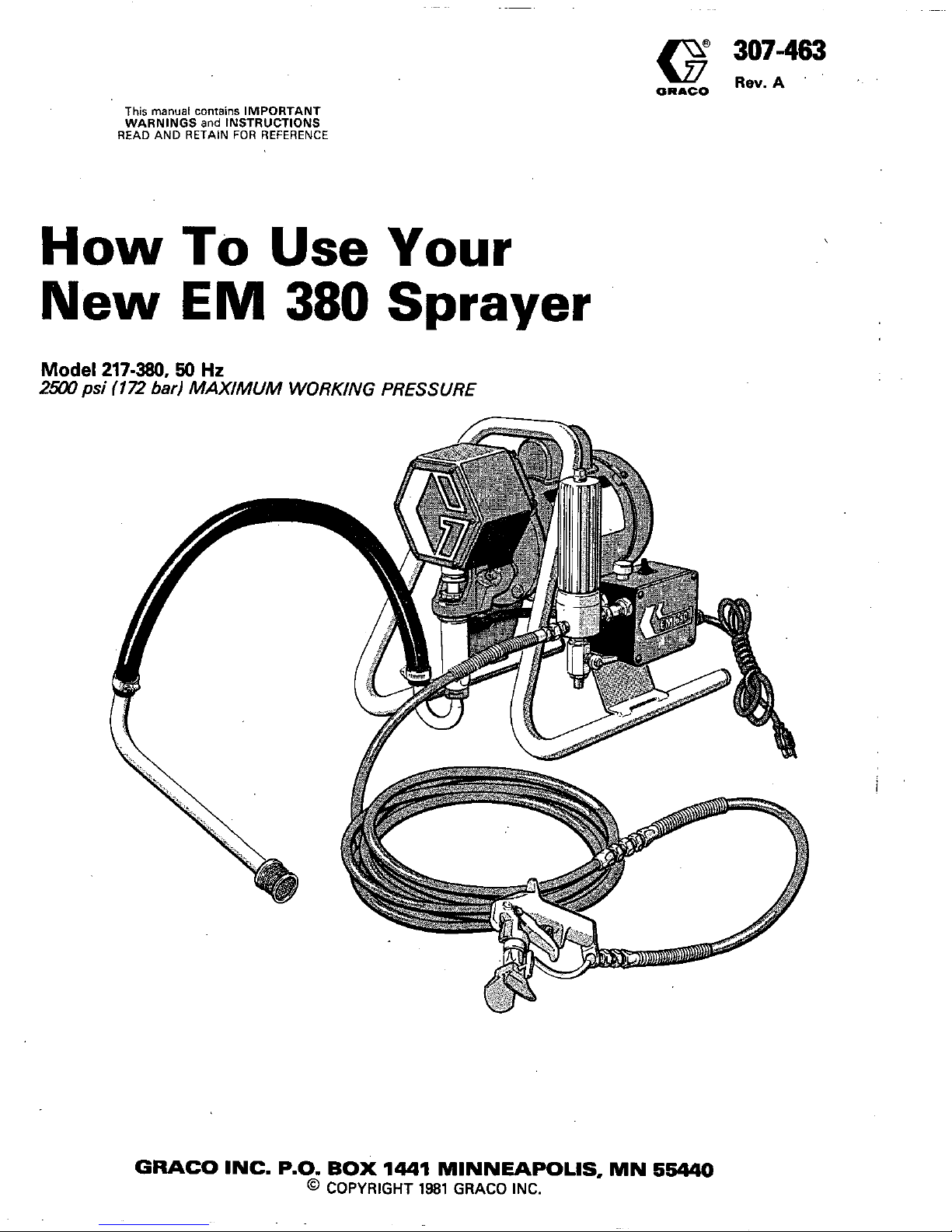
How
To
Use
Your
New
EM
380
Sprayer
256opsi
(172
bad
MAXIMUM WORKING PRESSURE
Model
217-380.50
Hz
GWCO INC. P.O.
BOX
1441
MINNEAPOLIS,
MN
55440
@
COPYRIGHT
1981
GRACO INC.
Page 2
HIGH
PRESSURE SPRAY CAN CAUSE SERIOUS INJURY.
FOR
PROFESSIONAL USE ONLY.
OBSERVE ALL WARNINGS.
Read and understand
all
instruction manuals before operating equipment.
INJECTION HAZARD
penetrate the skin and
cause
extremely serious injury,
Fluids under high pressure from spray or leaks can
including the need for amputation.
NN€R
point the spray gun
at
anyone or any pan of the
body.
NNER
put hand or fingers over the spray tip.
NNER
try
to stop or deflect leaks with your hand or
body.
SPRAY GUN SAFETY
When spray gun is not actually spraying, always set the
gun safety latch in the closed or "SAFE" position, making the trigger inoperative.
DO NOT REMOVE
OR
MODIFY
any part of the gun.
Check diffuser operation by using the
lowest
possible
spray pressure with spray tip removed. Trigger gun and
maintain firm metal to metal contact between gun and
metal waste container. Fluid emitted should be diffused
into an irregular stream.
ALWAYS
have the tip guard in place when spraying.
CHECK OPERATION
OF
ALL GUN SAFETY
DEVICES BEFORE EACH USE.
MEDICAL TREATMENT
Always remove the
tip
from the gun
to
clean
it.
If any fluid appears to penetrate your skin, get
EMERGENCY MEDICAL CARE AT ONCE.
from gun. A plugged line contains fluid under pressure.
Be
very careful when removing the
spray
tip
or hose
Tell the doctor exactlv what fluid was iniected. For
DO NOT TREAT AS A SIMPLE CUT.
loosen
tir,
guard or hose couDling slight&
and relieve the
If
tip or line is plugged, open the drain valve,
then
treatment instructions have your doctor
Cali
the
NATIONAL POISON CENTER NETWORK
pressure slowly before removing completely.
"
SYSTEM PRESSURE
This unit develops
2500
psi
(172
bar) fluid pressure at unit. Before each
use,
check
entire
hose for cuts, leaks,
ponents have
a
maximum working pressure rating
at
100
cycles per minute. Always be sure that
all
com- abrasion or bulging of cover or damage of movement of
couplings.
If
any of these conditions exist, replace the
least as high. hose immediately.
Never use tape or any device
to at-
NNER
leave a pressurized unit unattended.
tempt
to
mend the hose.
Do
not
use
chemicals or agents in the hose which are
DO
NOT ABUSE
HOSE
Improper use or handling
of
hose could
resuk
in hose failure and Dossible Dersonal
not compatible with nylon tube and urethane cover
of
the hose.
injury or propeny damage.
Handle and route hose carefully to avoid kinking, abra-
sion, cutting or exDosure to temDeratures above 180°F Tiahten
all
fluid connections securely before each
use.
'
'
NEVER ATTEMPT TO RECOUPLE THE HOSE1
(82OC)
or below
-4i)oF
(-4OOC).
Do
not
use
hose to pull
1
PREVENT STATIC SPARKING
Always be sure
all
equipment and objects being sprayed
are properly grounded. The high velocity flow of fluid
creates static electricity.
Sparks may cause fire or explosion.
Use
only conductive or grounded fluid hoses for airless
applications.
Be
sure that gun
is
grounded through hose
connections.
Once each week, check electrical resistance of hose
(when using multiple hose assemblies, check overall
resistance). Overall (end to end1 resistance of unpressurized hose must not exceed
29
megohms (max.)
for any coupled length or combination of hose lengths.
If hose exceeds these limits, replace
it
immediately,
2
307-463
Never exceed
500
ft
(150
m) overall combined hose
length.
Plug
into an outlet
at
least
20
ft
(6m) from the area
where
you
are spraying.
If
you
use
an extension cord,
it
must have 3 wires of
at
least
12
gauge
(2.5
mm2) and
should not be over
100
ft
(30.3
m) long.
When flushing equipment, remove spray tip, use the
lowest possible pressure, and maintain firm metal to
metal contact between gun and metal waste container.
This reduces the chance of static sparking.
Follow the coating and solvent manufacturer's safety
precautions and warnings.
Page 3
KEEP CLEAR
OF
MOVING PARTS USE
EXTREME
CARE
WHEN
SERVICING
The electric motor has an overheating protection device Before removing any part for cleaning or servicing,
which automatically restarts the motor when
it
cools. always disconnect power source and carefully relieve
stopped, shut
off
the unit, relieve pressure and pull out safety and any other equipment safety locks, and open-
So,
before examining or working on a motor which has fluid pressure
by
triggering spray gun, engaging trigger
the electrical
plug.
This
will
avoid the hazard of the ing any drain or bleeder valves. Leave drain valve open
motor starting unexpectedly. during servicing. Remove tip from gun for cleaning.
not put your fingers into any openings in shield.
KEEP
CLEAR
of moving parts when unit is running; do
ALWAYS CHECK
to be sure switch is
OFF
and
all
lines
are clear
of
moving parts before plugging in the power
cord.
ALWAYS
unplug unit before removing gearbox cover
for any reason.
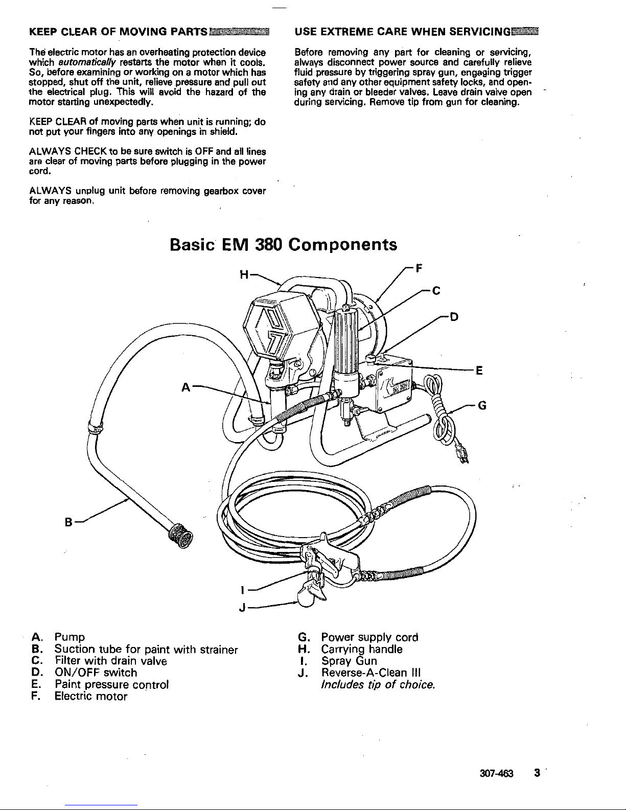
Basic'
EM
380
Components
E
G
B
A.
Pump
B.
Suction tube for paint with strainer
G.
Power supply cord
C.
Filter
with
drain valve
H.
Carrying handle
1.
Spray Gun
D.
ON/OFF
switch
J.
Reverse-A-Clean
111
E.
Paint pressure control
F.
Electric motor
307463
3
Page 4

Preparation For Use
PACKING
NUT/
Connect Hose and Gun
screw the 50 ft (15
m)
fluid hose into the
1/4
Remove the plastic cap plug from the filter and
end hose between the fluid hose and the gun's
npsmlf) filter outlet. Then connect the whip
inlet connection. Don't
use
thread sealant,
and don't install the spray tip yet!
CAUTION
Always
use
at
least 50
ft
(15
m)
of fluid
hose. Never use metal braid hose.
Fill Packing NutANet Cup
Pour Graco Throat Seal Liquid (TSL), supplied
with
the sprayer,
into
the packing nut/wet cup
until it's 1/3 full. Keep the wet cup full to help
throat packings.
protect and prolong the life of the pump's
Check Electrical Service and Plug In
Before plugging in the sprayer, be sure the
This unit has no plug because
of
varying elec-
electrical service is
220
V,
50 HzAC, 15 AMP.
trical codes in various parts of the world. Have
a
licensed electrician install a plug conforming
to local code.
With
the
ON-OFF switch in the
a grounded outlet.
OFF
position, plug the power supply cord into
Set Pressure Control
Turn the pressure control knob to the lowest
setting.
Flushing Pump
An important part of the care and
maintenance of your
EM
380
is proper
flushing. See "Flushing Guidelines" on page 5
for "When to Flush" and "How to Flush".
4
30743
Page 5

Flushing Guidelines
~~~~~~~~~~~~~~~~~~~~~~~~~~~~~~~~~
1.
New
unit.
Your new
EM
380
was factory
4.
Changing
from
Oil-Based to Water-
tested in
No.
10
motor oil and the oil was
Based Paint. Flush with mineral spirits,
left in
it
to protect the parts.
then soapy water, followed
by a clean
the oil with mineral spirits, then flush out
Before Using Water-Based Paint,
flush out water rinse.
the mineral spirits with soapy water follow-
ed by
a
clean water rinse.
5.
Storage
Before Using Oil-Based Paint,
flush out the mineral spirits and leave the pump, hose
Water-Based Paint:
flush with water, then
oil with mineral spirits only. and gun filled with mineral spirits.
Oil-Based Paint;
flush with mineral spirits
2.
Changing
colors.
Flush with a compatible and leave the pump, hose and gun filled
solvent such
as
mineral spirits or water. with mineral spirits.
3.
Changing from Water-Based
to
Oil-
6.
Startup After Storage.
Based Paint. Flush with soapy water,
Before Using Water-Based Paint,
flush out
then mineral spirits. the mineral spirits
with
soapy water follow-
ed
by
a clean water rinse.
When Using Oil-Based Paint,
flush out the
mineral spirits and the unit is ready to use.
5.
Check
all
paint line fittings for leaks.
If
any
2.
Remove the filter bowl and screen; clean drain valve slowly to relieve pressure, then
leak, first shut
off
the sprayer, open the
the
screen separately and install the bowl
without screen. Be sure the filter drain
tighten fittings. Start the sprayer again and
recheck the fittings.
valve
is
closed.
PEN
POSITION
6.
Remove the suction tube from the solvent
3.
Pour half a gallon
(2
liters) of compatible pail. Squeeze the trigger and let the pump
solvent (mineral spirits or water, see force the solvent out of the hose..But
don't
"When to Flush") into a bare metal pail.
Put the suction tube into the pail.
let the pump run dry
for
more than
1/2
minute!
Then turn
off
the sprayer and
engage trigger safety.
4.
Point the spray gun (with no
tip
installed)
into
a
metal waste container, and with a
7.
Unplug the power supply cord, put a can
metal part of the gun firmly touching the
metal container, squeeze the gun trigger.
under the drain valve, and slowly open the
Now turn the sprayer's ON-OFF switch to
valve to relieve pressure. Unscrew the filter
ON and turn the pressure control knob
bowl and reinstall the clean screen.
toward INCREASE
until
the motor starts.
Reinstall the bowl, hand tight only.
Keep the gun triggered until clean solvent
8.
If
you have flushed with mineral spirits and
comes from the nozzle. The pump
will
stop
after you release the trigger. Engage trigger
are going to use a water-based material,
flush
with
soapy water, followed by clean
and static markina.
safety. This procedure avoids splashing water rinse. Repeat Step
1.
"-.
"
c
Page 6

Preparing the Paint
Prepare the paint as instructed by the New paint seldom needs thinning. Add solvent
manufacturer.
If
the paint has been opened to old and remixed paints to replace the
sol-
before, remove any skin that has formed. Stir
the paint thoroughly to dissolve hard
vent lost through evaporation.
Do
not add too
much solvent
as
thin paint
is
hard to control
pigments. Strain the paint through
a
fine nylon and doesn't cover very
well.
Follow the paint
mesh bag (available at most paint dealers) to manufacturer's recommendations on thinning.
the spray tip. This is probably the most impor-
remove particles that might clog the filter or
tant step toward trouble-free spray painting.
Priming the Sprayer
Plug the sprayer into a grounded 3-prong tion tube into the pail of paint, but don't install
outlet. Close the drain valve. Put the paint suc- the spray tip yet. Disengage the trigger safety,
aim the gun into a metal waste container,
so
a
container, squeeze the gun trigger, turn on the
metal part of the gun is touching the metal
sprayer and let
it
run until
all
air is forced out
of
the system.
NOTE:
If
the pump is hard to prime, place
a
container under the drain valve, turn
on the sprayer and open the drain
valve. Let the sprayer run until paint
is
drain valve. This method bleeds the air
coming from the drain valve.
Close
the
from the pump. Then release the trig-
ger safety and trigger the gun to prime
the hose. Engage the trigger safety.
Install
Tip
and
Tip
Guard.
the trigger safety,
and
slowly open the drain
Unplug the sprayer, trigger the gun, engage valve. Unscrew the retaining nut from the gun.
Install the Reverse-A-Clean
111
spray housing
with tip installed
(see
instruction manual
.
307-321). Then, tighten the retaining nut by
tighten the retaining nut
1/4
turn. This is
hand until snug. Finally, use
a
wrench and
essential to prevent leaking.
Page 7

Adjusting the Spray Pattern
Adjust the pressure control knob
so
the
fluid
Now test the spray pattern on a piece of light
pressure completely atomizes the spray from
the gun. Always use the lowest possible
colored paper. The tip position determines the
direction of the pattern width.
To
adjust the
pressure to get the desired results.
the retaining nut to position the tip
so
the'
'
pattern, engage the trigger safety and loosen
groove is horizontal for
a
horizontal pattern or
vertical for
a
vertical pattern. Once positioned,
tighten the retaining nut.
SPOTTY
GOOD
INCREASE PATTERN
PAlTERN
FULL
PRESSURE
the day's operation. First unplug the sprayer,
Clean the front
of
the tip out frequently during
drain valve to relieve system pressure. Then
engage the trigger safety, and open the filter
from building up and clogging the tip.
use
a
solvent soaked brush to keep material
Cleaning a Clogged Tip
release the trigger, engage the trigger safety,
If the spray tip clogs while spraying, simply
and rotate the Reverse-A-Clean handle
180".
Disengage the trigger safety and trigger the
'gun into
a
waste container. This
will
remove
most obstructions. Return the handle to the
original position and resume spraying.
If
fluid pressure
fails
to clear the spray tip, shut
off
the sprayer and unplug
it.
Open the drain
valve
to
relieve system pressure. Disassemble
in reverse order of the assembly instructions.
(See
manual
307-321).
Thoroughly
clean
all
for wear or damage. Replace parts as needed
parts in a compatible solvent. Inspect
all
parts
and reassemble.
WARNING
DO NOT hold your hand, body or a rag in
front of the spray tip when cleaning or
checking
a
clogged tip. Always point the
gun toward the ground or into a waste
container when checking to see if the
obstruction has cleared.,
DO
NOT try to "blow back" paint; this is
NOT an
air
spray unit.
307-463
7
Page 8

Best Application Methods
RIGHT
Always hold the gun perpendicular to the surface and keep the gun at an even
12
to
14
in.
(300-356
mm)
from the surface you are
spraying.
I
WRONG
I
Begin moving the
gun
in a horizontal direction
at a steady rate. Start the spray stroke
off
the
moving.
Then, while the gun- is still moving,
target surface and pull the trigger
as the gun
is
and as you approach the other edge, release
the trigger. This method avoids excess paint
build-up at the end of each. stroke.
The correct speed for moving the gun will
allow a full, wet coating to
be
applied without
runs or sags. Lapping each stroke about
50%
over the previous stroke produces uniform
paint thickness. And spraying
in
a uniform pattern alternately from right to left, then left to
right, provides a professional finish.
The best way to control the rate
of
coverage
is
with the gun
tip
size.
A
small
tip
orifice applies
orifice applies more paint and a wider pattern.
less
paint
and a narrower pattern. A larger
tip
Do
not try
to
increase coverage
by
increasing
the fluid pressure! Using the lowest pressure
prolong the life
of
your sprayer and minimize
paint lost by overspray.
necessary to get the results
you
want
will
help
8
307-463
Page 9

For interior corners, such
as
on a bookcase or
inside a cabinet, aim the gun toward the
center of the corner to spray.
By
dividing the
spray pattern this way, the edges on both
sides are sprayed evenly.
w-
However, you can make one from a thin,
should be
at
least
14
in.
(356
mml wide and
lightweight piece of sheet metal. The shield
have two parallel,
30"
angles, one above the
with
a
shield, hold
it
firmly against the surface
line and one below the line. When spraying
and angle the spray away from the edge of the
shield. This is to keep the spray
away
from the
hand holding the shield, and to prevent paint
from being forced underneath the edge and
onto the protected
area.
,.
..,
. ..
,
..
.
WARNING
When using a shield, be very careful to
A
shield held
by
the painter can be used in-
keep the spray away from the hand
holding the shield. Spray from the gun
at
stead of masking to protect areas not to be
painted. Specially designed shields are
this distance could penetrate the skin,
causing serious injury.
available
at
many professional paint stores.
-
If
there is a wind, angle the spray pattern into
the wind to minimize drifting. Paint from the
ground to the roof.
Shrubs. When painting next to the house, use
rope and stakes to tie the shrubs back from
with a canvas dropcloth as the painter ap-
the surface to be painted. Then cover them
dropcloth as
soon
as
the area is painted, to
proaches the area.
Remove
the canvas
prevent possible dama,ge to the shrubs.
Concrete walks.
If
the walkways
will
be walk-
ed on, cover them
with
a
canvas dropcloth to
avoid slipping. Otherwise a plastic cloth is
all
that is needed.
Electrical outlets and lamps. Protect electrical
outlets with masking tape. Cover lamps with
plastic bags secured with masking tape.
automobiles, picnic tables, lawn furniture, etc.
Nearby objects. Move objects such as
case of
a
nearby home, make a protective bar-
up-wind of the surface to be sprayed. In the
rier by hanging plastic between two long
poles.
307-463
9
Page 10

Shutdown And Care
Of
Your Sprayer
WARNING
Always shut
off
the pump and relieve
system pressure when you are done
spraying for a while, when storing the
sprayer, and before adjusting, removing
or adding any parts.
To relieve pressure, shut
off
the pump,
trigger the spray gun, engage the trigger
safety, and open the drain valve.
Check the packing nut/wet cup periodically.
The packing nut should be tight enough to
stop leakage -no tighter. Use
a
screwdriver
tighten! Overtightening may cause binding
and light hammer to adjust the nut. Don't over
and excessive packing wear.
Clean the outlet filter often and whenever the
sprayer is stored. On the last workday of the
week, flush all the paint out of the sprayer.
See
"Flushing Guidelines" on page
6.
If
you
are using
a
paint that will dry overnight, flush
the sprayer daily
at
shutdown.
For very short shutoff periods leave the suc-
tion tube in the paint and clean the spray tip.
Always wrap the hose around the sprayer
when storing
it,
even
if
only overnight, to help
'
'
protect the hose from damage.
for overnight storage, you should fill the
Don't store the sprayer with water in
it.
Even
sprayer with mineral spirits. This prevents rust
and greatly extends the life of the sprayer.
. .
..
..
..
10
307-463
Page 11

Troubleshooting
Guide
WARNING
Always
disconnect the sprayer from the
power
source
and
relieve system pressure
before attempting any service.
PROBLEM
Electric motor won't run
Electric motor stops while spraying
Electric motor runs, but
no
output
Electric motor labors when starting
blows fuses
F
-
-
-
-
-
-
-
-
-
'The electric motor has an overhea
opens, unplug power cord and
let
overheating. Always
use
the lowe:
Excessive surge
at
spray gun
Not enough paint pressure
Tails or fingers in spray pattern
Paint runs or sags
Static sparking from spray gun
CAU.SE
wit
fuse blown
Power cord unplugged, or building cir-
Overload switch has opened
Pressure setting
too
low
cuit fuse blown
Power cord unplugged, or building cir-
Overload switch has opened
Pressure setting too low
Tip or filter plugged
Displacement pump frozen or gear trail
damage
Capacitor failure
Tip or.filter plugged
Spray tip too big
or
worn
Paint too viscous
Wrong type hose
Pressure setting too low
Spray tip too big or worn
Pressure setting too low
Outlet filter dirty or plugged
Spray tip
too
big or worn
Paint supply low or pail empty
Paint too viscous
Wrong type hose
i
Outlet filter dirty or plugged
Sprayer sucking air or gun needle not
seating
Sprayer or work not grounded
SOLUTION
Check, replace
decrease pressure
Unplug power cord*,
Increase
Check, replace
Unplug power cord*,
cool
relieve pressure-allow to
Increase
Remove and clean
Thaw"'
Replace capacitor
Remove and clean
Change tip
-
see manua'
307-321
Thin
Use
minimum
50
ft
115
m)
static
free nylon
hose only -wire braid
hose unacceptable
Increase
Change tip
-
see
manual
307-321
Increase
Clean
Change tip
-
see
manual
307-321
Fill
Thin
Use
minimum
~50
h
I15
m) static free nylon
hose
only - wire braid
hose
unacceptable
Clean-see manual
Tighten fittings, service
gun-see manual 307-046
Check, ground
307-273
J
protector switch which automatically resets on cooling. If
it
rayer cool for
30
to
60
minutes.
Also
try to correct the cause of
lressure setting needed.
**Freezing results from failure to replace flushing water with mineral spirits solvent.
Page 12

TECHNICAL DATA
Electric motor
Electric cord
Paint filter
Paint Pump
Wetted parts
Operating weight
0.5 hp (0.37285 kW), 1425 rpm,
220
V,
50
HzAC, single
phase with automatic reset thermal overload switch.
UL
recognized
No. 14 gauge, 3-wire; use 14 ga (min) 3-wire extension cord.
60
mesh
(250
micron) stainless steel screen with 3/8 nptlf)
inlet and 1/4 npt(f) outlets; reusable type.
2500
psi (172 bar) maximum working pressure;
0.33
gpm
(1.25 liter/min)output.
Delrin, Leather, Stainless Steel, Polyethylene,
Tungsten Carbide, Polyurethane, Nylon, Aluminum,
Nitralloy.
68
Ib (30 kg) approximately
Noise level
:
Does not exceed
3
ft
(914 mm) from machine.
Electrical requirements
:
220
V,
15 amp circuit
THE GRACO WARRANTY
Gram Inc. warrants
all
equipment manufactured by
it
and bearing
its
name to
be
free from defects in
material and workmanship under normal use and service. This warranty extends to the original purchaser
for a period of
12
months from the date of purchase and applies only when the equipment is installed and
operated in accordance with written factory recommendations. This warranty does not cover damage or
wear which, in the reasonable judgment of Graco. arises from misuse, abrasion, corrosion, negligence.
accident, substitution of non-Graco parts, faulty installation
or
tampering.
This warranty is conditioned upon the prepaid return of the equipment claimed to be defective for
examination by Graco to verify the claimed defect. If the claimed defect is verified, Graco will repair or
transportation prepaid. If inspection of the equipment does not disclose any defect in workmanship or
replace free of charge. any defective parts. The equipment will be returned to the original purchaser
material, repairs will be made
at
a reasonable charge and return transportation will
be
charged.
THIS LIMITED WARRANTY
IS
EXCLUSIVE, AND
IS
IN LIEU OF ANY OTHER WARRANTiES
(EXPRESS
OR
IMPLIED1 INCLUDING WARRANTY
OF
MERCHANTABILITY
OR
WARRANTY OF
FITNESS FOR A PARTICULAR PURPOSE AND
OF
ANY NON-CONTRACTUAL LIABILITIES
INCLUDING PRODUCT LIABILITIES BASED ON NEGLIGENCE
OR
STRICT LIABILITY. EVERY FORM
OF LIABILITY FOR DIRECT, SPECIAL
OR
CONSEOUENTIAL DAMAGES
OR
LOSS
IS
EXPRESSLY
EXCLUDED AND DENIED.
by Graco that are not manufactured
by
Graco (such as electric motors, switches, hose, etc.1 are subject
EQUIPMENT N.OT COVERED BY GRACO WARRANTY. Accessories or components of equipment sold
to the warranty.
if
any, of their manufacturer. Gram will provide purchaser with reasonable assistance in
making such claims.
Subsidiary and
Affiliate
Companies:
Canada: England; Switzerland; France; Germany; Hong Kong; Japan
Factory
Branches:
Atlanta. Dallas, Detroit,
Los
Angeles.
West
Caldwell
(N.J.1
GRACO
INC.
P.O.
BOX
1441
MINNEAPOLIS, MN
55440
PRINTED
IN
U.S.A.
Jn-463241
PTFEPTFEPTFE
 Loading...