

Page 1
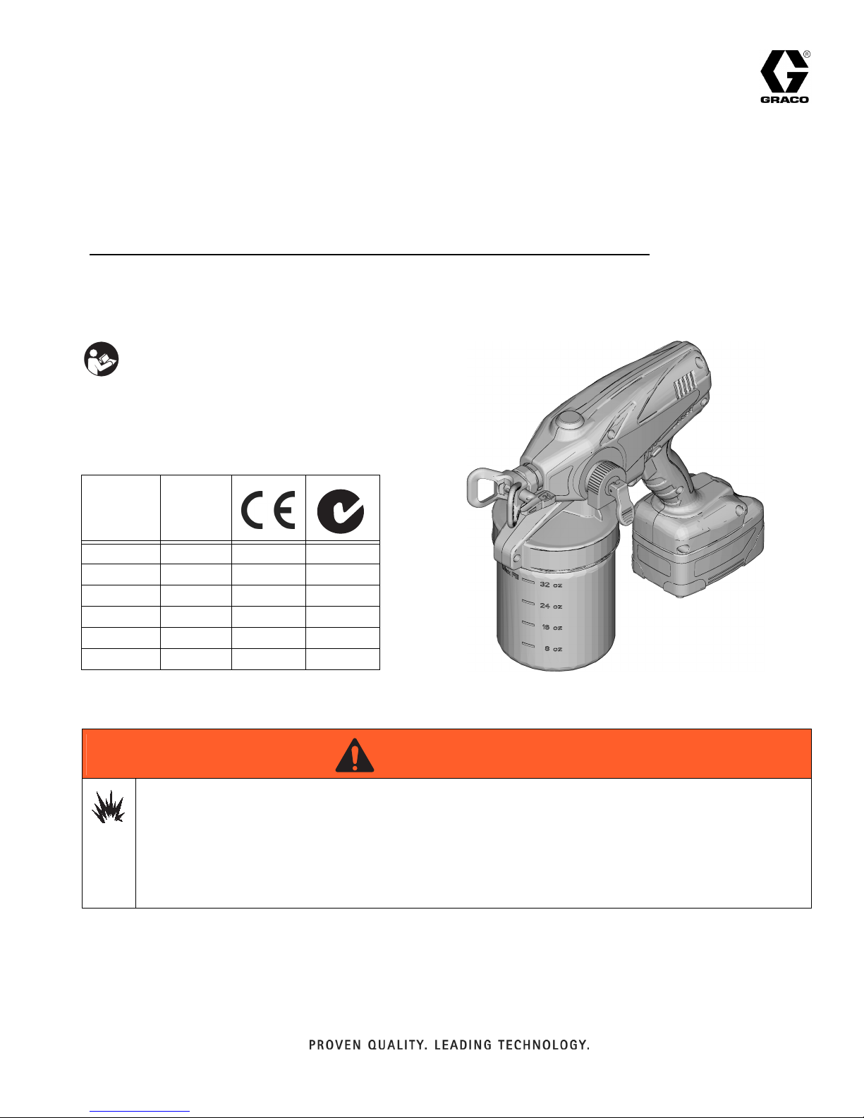
Operation - Repair - Parts
Cordless Hand-Held Paint Sprayers
- For portable spray applications of architectural paints and coatings only -
- Not approved for use in explosive atmosphere locations -
IMPORTANT SAFETY INSTRUCTIONS
Read all warnings and instructions in this
manual. Save these instructions.
All Models:
Maximum Working Pressure 2000 psi (14 MPa, 138 bar)
Model
16N664 230V ✓
16N665 110V ✓
16N666 230V ✓
16N668 100V ✓
16N669 230V ✓
16N670 230V ✓
Charger
Volt a ge
3A2853A
EN
ti19605a
Use only water-based materials. Do not use materials which state “FLAMMABLE” on the packaging. For
more information about your material, request MSDS from distributor or retailer.
Spraying certain materials may cause static build-up in the sprayer that can result in static shock to
the user. If this occurs, first ensure the material has a flash point greater than 100° F (38° C) and does not
state that it is FLAMMABLE anywhere on the package. If still feeling a static shock, the material likely contains a non-mineral spirits fluid such as, but not limited to, xylene, toluene, or naphtha, which can build up
static. Switch to an alternative material.
WARNING
WARNINGWARNINGWARNING
Page 2

Table of Contents
Table of Contents
Warnings . . . . . . . . . . . . . . . . . . . . . . . . . . . . . . . . . . . . . . 3
Component Identification . . . . . . . . . . . . . . . . . . . . . . . . . 5
Charging the Battery . . . . . . . . . . . . . . . . . . . . . . . . . . . . . 6
Charger Status Indicator Lights . . . . . . . . . . . . . . . . . . 6
Sprayer Status Indicator Light . . . . . . . . . . . . . . . . . . . 6
Common Procedures . . . . . . . . . . . . . . . . . . . . . . . . . . . . 7
Trigger Lock . . . . . . . . . . . . . . . . . . . . . . . . . . . . . . . . . 7
Prime/Spray Valve . . . . . . . . . . . . . . . . . . . . . . . . . . . . 7
Pressure Relief Procedure . . . . . . . . . . . . . . . . . . . . . . 7
Reversible Spray Tip . . . . . . . . . . . . . . . . . . . . . . . . . . 8
Pressure Control Knob . . . . . . . . . . . . . . . . . . . . . . . . . 8
Flexible Suction Tube . . . . . . . . . . . . . . . . . . . . . . . . . . 8
Sprayer Setup . . . . . . . . . . . . . . . . . . . . . . . . . . . . . . . . . . 9
Starting a New Job
(or Refilling the Material Cup) . . . . . . . . . . . . . . . . . 10
Choosing the Correct Tip . . . . . . . . . . . . . . . . . . . . . . . . 11
Understanding Tip Number . . . . . . . . . . . . . . . . . . . . 11
Selecting Tip Hole Size . . . . . . . . . . . . . . . . . . . . . . . 11
Choosing Pressure Control Knob Setting . . . . . . . . . . 11
Install Spray Tip/Guard
Assembly (if not installed) . . . . . . . . . . . . . . . . . . . . 12
Getting Started with Basic Techniques . . . . . . . . . . . . . 12
Triggering Sprayer . . . . . . . . . . . . . . . . . . . . . . . . . . . 12
Aiming Sprayer . . . . . . . . . . . . . . . . . . . . . . . . . . . . . . 13
Spray Pattern Quality . . . . . . . . . . . . . . . . . . . . . . . . . 13
Unclogging Spray Tip/Guard Assembly . . . . . . . . . . . 13
Shutdown and Cleaning . . . . . . . . . . . . . . . . . . . . . . . . . 14
Flushing Sprayer . . . . . . . . . . . . . . . . . . . . . . . . . . . . 14
Cleaning Sprayer Exterior . . . . . . . . . . . . . . . . . . . . . 16
Storage . . . . . . . . . . . . . . . . . . . . . . . . . . . . . . . . . . . . . . . 16
Replacement Parts . . . . . . . . . . . . . . . . . . . . . . . . . . . . . 17
Inlet Valve Fitting Removal/Service . . . . . . . . . . . . . . . . 20
Outlet Valve Fitting Repair . . . . . . . . . . . . . . . . . . . . . . . 21
General Service . . . . . . . . . . . . . . . . . . . . . . . . . . . . . . . . 22
Wiring . . . . . . . . . . . . . . . . . . . . . . . . . . . . . . . . . . . . . 22
Pressure Control Knob . . . . . . . . . . . . . . . . . . . . . . . . 22
Troubleshooting . . . . . . . . . . . . . . . . . . . . . . . . . . . . . . . 23
Troubleshooting Leaks . . . . . . . . . . . . . . . . . . . . . . . . 27
Technical Data . . . . . . . . . . . . . . . . . . . . . . . . . . . . . . . . . 28
Preferred Material Settings Log . . . . . . . . . . . . . . . . . . . 29
Notes . . . . . . . . . . . . . . . . . . . . . . . . . . . . . . . . . . . . . . . . 30
Notes . . . . . . . . . . . . . . . . . . . . . . . . . . . . . . . . . . . . . . . . 31
Graco Standard Warranty . . . . . . . . . . . . . . . . . . . . . . . . 32
Important User Information
Before using your sprayer read this Operation manual for complete instructions on proper use and safety warnings.
DO NOT RETURN THIS SPRAYER TO THE STORE!
If you experience problems, contact Graco Product Support at www.graco.eu
Congratulations! You have purchased a high-quality sprayer made by Graco Inc. This sprayer is designed to provide superior
spray performance with water-based architectural paints and coatings. This user information is intended to help you
understand the types of materials that can be used with your sprayer.
Before using this equipment, be sure to read and follow the information on your container label and ask for a Material Safety
Data Sheet (MSDS) from your supplier. The container label and MSDS will explain the contents of the material and the
specific precautions related to it.
Paints, coatings and clean-up materials generally fit into one of the following 2 basic categories:
WATER-BASED: The container label should indicate that the material can be cleaned up with soap and water.
Your sprayer is compatible with this type of material. Your sprayer is NOT compatible with harsh cleaners such as
chlorine bleach.
FLAMMABLE: This type of material contains flammable solvents such as xylene, toluene, naphtha, MEK, lacquer
thinner, acetone, denatured alcohol, and turpentine. The container label should indicate that this material is FLAMMABLE. This type of material is NOT compatible with your sprayer and CANNOT be used.
2 3A2853A
Page 3
Warnings
Warnings
The following warnings are for the setup, use, maintenance, and repair of this equipment. The exclamation point symbol
alerts you to a general warning and the hazard symbols refer to procedure-specific risks. When these symbols appear in
the body of this manual or on warning labels, refer back to these Warnings. Product-specific hazard symbols and warnings
not covered in this section may appear throughout the body of this manual where applicable.
WARNING
WARNINGWARNINGWARNING
FIRE AND EXPLOSION HAZARD
Flammable fumes, such as solvent and paint fumes, in work area can ignite or explode. To help prevent fire and
explosion:
• Sprayer generates sparks. Do not spray or flush with flammable liquids.
• Use only water-based materials.
• Keep spray area well-ventilated. Keep a good supply of fresh air moving through the area.
• Do not spray or flush with combustible materials near an open flame or sources of ignition.
• Paint or solvent flowing through the equipment is able to result in static electricity. Static electricity creates a risk
of fire or explosion in the presence of paint or solvent fumes. Keep sprayer at least 10 in. (25 cm) away from
objects while spraying or flushing.
• Do not smoke in the spray area.
• Do not operate light switches, engines, or similar spark producing products in the spray area.
• Keep area clean and free of paint or solvent containers, rags, and other flammable materials.
• Know the contents of the paints and solvents being sprayed. Read all Material Safety Data Sheets (MSDS) and
container labels provided with the paints and solvents. Follow the paint and solvents manufacturer’s safety
instructions.
• Fire extinguisher equipment shall be present and working.
SKIN INJECTION HAZARD
High-pressure spray is able to inject toxins into the body and cause serious bodily injury. In the event that injection
occurs, get immediate surgical treatment.
• Do not aim the sprayer at, or spray any person or animal.
• Keep hands and other body parts away from the discharge. For example, do not try to stop leaks with any part of
the body.
• Always engage the trigger lock when not spraying. Verify the trigger lock is functioning properly.
• Always use the nozzle tip guard. Do not spray without nozzle tip guard in place.
• Use caution when cleaning and changing nozzle tips. In the case where the nozzle tip clogs while spraying, follow the Pressure Relief Procedure for turning off the unit and relieving the pressure before removing the nozzle
tip to clean.
• Do not leave the unit energized or under pressure while unattended. When the unit is not in use, turn off the unit
and follow the Pressure Relief Procedure for turning off the unit.
• Check parts for signs of damage. Replace any damaged parts.
• This system is capable of producing 2000 psi. Use replacement parts or accessories that are rated a minimum
of 2000 psi.
• Do not carry the tool with a finger on the trigger.
• Verify that all connections are secure before operating the unit.
• Know how to stop the unit and bleed pressure quickly. Be thoroughly familiar with the controls.
EQUIPMENT MISUSE HAZARD
Misuse can cause death or serious injury.
• Always wear appropriate gloves, eye protection, and a respirator or mask when painting.
• Do not operate or spray near children. Keep children away from equipment at all times.
• Do not overreach or stand on an unstable support. Keep effective footing and balance at all times.
• Stay alert and watch what you are doing.
• Do not operate the unit when fatigued or under the influence of drugs or alcohol.
• Use only in dry locations. Do not expose to water or rain.
• Use in well-lit areas.
3A2853A 3
Page 4
Warnings
WARNING
WARNINGWARNINGWARNING
BATTERY HAZARD
The battery may leak, explode, cause burns, or cause an explosion if mishandled. Contents of an open battery can
cause severe irritation and/or chemical burns. If on skin, wash with soap and water. If in eyes, flush with water for at
least 15 minutes and seek immediate medical attention.
• Replace battery only in a well-ventilated area and away from flammable or combustible materials; including
paints and solvents.
• When battery is not in use, keep it away from metal objects like keys, nails, screws or other metal objects that
can short circuit the battery terminals.
• Do not throw into fire.
• Charge only with Graco-approved charger as listed in this manual.
• Do not store at temperatures below 32° or above 113° F (0° to 45° C).
• Do not use at temperatures below 40° or above 90° F (4° to 32° C).
• Do not expose battery to water or rain.
• Do not disassemble, crush, or penetrate the battery.
• Do not charge a battery that is cracked or damaged.
• Follow local ordinances and/or regulations for disposal.
CHARGER ELECTRIC SHOCK, FIRE AND EXPLOSION HAZARD
Improper setup or usage can cause electric shock, fire, and explosion.
• Charge only in a well-ventilated area and away from flammable or combustible materials, including paints and
solvents.
• Do not charge on a combustible or flammable surface.
• Do not leave battery unattended while charging.
• Immediately unplug charger and remove battery when charger is complete.
• Charge only Graco batteries listed in this manual; other batteries may burst.
• Use only in dry locations. Do not expose to water or rain.
• Do not use a charger that is cracked or damaged.
• If the supply cord is damaged, replace the charger or cord, depending on model.
• Never force the battery into the charger.
• When operating a charger outdoors, always provide a dry location and use an extension cord suitable for outdoor use.
• Disconnect the charger from the outlet before cleaning.
• Ensure that the outside surface of the battery is clean and dry before plugging into the charger.
• Do not attempt to charge non-rechargeable batteries.
• Do not disassemble the charger. Take charger to authorized service center when service or repair is required.
PRESSURIZED ALUMINUM PARTS HAZARD
Use of fluids that are incompatible with aluminum in pressurized equipment can cause serious chemical reaction
and equipment rupture. Failure to follow this warning can result in death, serious injury, or property damage.
• Do not use 1,1,1-trichloroethane, methylene chloride, other halogenated hydrocarbon solvents or fluids
containing such solvents.
• Many other fluids may contain chemicals that can react with aluminum. Contact your material supplier for
compatibility.
MOVING PARTS HAZARD
Moving parts can pinch or amputate fingers and other body parts.
• Keep clear of moving parts.
• Do not operate equipment with protective guards or covers removed.
• Pressurized equipment can start without warning. Before checking, moving, or servicing equipment, follow the
Pressure Relief Procedure in this manual. Disconnect power.
TOXIC FLUID OR FUMES HAZARD
Toxic fluids or fumes can cause serious injury or death if splashed in the eyes or on skin, inhaled, or swallowed.
• Read MSDS’s to know the specific hazards of the fluids you are using.
• Store hazardous fluid in approved containers, and dispose of it according to applicable guidelines.
PERSONAL PROTECTIVE EQUIPMENT
Wear appropriate protective equipment when in the work area to help prevent serious injury, including eye injury,
hearing loss, inhalation of toxic fumes, and burns. This protective equipment includes but is not limited to:
• Protective eyewear, and hearing protection.
• Respirators, protective clothing, and gloves as recommended by the fluid and solvent manufacturer.
4 3A2853A
Page 5
Component Identification
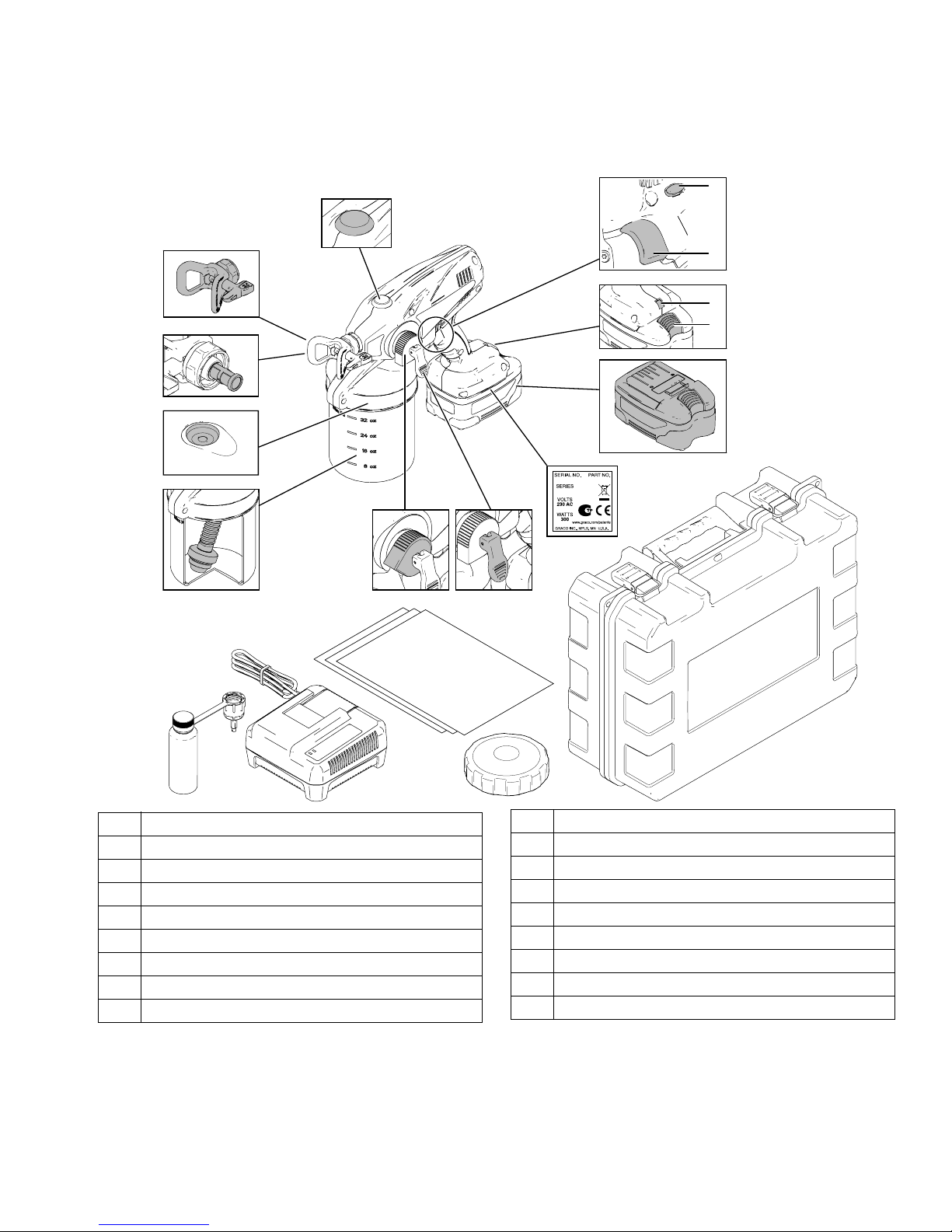
Component Identification
W
A
*B
C
T
S
R
P
N
L
D
G
E
F
A Spray Tip/Guard Assembly
*B Spray Tip Filter (Reverse Threaded)
CAir Vent Valve
D Flexible Suction Tube
E Pump Armor Storage/Startup Tool
F Battery Charger
G Pressure Control Knob
H Material Cup Liners (5 included)
JPrime/Spray Valve
J
H
ti18877a
M
K
K Material Cup Cover and Seal
L Part Number = Model Number
M Sprayer Case
NBattery
P Battery Release Button
R Sprayer Status Indicator Light
S Trigger
T Trigger Lock
W Outlet Valve Fitting Access Plug
*NOTE: Spray Tip filter is reverse-threaded. Turn left (or counter-clockwise) to tighten, turn right (or clockwise) to
loosen.
3A2853A 5
Page 6

Charging the Battery
Replace and charge battery only in a well-ventilated area and
away from flammable or combustible materials, including
paints and solvents.
Batteries are initially 50% charged to provide optimum battery
life and require charging before first use. It takes approximately 45 minutes to charge a dead battery to 80%, at which
point it can be used. It will take approximately 75 minutes to
fully charge a dead battery.
1. Place charger in a dry, well-ventilated area and away from
flammable or combustible materials, including paints and
solvents.
Charging the Battery
2. Plug charger into an electrical outlet and slide battery into
charger as shown (light will turn on in 5 seconds).
ti14990a
ti19607a
3. When battery becomes fully charged, immediately unplug
the charger from the power supply and remove the battery
from the charger.
NOTE: The amount sprayed with each battery varies depending on material, spray tip size, battery charge, and battery temperature. One battery fully charged will spray up to one gallon.
Amount sprayed will be less depending on spray tip size,
material sprayed, life of battery, temperature, and other environmental factors.
Charger Status Indicator Lights
NOTE: When the charger is plugged in, the charger status indicator lights will alternate between green and red several times
before they turn off, indicating that the charger is ready to charge a battery.
Label Appearance Description
Solid green light Indicates a full charge. Battery can be used.
Flashing green light
Flashing red light
Solid red light
Battery is charging, indicates 80% charge.
Battery can be used.
Battery is charging, indicates less than 80% charge.
Do NOT use battery.
Battery is too hot or too cold to charge. Remove battery and allow to cool or
warm up before charging.
Sprayer Status Indicator Light
Light* Appearance Description
ti18884a
No light Normal operation.
Solid red Battery is low on power and needs to be charged, or battery is too cold and
must warm up before spraying.
Flashing red Battery temperature is too high, or spray tip is clogged.
See Troubleshooting, page 23.
*NOTE: The sprayer status indicator light is only visible when sprayer trigger is engaged. You must squeeze and hold the trigger
to see the sprayer status indicator.
6 3A2853A
Page 7
Common Procedures
Common Procedures
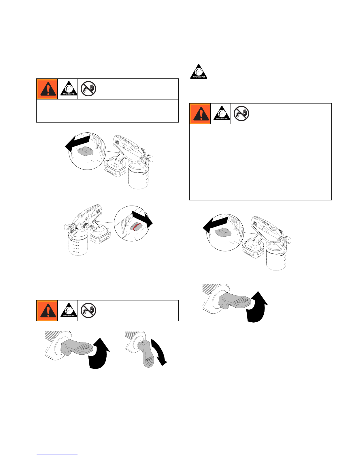
Trigger Lock
Always engage the trigger lock when you stop spraying
to prevent the sprayer from being triggered accidentally
by hand, or if dropped or bumped.
ti14995a
ti18866a
Trigger Locked
Follow the Pressure Relief Procedure
whenever you see this symbol.
Pressure Relief Procedure
Do not operate or spray near children. Do not aim the
sprayer at, or spray any person or animal. Keep hands
and other body parts away from the discharge. For
example, do not try to stop the paint flow with any part
of the body.
This sprayer builds up an internal pressure of 2000 psi
(14 MPa, 138 bar) during use. Follow this Pressure
Relief Procedure whenever you stop spraying and
before cleaning, checking, servicing, or transporting
equipment to prevent serious injury.
1. Engage trigger lock.
ti18874a
Trigger Unlocked
(red ring is visible)
Prime/Spray Valve
ti16700a
ti14999a
(For priming and releasing
UP position
pump pressure)
ti16701a
DOWN position
(Ready to spray)
ti18866a
ti14994a
2. Put prime/spray valve UP to release pressure.
ti14999a
ti16700a
3A2853A 7
Page 8
Common Procedures
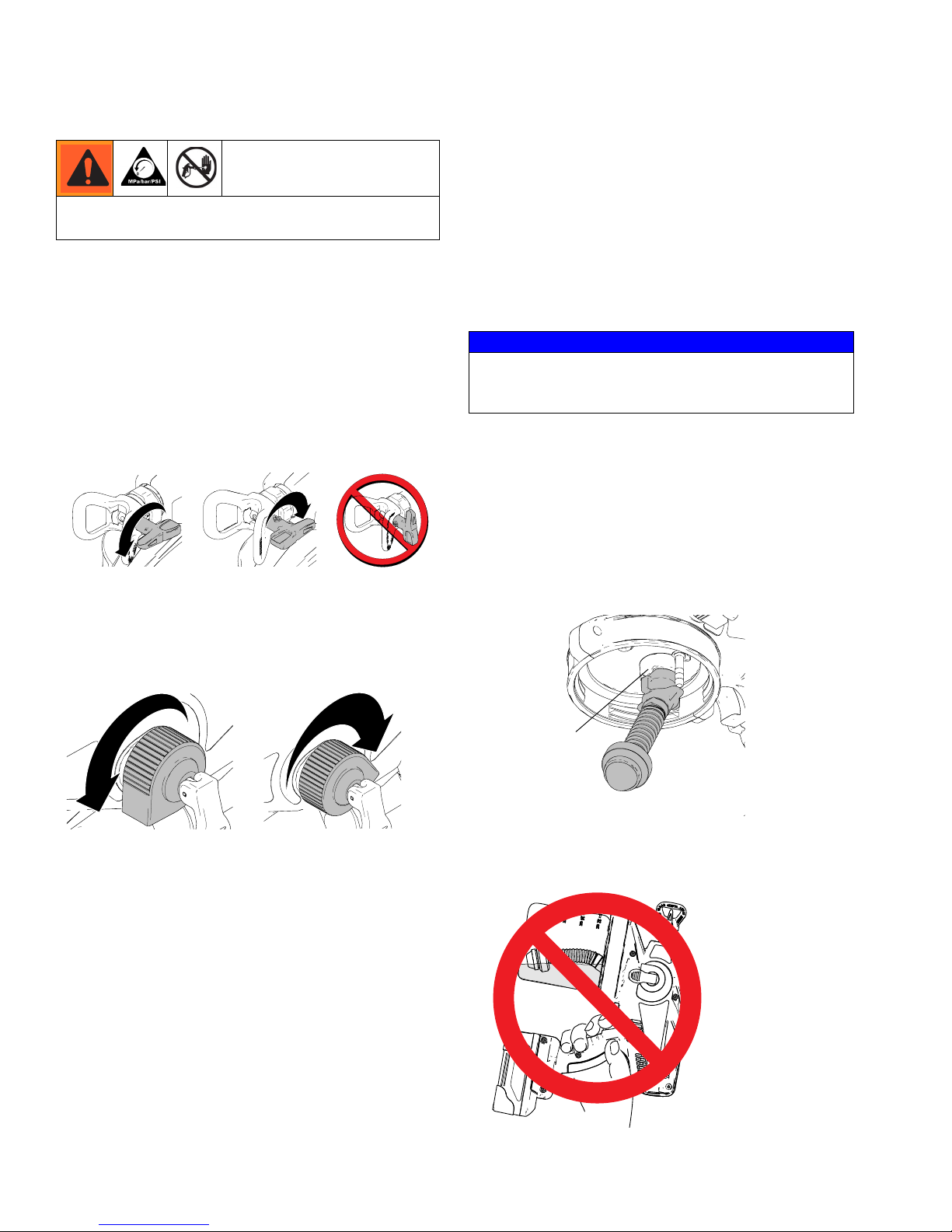
Reversible Spray Tip
Always perform Pressure Relief Procedure before
adjusting spray tip position.
In the event that particles or debris clog the spray tip,
this sprayer is designed with a reversible spray tip that
can be used to quickly and easily clear the particles and
resume spraying as quickly as possible.
• Always point the reversible spray tip
forward when spraying.
• When particles or debris get caught in the tip, it can
be reversed to quickly clean the tip.
•See Unclogging Spray/Tip Guard Assembly
(page 13) for detailed instructions.
ti16992a
ti14985a
Spray Tip Forward
(SPRAY position)
ti14991a
ti14991a
Spray Tip Reversed
(UNCLOG position)
ti15510a
ti15510a
• Thin materials sprayed at high pressure settings
may cause the sprayer to enter an operational mode
designed to protect it from overheating. This mode
is noticeable by the sprayer sounding like it is slowing down and will result in a poor spray pattern.
To exit this mode, turn pressure control knob
down to lowest pressure setting that results in
an acceptable spray pattern.
• If spraying in low pressure range, there may not be
enough pressure to clear the plug. Turn pressure
control knob up to clear the plug.
NOTICE
See Choosing Pressure Control Knob Setting on
page 11 for recommendations on the setting for your
job.
Flexible Suction Tube
This sprayer comes with a flexible suction tube for
multi-directional spraying without adjustment.
To ensure proper function of flexible suction tube, orient
as shown. Make sure tab from sprayer is aligned with
groove from flexible suction tube and firmly push into
place.
Pressure Control Knob
ti16705a
Minimum Pressure Setting
• To reduce overspray, always spray at lowest pressure that results in an acceptable spray pattern.
• Spray test pattern and adjust pressure to get
desired coverage.
• With some materials, if pressure is set too low, no
material may spray out. Turn pressure control knob
up.
ti16704a
Maximum Pressure Setting
Ta b
ti18881a
NOTE: If the sprayer is angled or tilted too far, the flexible suction tube will lose contact with the material and
the sprayer will stop spraying.
8 3A2853A
ti18878a
Page 9
Sprayer Setup
Sprayer Setup
Use only water-based materials. Do not use materi-
als which state “FLAMMABLE” on the packaging. For
more information about your material, request MSDS
from distributor or retailer.
Spraying certain materials may cause static
build-up in the sprayer that can result in static
shock to the user. If this occurs, first ensure the mate-
rial has a flash point greater than 100° F (38° C) and
does not state that it is FLAMMABLE anywhere on the
package. If still feeling a static shock, the material likely
contains a non-mineral spirits fluid such as, but not limited to, xylene, toluene, or naphtha, which can build up
static. Switch to an alternative material.
Keep spray area well-ventilated. Keep a good supply
of fresh air moving through the area.
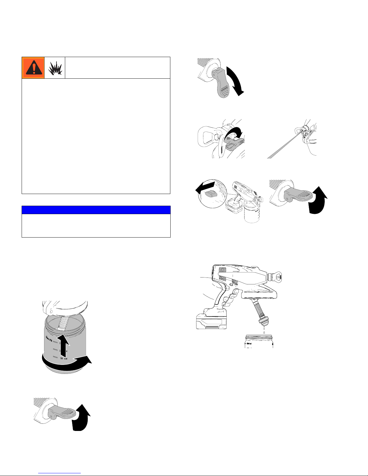
3. Put prime/spray valve DOWN to spray position.
ti16701a
ti15425a
4. Reverse Spray Tip to UNCLOG position and trigger
sprayer into a waste area for 10 seconds.
ti14991a
ti16713a
5. Engage trigger lock and put prime/spray valve UP to
release pressure.
NOTICE
Your sprayer is NOT compatible with harsh cleaners
such as chlorine bleach. Using these cleaners will
cause damage to the sprayer.
This sprayer arrives from the factory with a small
amount of test material in the system. It is important
that you flush this material from the sprayer before
using it for the first time:
1. Fill material cup with water or compatible solvent,
thread onto sprayer and hand tighten.
ti18871a
2. Put prime/spray valve to UP position, then hold trigger in for 10 seconds.
ti18866a
ti14994a
ti14999a
ti16700a
6. Unscrew and remove material cup.
7. Disengage trigger lock, hold sprayer slightly above
material cup, and pull trigger to discharge fluid from
pump.
ti18861a
8. Discard material in cup.
ti16700a
3A2853A 9
ti14999a
Page 10
Starting a New Job
(or Refilling the Material Cup)
Starting a New Job (or Refilling the Material Cup)
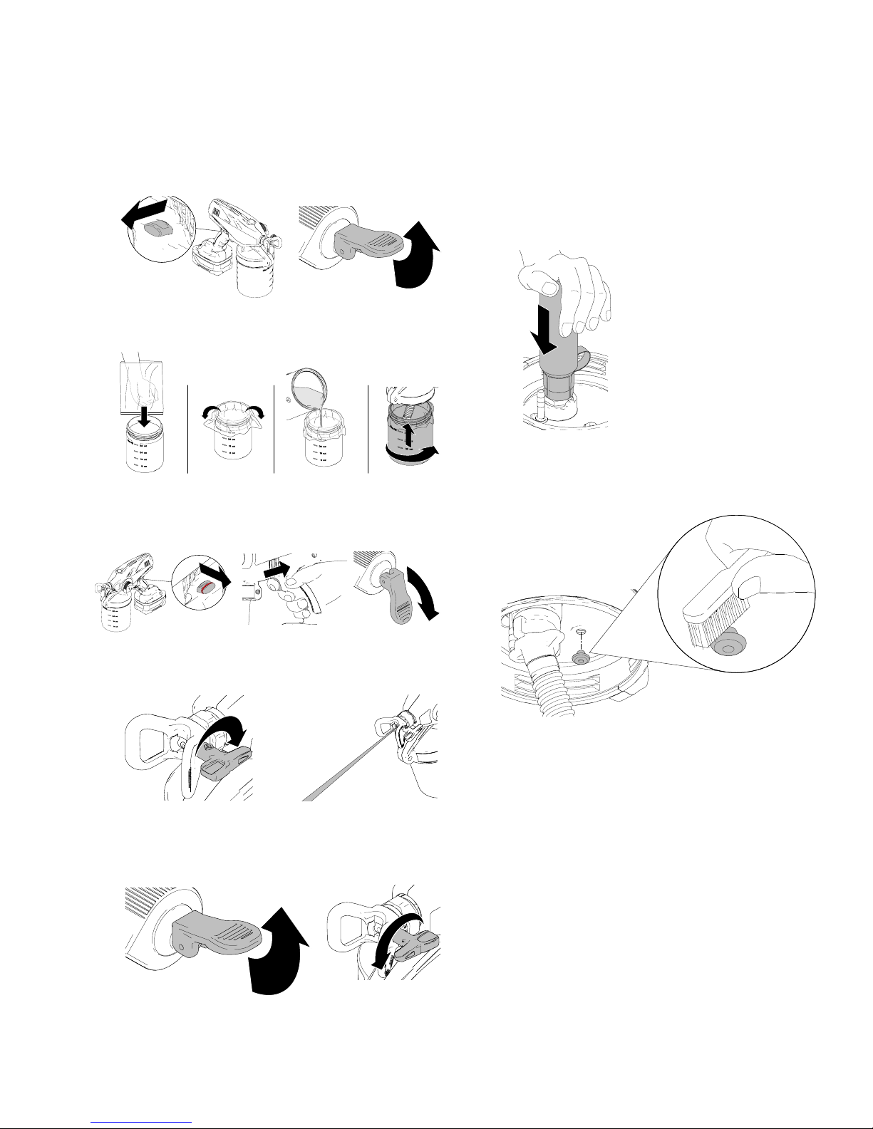
1. Engage trigger lock and put prime/spray valve UP to
release pressure.
ti18866a
ti14994a
ti16700a
ti14999a
2. Install material cup liner, fill with material, and
thread onto sprayer.
ti15474a
ti18868a
3. To fill sprayer with fluid, disengage trigger lock and
trigger sprayer for 10 seconds. Then release trigger
and put prime/spray valve DOWN to spray position.
If sprayer fails to prime, try one of the steps
below:
1. Use the Pump Armor storage/startup tool to clean
the inlet valve fitting. See Storage, page 16.
2. Clean air vent holes or the air vent valve,
depending on model. See Shutdown and Clean-
ing, page 14. Remove air vent valve, clean, and
reinstall.
ti18874a
ti14995a
ti15418a
ti16716a
ti15425a
ti16701a
4. Reverse spray tip to UNCLOG position, pull trigger
and release.
ti14991a
ti14991a
ti14985a
ti16713a
5. Put prime/spray valve UP to release pressure. Then
rotate spray tip back to spray position.
NOTE: Failure to perform this operation could result
in poor spray pattern.
ti16700a
ti16992a
ti18876a
10 3A2853A
Page 11
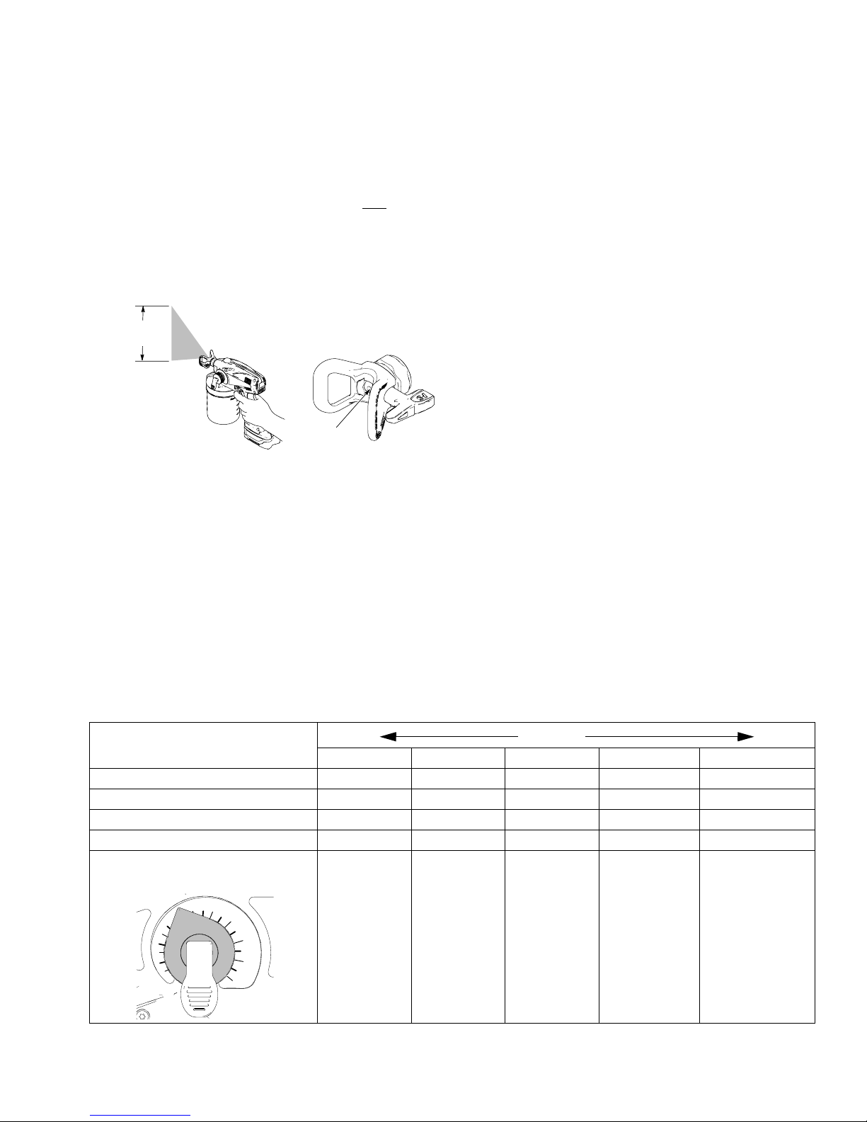
Choosing the Correct Tip
Choosing the Correct Tip
Understanding Tip Number
The last three digits of tip number (i.e.: XXX517) contains information about hole size and fan width on surface when gun is held 12 in. (30.5 cm) from surface
being sprayed.
First digit when doubled = approximate fan width
517 tip has
10 - 12 in.
fan width
517 tip has
a 0.017 in.
hole size
Last two digits = tip hole size in thousands of an inch
Example: For a 10-12 in. (254-305 mm) fan width and a
0.017 in (0.43 mm) hole size, order part number
PST517, depending on your sprayer model number.
ti19498a
Selecting Tip Hole Size
• Tips come in a variety of hole sizes for spraying a
range of fluids. The sprayer includes a 0.017 in.
(0.43 mm) tip for use in most spraying applications.
Use the table below to determine the range of recommended tip hole sizes for each fluid type.
• Consider coating and surface to be sprayed. Make
sure to use the best tip hole size for the coating and
best fan width for that surface.
• Tip hole size controls flow rate - the amount of paint
that comes out of the gun.
HINTS:
• As you spray, the tip wears and enlarges. Starting
with a tip hole size smaller than the maximum will
allow you to spray within the rated flow capacity of
the sprayer.
• Tips wear with use and abrasive paint and need
periodic replacement.
• Do not spray with worn spray tips. Poor spray
pattern quality will result.
Choosing Pressure Control Knob Setting
Recommendations of a starting point for determining the best set point for your sprayer and particular coating are
shown in the table below.
Tip Hole Size
Stains Enamels Primers Interior Paints Exterior Paints
.011 in. (0.28 mm) ✓
.013 in. (0.33 mm) ✓✓✓ ✓
.015 in. (0.38 mm) ✓✓ ✓ ✓
.017 in. (0.43 mm) ✓✓ ✓
Pressure Control Knob
Setting Number
0 - 2 3 - 7 4 - 10 4 - 10 4 - 10
10
CoatingsThinner Thicker
3A2853A 11
Page 12
Install Spray Tip/Guard Assembly (if not installed)
Install Spray Tip/Guard
Assembly (if not installed)
This equipment stays pressurized until pressure is
manually relieved. To help prevent serious injury from
pressurized fluid, such as skin injection, splashing fluid
and moving parts, follow the Pressure Relief
Procedure when you stop spraying and before
cleaning, checking, or servicing the equipment.
1. Engage trigger lock and put prime/spray valve UP to
release pressure.
ti18866a
2. Install filter to spray/tip guard assembly.
NOTE: Spray tip filter is reverse-threaded. Tur n l eft (or
counter-clockwise) to install. Turn right (or clockwise)
to remove.
NOTICE
Make sure spray tip filter is completely screwed into the
spray/tip guard assembly to avoid damage to the filter.
Do not use a damaged filter or poor sprayer performance
may result.
ti16700a
ti14775a
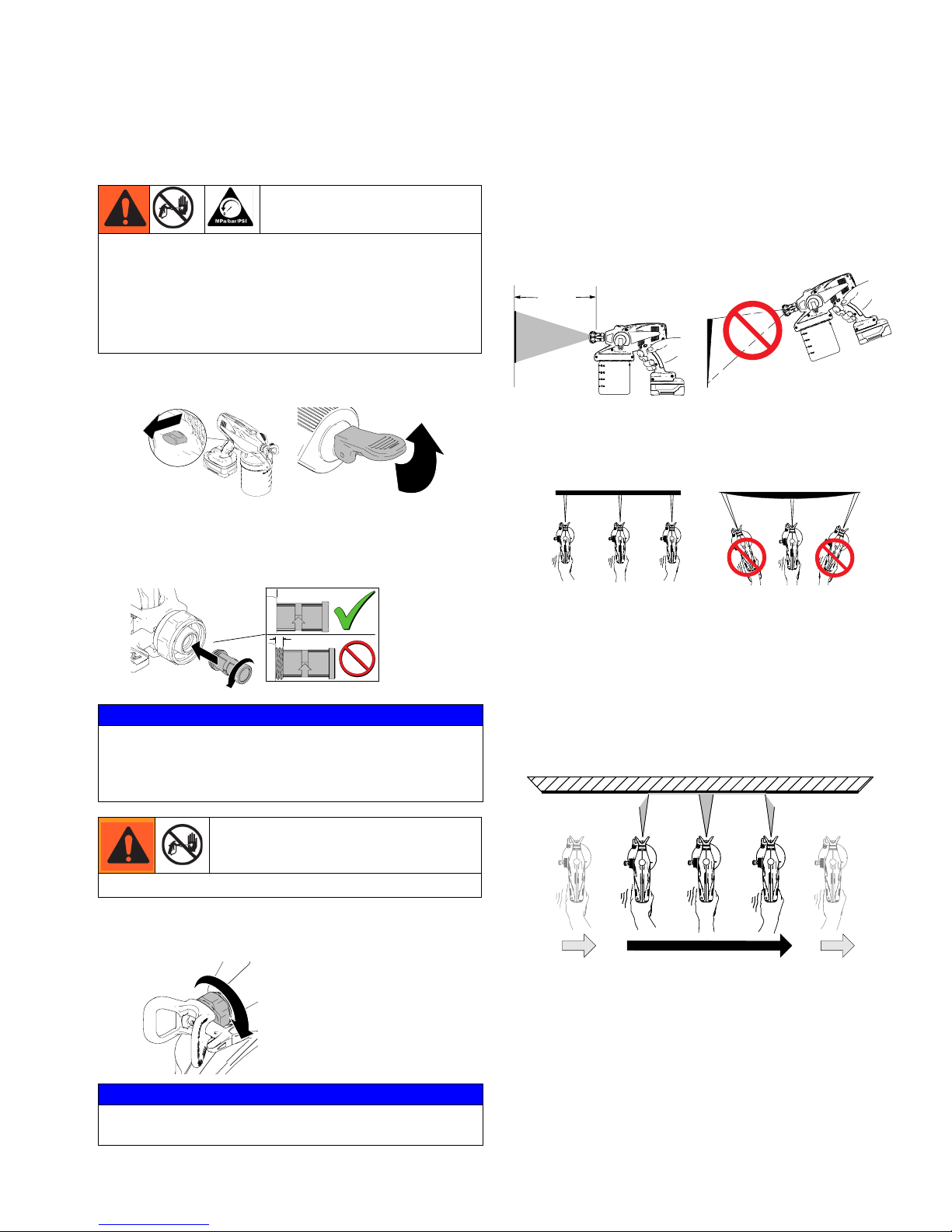
Getting Started with Basic
Techniques
Use a piece of scrap cardboard to practice these basic
spraying techniques before you begin spraying the surface.
• Hold sprayer 10 in. (25 cm) from surface and aim
straight at surface. Tilting sprayer to direct spray angle
causes an uneven finish.
(25 cm)
10 in.
even
finish
thick
thin
uneven
finish
ti14780a
ti18863a
• Flex wrist to keep sprayer pointed straight. Fanning
sprayer to direct spray at angle causes uneven
finish.
even finish thin thick thin
ti18880a
ti18887a
NOTE: How fast you move the sprayer will affect spray
application. If material is pulsating, you are moving too fast.
If material drips, you are moving too slow. See Trouble-
shooting, page 23.
Triggering Sprayer
Pull trigger after starting stroke. Release trigger before end
of stroke. Sprayer must be moving when trigger is pulled
and released.
Do NOT place hands in front of tip.
3. Screw spray/tip guard assembly onto sprayer. Tighten
retaining nut until completely engaged with sprayer. Do
not overtighten nut.
ti16717a
NOTICE
The spray tip is permanently attached to the spray/tip
guard assembly. Removal will result in damage.
12 3A2853A
ti14988a
ti18886a
Start Moving Pull Trigger Release Trigger
ti14997a
Page 13
Getting Started with Basic Techniques
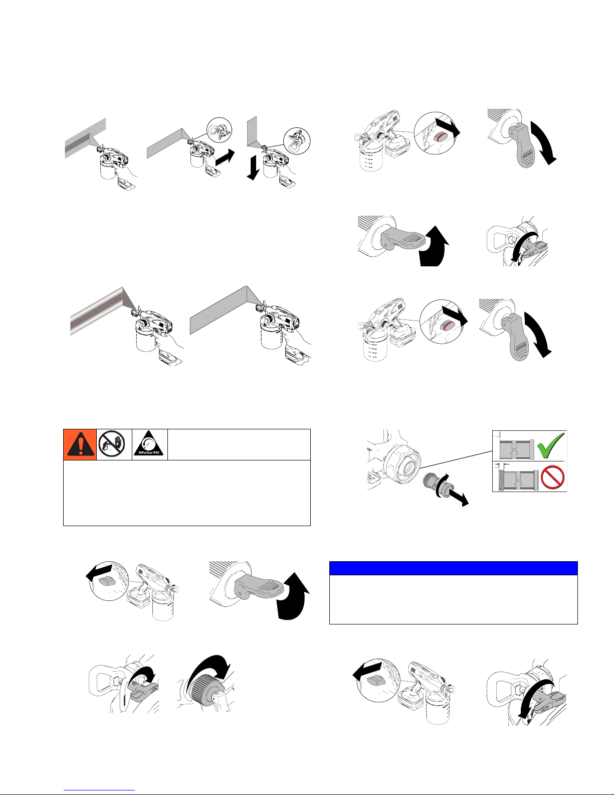
Aiming Sprayer
Aim sprayer at bottom edge of previous stroke, overlapping
each stroke by half.
ti18882a
ti18867a
ti14782a
ti18888a
Spray Pattern Quality
A good spray pattern is evenly distributed as it hits the surface. Adjust pressure control knob so pressure is just high
enough to spray without “tails”. If tails persist at highest
pressure setting, a smaller tip is needed to spray the material or material may need to be thinned.
ti19466a
BAD PATTERN
ti19502a
GOOD PATTERN
Unclogging Spray Tip/Guard
Assembly
3. Aim sprayer at waste area, disengage trigger lock, and
put prime/spray valve DOWN to spray position. Pull
trigger to clear clog.
ti16701a
ti18874a
ti14995a
4. Engage trigger lock. Put prime/spray valve UP to
release pressure and rotate spray tip back to SPRAY
position.
ti14994a
ti16700a
ti16992a
5. Disengage trigger lock, put prime/spray valve DOWN
to spray position, and resume spraying.
ti18874a
ti14995a
ti16701a
6. If spray tip is still clogged, you may have to repeat
steps 1 - 5 and rotate the spray tip from SPRAY to
UNCLOG several times. Repeat step 1 to release pressure, remove and clean spray tip filter, or replace with
new spray tip/guard assembly.
Do not operate or spray near children. Do not aim the
sprayer at, or spray any person or animal. Keep hands
and other body parts away from discharge. For
example, do not try to stop leaks with any part of the
body.
1. To unclog spray tip clog, engage trigger lock and put
prime/spray valve UP to release pressure.
ti16700ati18866a
2. Reverse spray tip to UNCLOG position. Turn pressure
control knob to maximum pressure setting.
ti14991a
ti16704a
ti14989a
NOTE: Spray tip filter assembly is reverse-threaded:
Turn left (or counter-clockwise) to install.
Turn right (or clockwise) to remove.
NOTICE
Make sure spray tip filter is completely screwed into the
spray/tip guard assembly to avoid damage to the filter.
Do not use a damaged filter or poor sprayer performance
may result.
7. When obstruction is cleared, engage trigger lock and
rotate spray tip back to SPRAY position.
ti18866a
ti16992a
3A2853A 13
Page 14
Shutdown and Cleaning
Shutdown and Cleaning
NOTICE
Failure to properly clean sprayer after each use will result
in hardened materials, damage to the sprayer, and the
warranty will no longer be valid.
Flushing Sprayer
Use only water-based materials. Do not use materials
which state “FLAMMABLE” on the packaging. For more
information about your material, request MSDS from distributor or retailer.
Spraying certain materials may cause static build-up
in the sprayer that can result in static shock to the
user. If this occurs, first ensure the material has a flash
point greater than 100° F (38° C) and does not state that it
is FLAMMABLE anywhere on the package. If still feeling a
static shock, the material likely contains a non-mineral
spirits fluid such as, but not limited to, xylene, toluene, or
naphtha, which can build up static. Switch to an alternative material.
Keep spray area well-ventilated. Keep a good supply of
fresh air moving through the area.
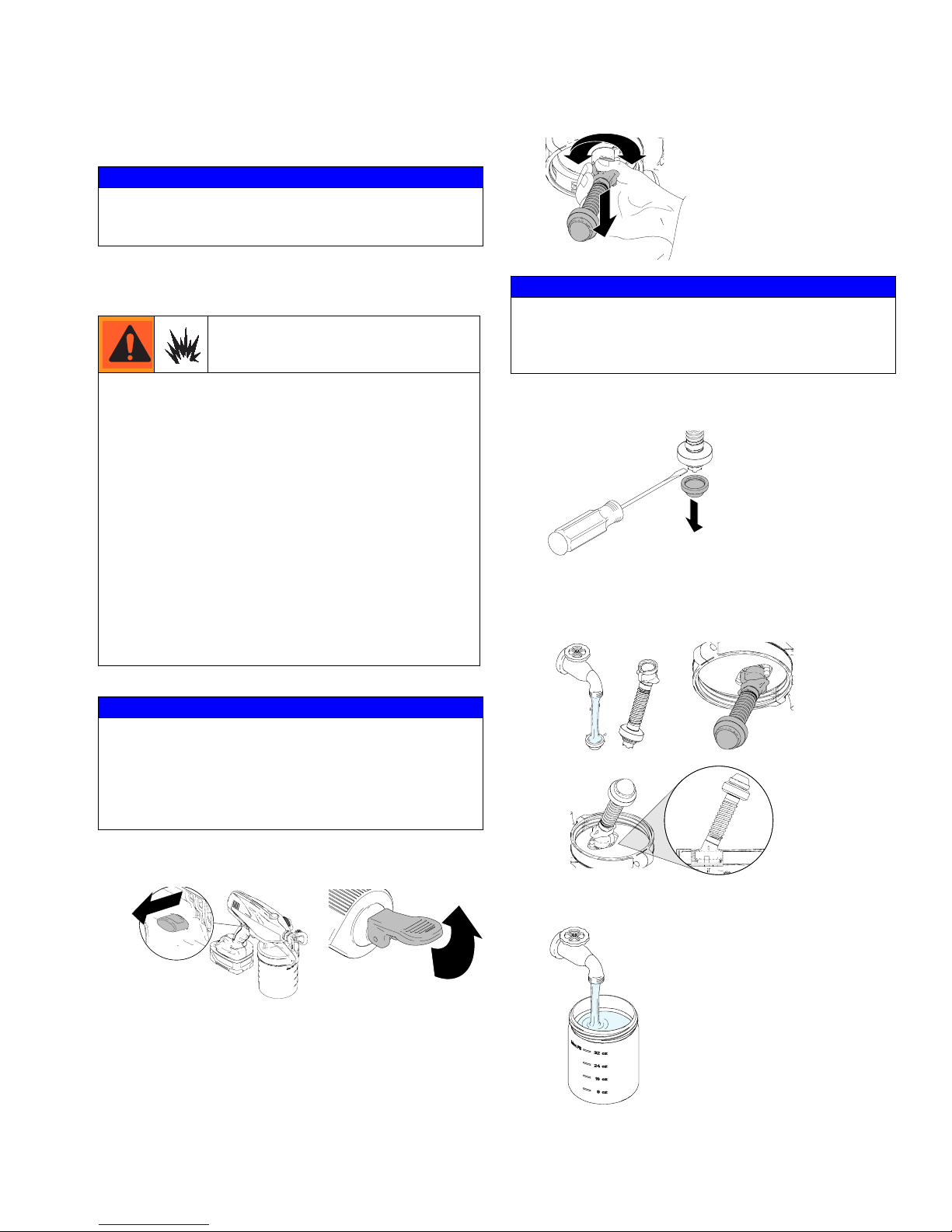
3. Remove flexible suction tube as shown below.
ti19033a
NOTICE
When removing flexible suction tube from sprayer, make
sure to pull directly on top fitting of flexible suction tube.
Flexible suction tube will become damaged if pulled from
bottom or on flexible portion.
4. Use screwdriver to pry suction tube strainer from flexible suction tube.
ti18952a
5. Clean flexible suction tube and suction tube strainer
with water (or flushing fluid) and a brush every time
you flush the sprayer. Reconnect flexible suction tube
and suction tube strainer and orient as shown.
NOTICE
Protect the internal parts of this sprayer from water.
Do not submerge the sprayer in cleaning fluid. Openings
in shroud allow cooling of mechanical parts and electronics inside. If water or cleaning fluid gets into these openings, the sprayer could malfunction or become
permanently damaged.
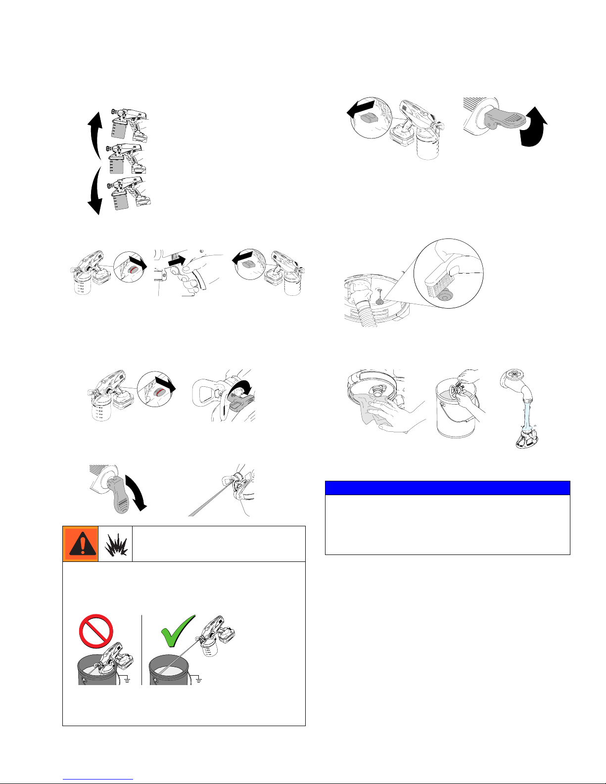
1. Engage trigger lock and pull prime/spray valve UP to
release pressure.
ti18866a
ti16700a
ti14999a
2. Remove material cup and return excess material to
proper container. If used, properly dispose the material
cup liner.
ti18859a
ti15002a
ti19467a
ti19463a
6. Clean material cup if not using a liner, and fill with
water or appropriate flushing fluid.
ti15001a
14 3A2853A
Page 15
Shutdown and Cleaning
7. Reconnect material cup and shake sprayer to move
clean water around and clean all areas inside of material cup.
ti15441a
8. Disengage trigger lock and trigger sprayer for approximately 15 seconds. Engage trigger lock.
ti18874a
ti16716a
ti18866a
9. Discard contaminated fluid and refill with appropriate
flushing fluid.
10. Disengage trigger lock, reverse Spray Tip to UNCLOG
position, and pull trigger for 5 seconds to prime
sprayer.
12. Engage trigger lock and put prime/spray valve UP to
release pressure.
ti16700a
ti18866a
ti14994a
NOTE: Air vent holes or the air vent valve (as your
model is equipped) allow air to flow into the material
cup while spraying to prevent loss of fluid flow.
13. Remove material cup and discard used fluid. Remove
air vent valve, clean, and reinstall.
ti18876a
14. Remove spray/tip guard assembly and clean with
water or flushing fluid. A soft brush can be used to
loosen and remove dried material if needed.
ti18874a
ti14991a
11. Put prime/spray valve DOWN to spray position. Trigger
sprayer into waste area until no paint appears in water
or flushing fluid.
ti16701a
ti15425a
ti16713a
To avoid serious injury or damage to equipment, do not
expose the sprayer electronics to flushing solvents. Keep
sprayer at least 10 in. (25 cm) above the rim of the con-
tainer when flushing.
ti19009a
ti15529a
Keep spray area well-ventilated. Keep a good supply of
fresh air moving through the area. When flushing with solvents, always ground the sprayer and waste container.
ti15703a
ti15705a
ti15547a
NOTICE
The spray tip is permanently attached to the guard.
Removing the spray tip from the guard will result in damage to the spray tip assembly. Do not store spray/tip
guard assembly or flexible suction tube in solvent other
than mineral spirits. Damage to parts may occur.
3A2853A 15
Page 16
Storage
Cleaning Sprayer Exterior
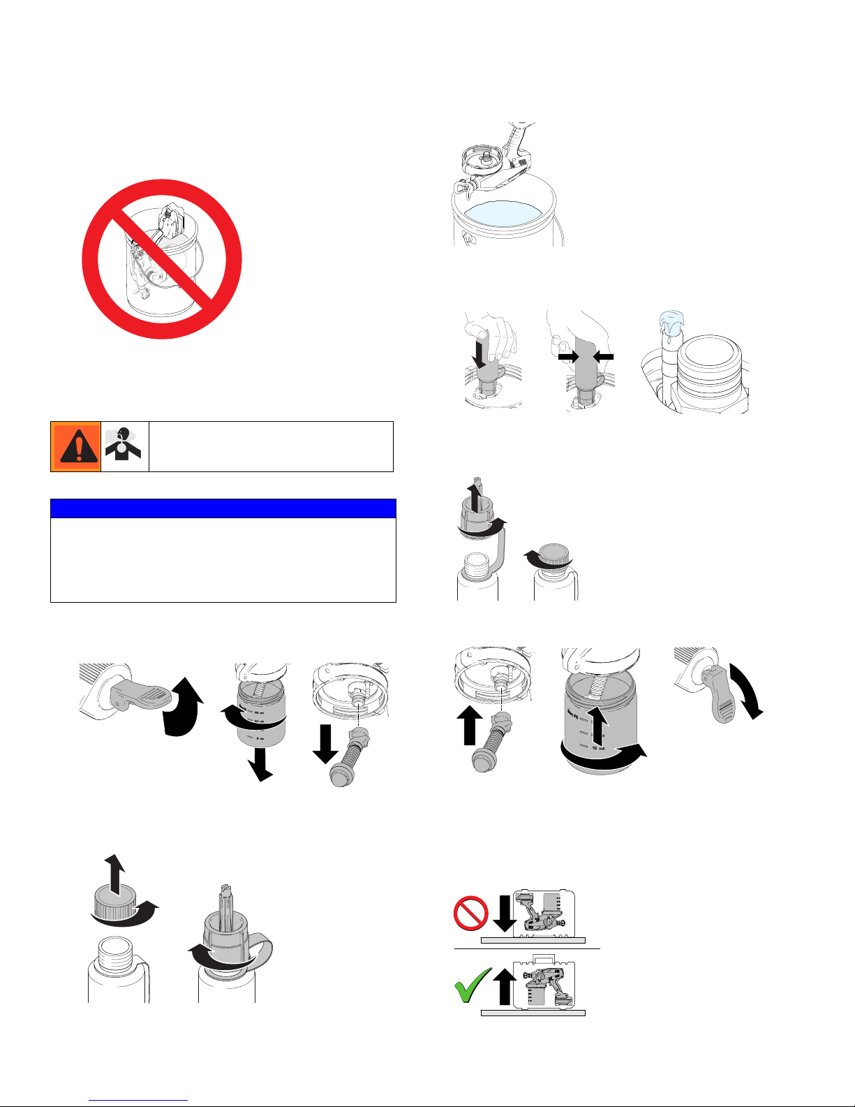
Wipe paint off outside of sprayer using a soft cloth moistened with water or flushing fluid. Do NOT submerge the
sprayer.
ti18879a
Storage
NOTICE
Failure to store sprayer with Pump Armor will result in
operational problems the next time you spray. Always
circulate Pump Armor through the sprayer after cleaning.
Water left in the sprayer will corrode and damage the
pump.
1. Lift prime/spray valve UP to the prime position.
Remove material cup and flexible suction tube.
3. Hold sprayer upside-down over a waste container.
ti18862a
4. Insert Pump Armor nozzle over material inlet and push
firmly until it stops. Squeeze cleaning bottle until Pump
Armor flows out drain tube.
ti18066a
ti18177a
5. Remove Pump Armor nozzle and replace
child-resistent cap and tighten securely for storage.
ti18069a
6. Attach flexible suction tube and material cup. Push
valve DOWN to spray position.
ti16700a
ti18869a
2. Remove child-resistent cap. Thread nozzle onto Pump
Armor bottle. NOTE: For best results, make sure bottle
is full.
ti18067a
16 3A2853A
ti16701a
ti18872a
ti18871a
ti18870a
7. Recharge battery to full charge before storage. See
Charging the Battery, page 6.
8. Store sprayer indoors in a cool, dry place. Store in
an upright position only. Never store sprayer with
material in the cup.
ti18885a
Page 17
Replacement Parts
Replacement Parts
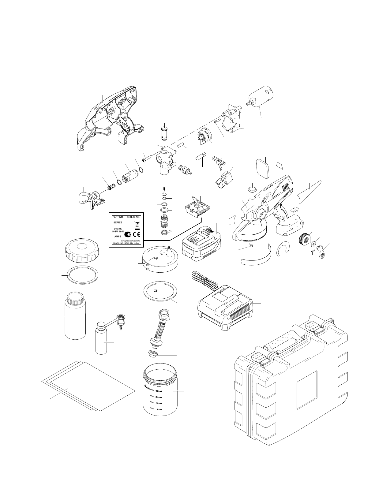
Models 16N664, 16N665, 16N666, 16N668, 16N669, 16N670
32
51
52
24
10
9
7
8
7
6
5
12
14
16
56
57
11
13
15
1717
26
25
27
31
29
28
37
33
32
41
46
38
59
30
36
31
34
35
40
39
42
43
45
44
60
1
2
53
3A2853A 17
20
21
22
4
3
23
ti19608a
Page 18
Replacement Parts
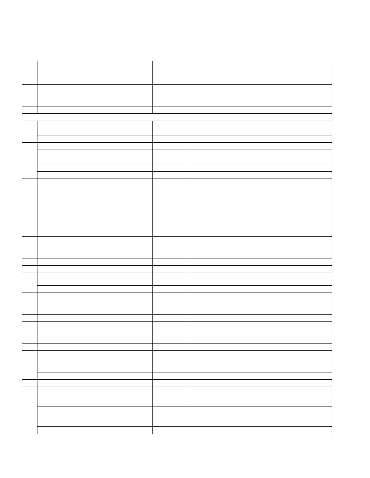
Parts List - Models 16N664, 16N665, 16N666, 16N668, 16N669, 16N670
If you have this model sprayer
Ref.
1 All models 243103 Pump Armor (32 oz)
2 Non-Euro Models 16N668,16N669,16N670 16M816 Startup/Storage Kit
3 Blue Case Models 16N668,16N669,16N670 16P458 Storage Case
4 100-120V Models: 16N668 16D559 Battery Charger
5 All models PST211 211 Spray Tip/Guard Assembly
6 All models 24E376 1 pack Spray Tip Filter
7 All models 108195 Needle Assembly O-ring
8 All models 262437 Needle Assembly Kit: includes parts 7 (qty. 2), 8
9 All models 115478 Screw
10 All models 16M865 Complete Pump Assembly w/Adjustable Prime/Spray Valve:
11 All models 262602 Inlet valve Repair Kit; includes 11, 12, 13
12 All models 262602 Inlet valve Repair Kit; includes 11, 12, 13
13 All models 262602 Inlet valve Repair Kit; includes 11, 12, 13
14 All models 109576 O-ring
15 All models 119790 O-ring
16 All models 16P151 Inlet/Outlet Valve Repair Kit: includes parts 11-17, 24
17 All models 106553 Suction Tube O-ring
20 All models 16J731 Sprayer Cup Seal
21 All models 16P121 Flexible Suction Tube Kit: includes parts 17 (qty. 2), 21, 22
22 All models 16N522 Flexible Suction Tube Strainer
23 All models 16D560 32 oz Material Cup: includes parts 23, 51, 52
24 All models 16P151 Inlet/Outlet Valve Repair Kit: includes parts 11-17, 24
25 All models 16M873 Adjustable Prime/Spray Valve Repair Kit: includes 25, 42-45
26 All models 16M865 Complete Pump Assembly w/Adjustable Prime/Spray Valve:
27 All models 16M865 Complete Pump Assembly w/Adjustable Prime/Spray Valve:
(model number is the same as the part number,
which is between the battery and the sprayer)
Model 16N670 262843 Sprayer Replacement Kit: includes par ts 2, 7-20, 24-45, 56, 57, 59, 60
Models 16N664, 16N665 262845 Sprayer Replacement Kit: includes par ts 2, 7-20, 24-45, 56, 57, 59, 60
Model 16N666 262846 Sprayer Replacement Kit: includes par ts 2, 7-20, 24-45, 56, 57, 59, 60
Models 16N668, 16N669 262847 Sprayer Replacement Kit: includes par ts 2, 7-20, 24-45, 56, 57, 59, 60
Euro Models 16N664, 16N665, 16N666 16P358 Startup/Storage Kit
Black Case Models 16N664, 16N665, 16N666 16P457 Storage Case
230V Models: 16N664, 16N665, 16N666 16D799 Battery Charger
230V Models: 16N669, 16N670 16G615 Battery Charger
All models PST213 213 Spray Tip/Guard Assembly
All models PST315 315 Spray Tip/Guard Assembly
All models PST411 411 Spray Tip/Guard Assembly
All models PST413 413 Spray Tip/Guard Assembly
All models PST515 515 Spray Tip/Guard Assembly
All models PST517 515 Spray Tip/Guard Assembly
Models 16N664, 16N665, 16N666 PST309 309 Spray Tip/Guard Assembly
All models 24F039 3 pack Spray Tip Filter
All models 16M868 Pump Housing Only: includes parts 10, 26, 27, 44
All models 16M868 Pump Housing Only: includes parts 10, 26, 27, 44
All models 16M868 Pump Housing Only: includes parts 10, 26, 27, 44
Order Part
Number:
includes parts 10, 11-17, 24-28, 44
16D561 48 oz Material Cup: includes par ts 23, 51, 52
includes parts 10, 11-17, 24-28, 44
includes parts 10, 11-17, 24-28, 44
(Parts List continues on next page)
Description
18 3A2853A
Page 19
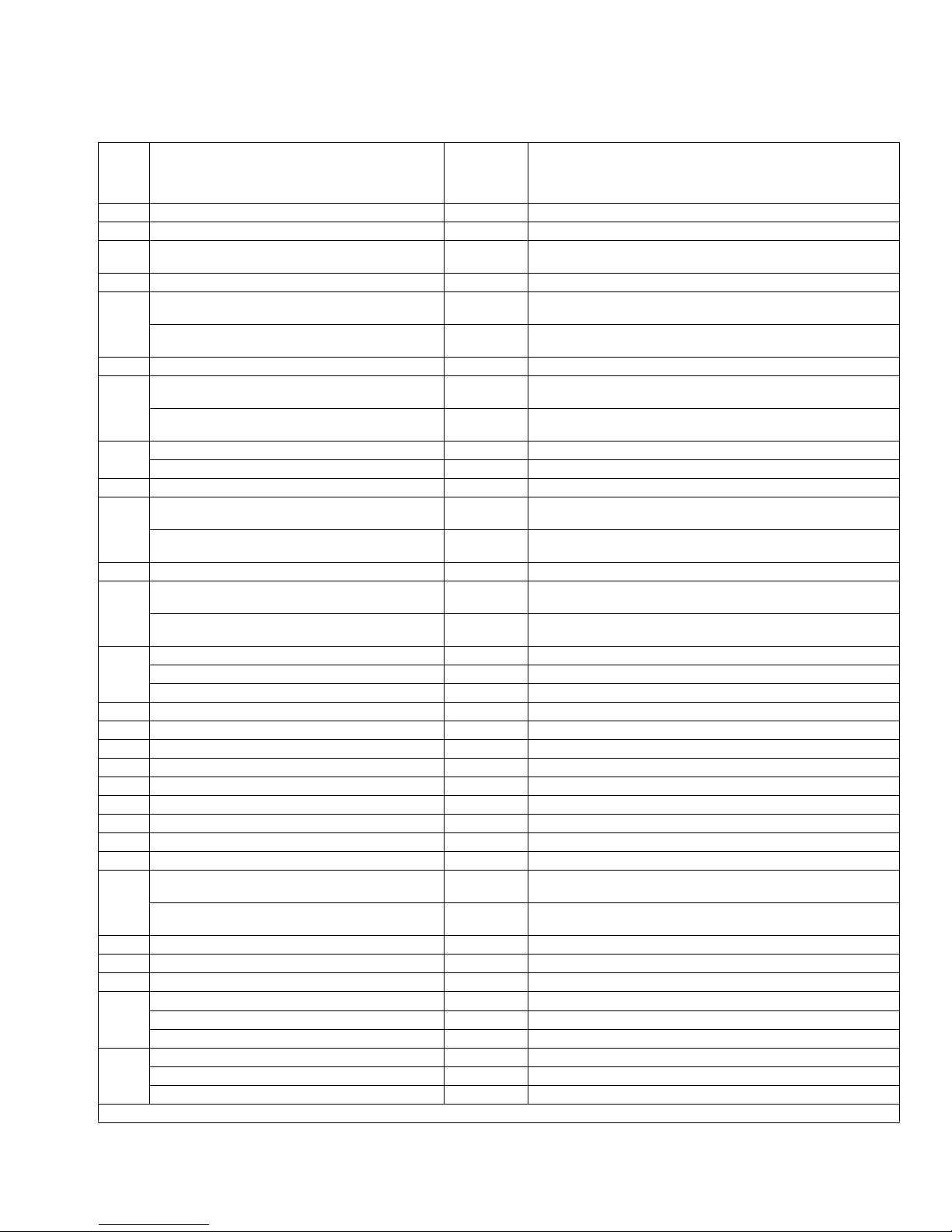
Replacement Parts
Parts List - Models 16N664, 16N665, 16N666, 16N668, 16N669, 16N670 (Continued)
If you have this model sprayer
Ref.
28 All models 16M863 Reciprocator Assembly Kit: includes parts 28, 44
29 All models 108326 Motor Mount Screw
30 All models 16M924 Drive Housing Assembly Kit:
31 All models 16M861 Motor/Control Board Kit: includes parts 29, 31, 33, 34, 44
32 Models 16N668, 16N669, 16N670 16P461 Enclosure Replacement Kit:
33 All models 16N928 Switch Kit: includes parts 33, 34
34 Models 16N668, 16N669, 16N670 16P461 Enclosure Replacement Kit:
35 Models 16N668, 16N669, 16N670 16E859 Made in USA Label
36 All models 16C936 Outlet Valve Access Plug
37 Models 16N668, 16N669, 16N670 16P461 Enclosure Replacement Kit:
38 All models 119236 Enclosure Screw
39 Models 16N668, 16N669, 16N670 16P461 Enclosure Replacement Kit:
40 Model 16N670 16N556 Side Brand Label
41 All models 16R890 Front Brand Label
42 All models 16M873 Adjustable Prime/Spray Valve Repair Kit: includes parts 25, 42-45
43 All models 16M873 Adjustable Prime/Spray Valve Repair Kit: includes parts 25, 42-45
44 All models 119956 Pin
45 All models 262604 Prime Valve Handle: includes parts 44, 45
46 All models 16D558 Battery
51 All models 24D425 Material Cup Cover: includes parts 51, 52
52 All models 16C650 Seal for Material Cup
53 All models 16D562 Cup Liner Replacement (10 pack)
56 Models 16N668, 16N669, 16N670 16P461 Enclosure Replacement Kit:
57 All models 16M890 Air Vent Valve
59 Models 16N664, 16N665, 16N668, 16N669, 16N670 16R891 Cup Lip Brand Label
60 All models 16R889 Pressure Control Label
Not
Shown
Not
Shown
▲ Replacement Danger and Warning labels, tags, and cards (Not Shown) are available at no cost.
(model number is the same as the part number,
which is between the battery and the sprayer)
Models 16N664, 16N665, 16N666 16P462 Enclosure Replacement Kit:
Models 16N664, 16N665, 16N666 16P462 Enclosure Replacement Kit:
Models 16N664, 16N665, 16N666 16F636 Made in USA Label
Models 16N664, 16N665, 16N666 16P462 Enclosure Replacement Kit:
Models 16N664, 16N665, 16N666 16P462 Enclosure Replacement Kit:
Models 16N664, 16N665 16P157 Side Brand Label
Models 16N668, 16N669 16P159 Side Brand Label
Models 16N664, 16N665, 16N666 16P462 Enclosure Replacement Kit:
All Models ▲16P459 Warning Labels Replacement Kits ENG/FRE/SPA
All Models ▲16P002 Warning Labels Replacement Kits CHI/JAP/KOR
All Models ▲16P003 Warning Labels Replacement Kits SPA/POR/ITA
Models 16N664, 16N665, 16N666 ▲16P207 Sprayer Enclosure Warning Label Kit
Models 16N664, 16N665, 16N666 ▲24E552 Battery Warning Label Kit
Models 16N664, 16N665, 16N666 ▲24E553 Charger Warning Label Kit
Order Part
Number:
Description
includes parts 9 (qty. 4), 29 (qty. 2), 30, 44
includes parts 32, 34-37, 38 (qty. 10), 39, 44, 56, 57
includes parts 32, 34-37, 38 (qty. 10), 39, 44, 56, 57
includes parts 32, 34-37, 38 (qty. 10), 39, 44, 56, 57
includes parts 32, 34-37, 38 (qty. 10), 39, 44, 56, 57
includes parts 32, 34-37, 38 (qty. 10), 39, 44, 56, 57
includes parts 32, 34-37, 38 (qty. 10), 39, 44, 56, 57
includes parts 32, 34-37, 38 (qty. 10), 39, 44, 56, 57
includes parts 32, 34-37, 38 (qty. 10), 39, 44, 56, 57
includes parts 32, 34-37, 38 (qty. 10), 39, 44, 56, 57
includes parts 32, 34-37, 38 (qty. 10), 39, 44, 56, 57
3A2853A 19
Page 20
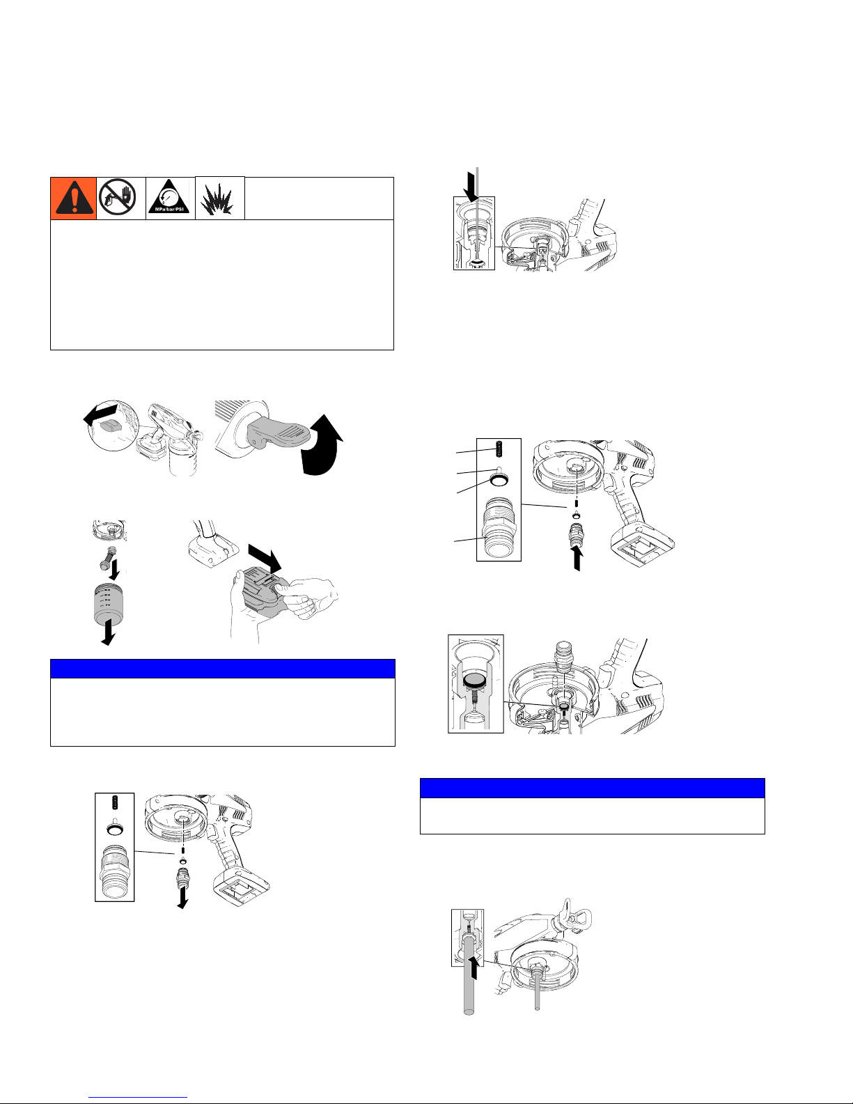
Inlet Valve Fitting Removal/Service
Inlet Valve Fitting
Removal/Service
This equipment stays pressurized until pressure is
manually relieved. To help prevent serious injury from
pressurized fluid, such as skin injection, splashing fluid
and moving parts, follow the Pressure Relief
Procedure when you stop spraying and before
cleaning, checking, or servicing the equipment.
Move sprayer to a non-hazardous area before servicing.
1. Engage trigger lock and pull prime/spray valve UP to
release pressure.
ti18866a
2. Remove material cup, flexible suction tube, and battery.
ti16700a
5. Use a thin wire less than 1/16 in. (such as a paper clip)
to check that the outlet valve fitting moves freely. If
valve does not move freely, perform Outlet Valve Fit-
ting Repair, page 21.
ti18898a
Installation
NOTE: Before installing, make sure o-ring (c) is installed on
poppet valve (b). A needle-nose pliers can also be used to
install parts (a - c).
1. Place poppet valve (b) with spring (a) on top of inlet
valve fitting (d). Push inlet fitting up into pump cavity.
a
b
c
ti18895a
ti18896a
NOTICE
When removing flexible suction tube from sprayer, make
sure to pull directly on top fitting of flexible suction tube.
Flexible suction tube will become damaged if pulled from
bottom or on flexible portion.
3. Hold sprayer upside-down and use wrench to loosen
and remove inlet valve fitting, inlet valve, and spring.
ti18897a
NOTE: Make sure the spring also comes out. Use needle-nose pliers to remove if needed. Inlet cavity should
be completely empty (as shown below).
d
ti15502a
ti18899a
2. Hold inlet in place and turn sprayer upside-down.
Remove inlet valve fitting and visually check to see that
inlet valve has seated correctly.
ti18900a
3. Replace inlet fitting and use wrench or socket to
tighten to 10 ft-lb (14 N•m).
NOTICE
Do NOT over-tighten inlet valve fitting. Damage to the
equipment will occur.
4. Use a pencil or thin rod to lightly push on inlet valve to
make sure it moves up and down freely. Perform Start-
ing New Job procedure, page 10.
ti15509a
4. Clean as much excess material from inlet cavity as
possible. Make sure you also clean spring (a), inlet
valve (b), o-ring (c), and top of inlet valve fitting (d).
20 3A2853A
ti18883a
Page 21
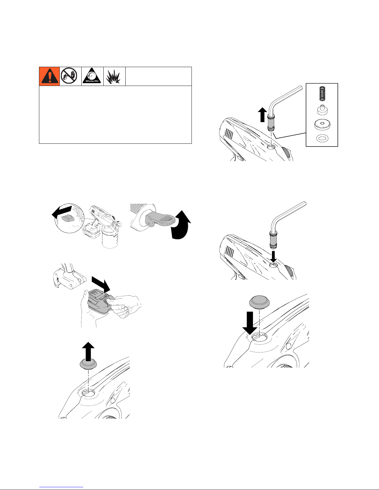
Outlet Valve Fitting Repair
Outlet Valve Fitting Repair
This equipment stays pressurized until pressure is
manually relieved. To help prevent serious injury from
pressurized fluid, such as skin injection, splashing fluid
and moving parts, follow the Pressure Relief
Procedure when you stop spraying and before
cleaning, checking, or servicing the equipment.
Move sprayer to a non-hazardous area before servicing.
4. Use tool (supplied) to loosen and remove outlet
valve fitting. Make sure old o-ring, seat, outlet valve
fitting, and spring are out of pump outlet cavity.
ti15506a
NOTE: Before doing any repair to pump, perform
Flushing Sprayer procedure, page 14.
Removal
1. Engage trigger lock and pull prime/spray valve UP
to release pressure.
ti18866a
2. Remove battery.
ti16700a
ti14996a
ti16745a
ti18903a
Installation
1. Screw outlet valve fitting into threads. Use tool
(supplied) and tighten to 8 ft-lb (11 N•m).
ti15508a
2. Press outlet valve fitting access plug into place.
ti18904a
3. Remove outlet valve fitting access plug.
ti15503a
3A2853A 21
ti15507a
ti18902a
ti18901a
Page 22
General Service
General Service
See manual 3A1884 (available at www.graco.com) for
complete instructions on properly servicing your sprayer.
If you have opened the sprayer clamshell and do not have
access to manual 3A1884, follow the instructions below to
reduce the risk of errors when assembling the sprayer
clamshell.
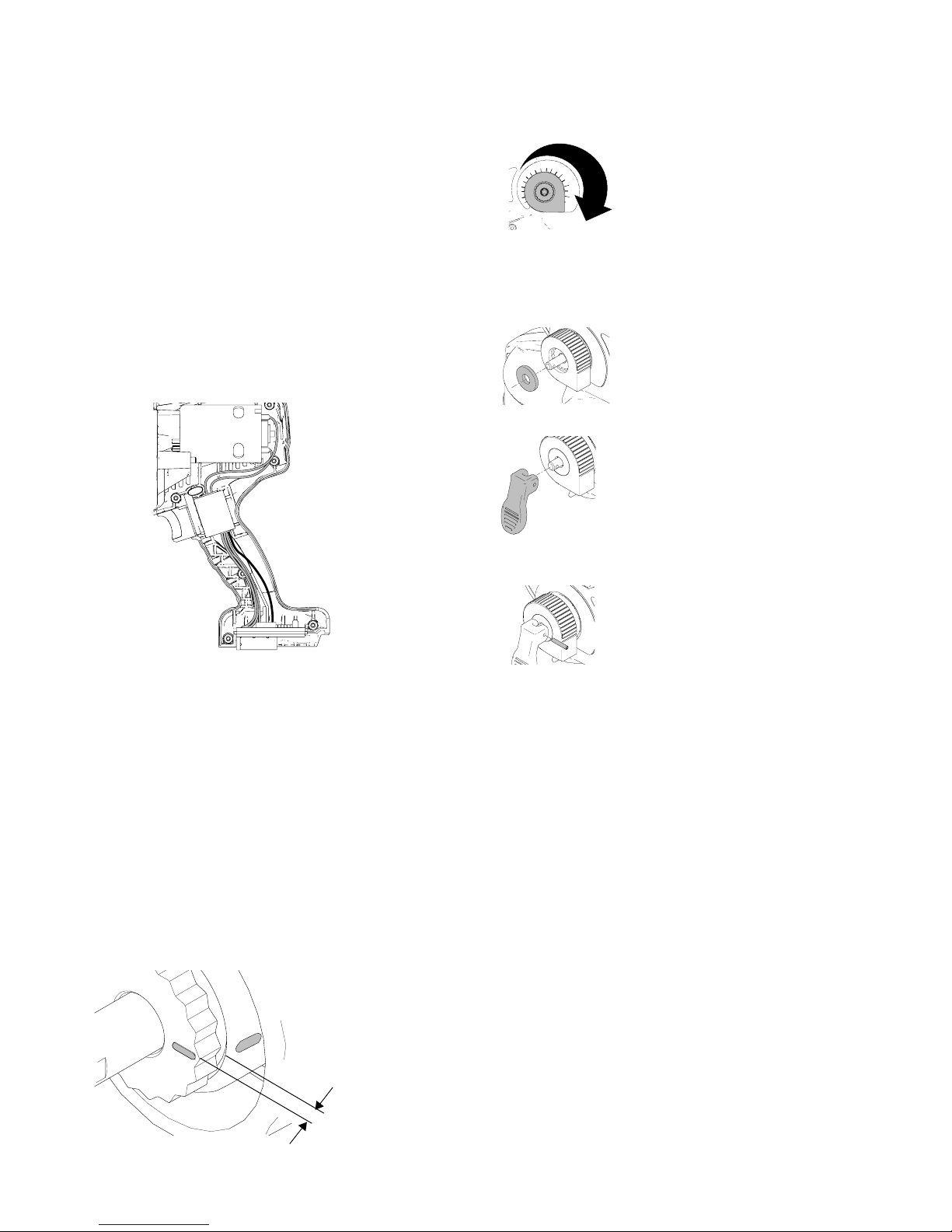
Wiring
Align switch in enclosure, install control board, and route wires
as shown below. NOTE: Make sure wires will not be pinched
when enclosure halves are put together.
ti19748a
4. Position pressure control knob in fully clockwise position
and press firmly onto retainer.
10
ti19716a
NOTE: You may have to rotate pressure control knob
slightly counter-clockwise to fully engage pressure control
knob with retainer.
5. Install washer onto pressure control knob.
ti19717a
6. Install valve handle onto stem.
ti19713a
7. Insert pin into valve handle. Use pliers to press pin into
hole.
Cordless models
Pressure Control Knob
1. Use the pressure control knob as a tool to rotate retainer
fully clockwise (there should be no gap between retainer
teeth and metal valve housing).
NOTE: You may occasionally have to remove, rotate, and
reposition pressure control knob due to stop feature
molded into back of knob.
2. Rotate retainer back (counter-clockwise) until the first
instance that the line and mark are aligned.
3. The valve retainer should now protrude approximately 1/8
in. (.30 cm) out from metal valve housing. Your
prime/spray valve is now calibrated.
1/8 in. (.30 cm)
ti17036a
ti19712a
NOTE: If pin does not assemble, repeat steps 3 - 6 to
ensure pressure control is fully engaged with retainer.
IMPORTANT!
After assembly is complete, perform the following steps to
verify proper operation. If sprayer fails one of the steps, repeat
Pressure Control Knob procedure.
• Verify proper trigger lock operation. Slide trigger lock into
“locked” and “unlocked” position and pull trigger. Trigger
should not move in locked position and sprayer should run
in unlocked position.
• Visually inspect for gaps between enclosure halves. A gap
larger than 1/32 in. could be caused by a pinched wire. If
disassembly and inspection indicates that no wire has
been pinched, carefully reassemble and repeat
verification steps.
• Cordless Sprayers: Verify that battery freely slides onto
sprayer terminals and is locked when fully engaged.
• Verify belt hook operation (if applicable) by sliding hook
completely out and back inside.
• Fill material cup with water and verify unit primes and
sprays. Follow setup instructions in sprayer operation
manual for proper priming and spraying procedure.
• Rotate pressure control knob to make sure it can rotate
fully in both directions.
22 3A2853A
Page 23
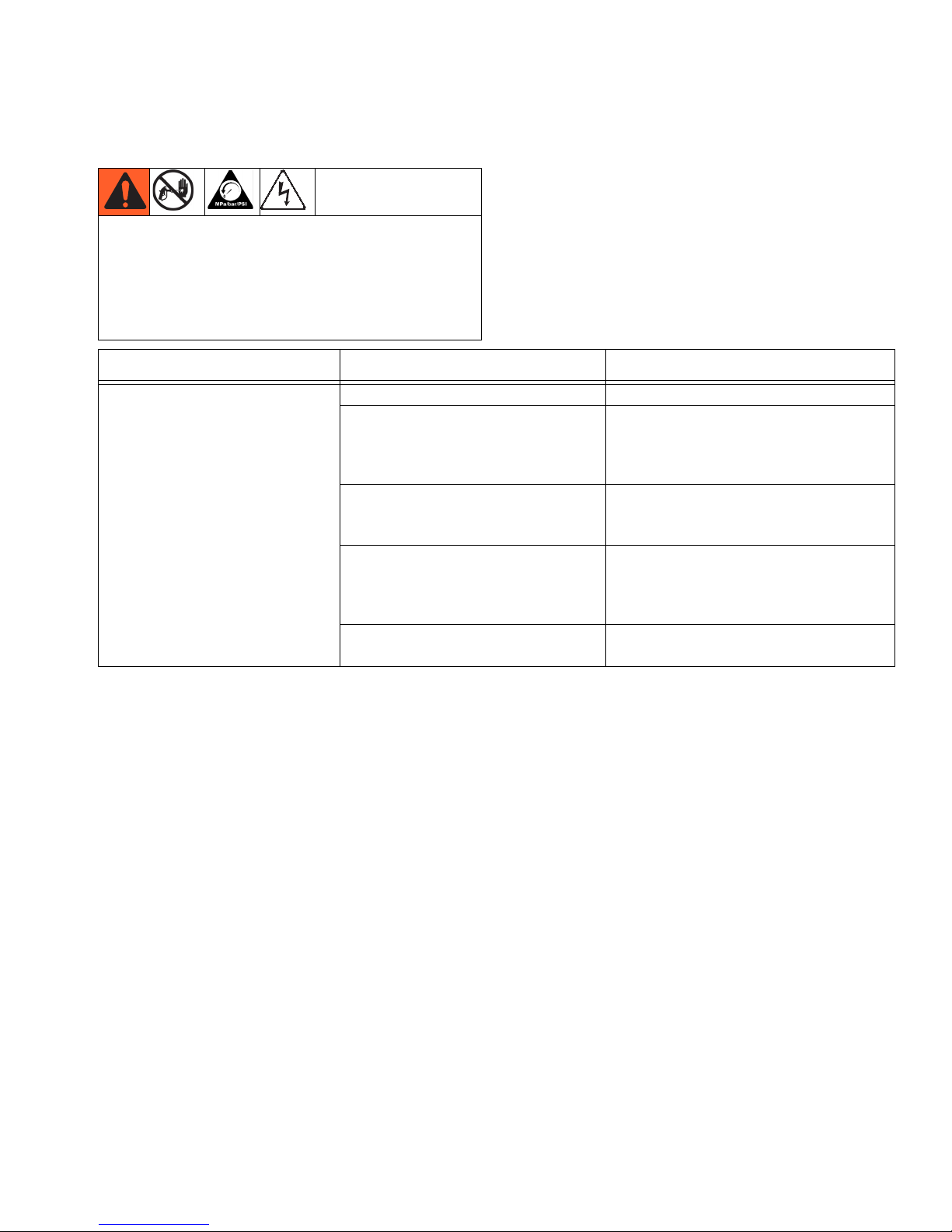
Troubleshooting
Troubleshooting
This equipment stays pressurized until pressure is
manually relieved. To help prevent serious injury from
pressurized fluid, such as skin injection, splashing
fluid and moving parts, follow the Pressure Relief
Procedure when you stop spraying and before
cleaning, checking, or servicing the equipment.
Problem Cause Solution
Check everything in this Troubleshooting Table before
you bring the sprayer to an authorized service center.
Sprayer makes no sound when
trigger is pulled
Trigger is locked. Disengage trigger lock. See page 7.
Sprayer status indicator light is solid
RED when triggering, indicating that
the battery charge is low, or the battery is too cold.
Sprayer status indicator light is flashing RED when triggering, indicating
that the battery is too hot to operate.
Sprayer status indicator light does
not light when sprayer is triggered.
Battery is not installed or is damaged.
Motor/control board kit has reached
maximum life.
Replace with charged battery and place
old battery in charger, or allow battery to
warm up.
Allow battery to cool.
Install battery or replace.
Replace motor/control board kit.
3A2853A 23
Page 24
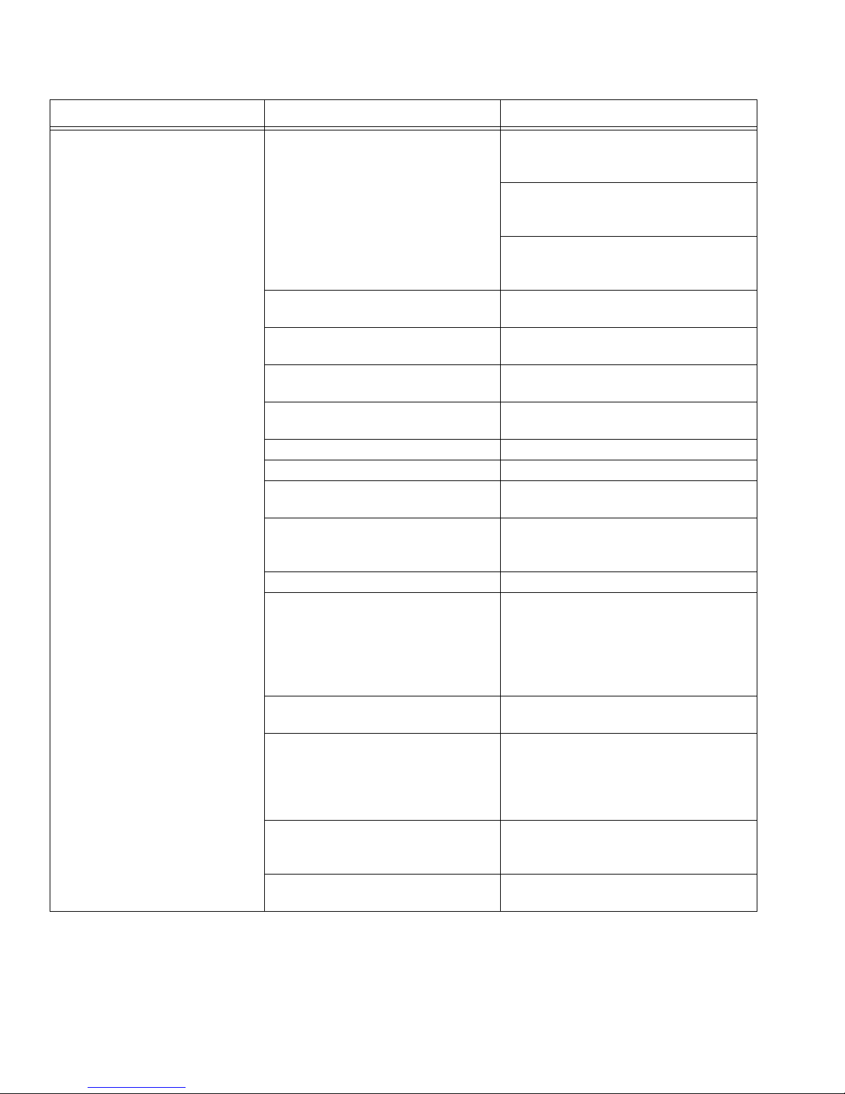
Problem Cause Solution
Troubleshooting
Sprayer makes sound but no
material is sprayed when trigger is
pulled
Sprayer is not primed. Prime the pump. See Starting a New
Job (or Refilling the Material Cup),
page 10.
Use pump access armor storage/startup
tool to clear pump of debris. See Stor-
age, page 16.
Clean air vent holes or the air vent valve
as your model is equipped. See Shut-
down and Cleaning, page 14.
Prime/spray valve is in UP position. Put prime/spray valve DOWN to spray
position.
Flexible suction tube is missing or
improperly installed.
Flexible suction tube strainer or air
Make sure Flexible Suction Tube is
properly installed, page 8.
See Shutdown and Cleaning, page 14.
vent valve or vent holes are clogged.
Flexible suction tube o-rings are
Replace flexible suction tube o-rings.
damaged or missing.
Flexible suction tube is damaged. Replace flexible suction tube.
Spray tip is not in SPRAY position. Turn spray tip to SPRAY position.
Spray tip is clogged. See Unclogging Spray Tip/Guard
Assembly, page 13.
Spray tip filter is clogged. Remove and clean Spray tip filter. See
Unclogging Spray Tip/Guard Assembly, page 13.
Pressure control knob is too low. Turn pressure control knob up.
Sprayer has been tilted too far and
flexible suction tube has lost contact
with material.
Make sure material cup is filled with
material. Rotate flexible suction tube,
page 8. Do not tilt the material cup too
far. Prime the pump. See Starting a new
Job (or Refilling the Material Cup),
page 10.
No or low material in material cup. Refill material cup with material and
prime the pump.
Inlet valve fitting is stuck from
material residue left in sprayer.
Use pump access armor storage/startup
tool to clear pump of debris. See Stor-
age, page 16. If unsuccessful, see Inlet
Valve Fitting Removal/Service, page
20.
Pump is clogged, frozen, or has
debris inside.
See Outlet Valve Fitting Repair, page
21 and Inlet Valve Fitting
Removal/Service, page 20.
Material is leaking from hole in front
Replace needle assembly.
of sprayer.
24 3A2853A
Page 25
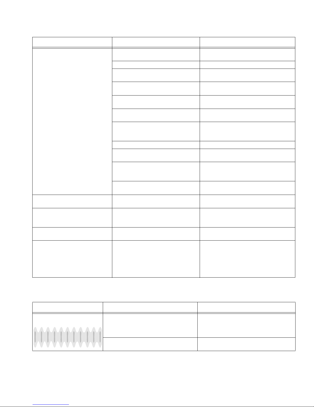
Troubleshooting
Problem Cause Solution
Sprayer sprays with poor results Spray tip is partially clogged. See Unclogging Spray Tip/Guard
Assembly, page 13.
Spray tip is not in correct position. Rotate spray tip to SPRAY position.
Incorrect spray tip for application of
material.
Spray tip filter is partially clogged or
damaged.
Flexible suction tube strainer is partially
clogged.
Spray tip is worn or damaged. Replace spray tip. See Install Spray
Material being sprayed is aerated
because it was shaken.
Pressure control knob is too low. Turn up pressure control knob.
Material being sprayed is too cold to
spray.
Inlet or outlet valve fitting is worn. See Outlet Valve Fitting Repair, page 21
Pressure is set too high for thin material.
Paint leaks from sprayer trigger
area.
Battery is discharged but charger
still displays green light when battery is inserted.
Battery does not last long. Battery life varies with material, spray
Charger status indicator light
remains solid red. Battery does not
charge.
Pump has reached its maximum life. Replace pump.
Damaged battery. Replace battery.
tip size, pressure, and speed setting.
Hot charging environment or damaged
battery.
See Choosing the Correct Tip, page 11.
Clean or replace spray tip filter. See page
13.
Clean or replace flexible suction tube. See
page 14.
Tip/Guard Assembly, page 12.
Do NOT shake material. Stir the material or
check the manufacturer’s recommendation
for the material being sprayed.
Warm material.
and Inlet Valve Fitting Removal/Service,
page 20.
Turn pressure control knob down.
See Charging the Battery, page 6.
See Charging the Battery, page 6.
Unplug charger from outlet for 10 seconds
to reset charger status indicator light.
Attempt to charge again. If problem persists, move charger to cooler environment
or replace battery.
Spray Pattern Diagnostics
Problem Cause Solution
Spray pattern is pulsating: Operator is moving too fast while spraying. Slow speed of movement.
Spray tip or spray tip filter is clogged. Unclog spray tip or clean spray tip filter,
3A2853A 25
page 13.
Page 26
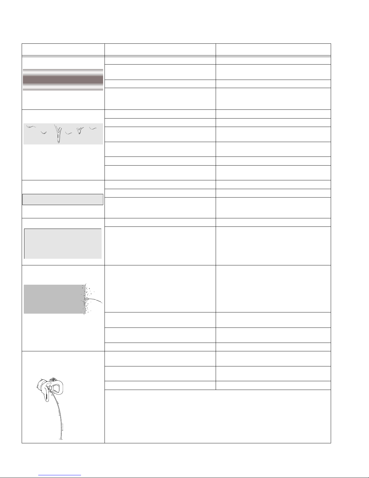
Problem Cause Solution
Spray pattern has tails:
ti15526a
Spray pattern has dripping:
Spray pattern is too narrow:
ti15523a
ti15523a
Troubleshooting
Pressure control knob is too low. Turn up pressure control knob.
Incorrect spray tip for application of
See Choosing the Correct Tip, page 11.
material.
Material not compatible with sprayer. Switch to compatible material.
Inlet or outlet valve fitting is worn. See Outlet Valve Fitting Repair, page 21 and
Inlet Valve Fitting Removal/Service, page
20.
Sprayer is moving too slow for material. Move sprayer faster while spraying.
Sprayer is too close to target surface. Move sprayer away from surface 10 in. (25 cm)
Holding trigger while changing spray
Release trigger when changing directions.
direction.
Incorrect spray tip for application of
See Choosing the Correct Tip, page 11.
material.
Pressure control knob is set too high. Turn down pressure control knob.
Spray tip is worn or damaged. Replace spray tip. See Install Spray
Tip/Guard Assembly, page 12.
Sprayer is too close to target surface. Move sprayer away from surface 10 in. (25 cm)
Incorrect spray tip for application of material. See Choosing the Correct Tip, page 11.
Spray tip is worn or damaged. Replace spray tip. See Install Spray
Tip/Guard Assembly, page 12.
Spray pattern is too wide:
ti15527a
ti15527a
Spray pattern “spits” at the end
or beginning:
ti15525a
ti15525a
Spray tip continues to drip or
ooze material after trigger is
released:
Sprayer is too far away from target surface. Move sprayer closer to surface.
Incorrect spray tip for application of material. See Choosing the Correct Tip, page 11.
Excess material has accumulated on
See Shutdown and Cleaning, page 14.
spray/tip guard assembly.
Spray tip filter is partially clogged or dam-
Clean or replace filter. See page 13.
aged.
Spray tip/guard assembly not threaded completely onto sprayer.
See Install Spray Tip/Guard Assembly, page
12.
Seat is worn. Replace spray tip/guard assembly.
Spray tip filter is partially clogged or dam-
Clean or replace filter. See page 13.
aged.
Spray tip/guard assembly not threaded completely onto sprayer.
See Install Spray Tip/Guard Assembly, page
12.
Seat is worn. Replace spray tip/guard assembly.
If the three solutions above do not solve the problem, replace needle assembly.
ti15528a
ti15528a
26 3A2853A
Page 27
Troubleshooting
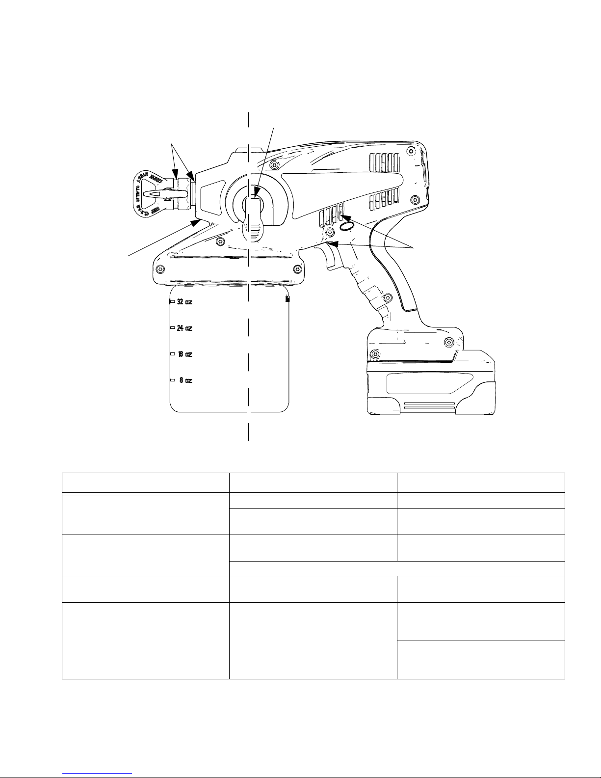
Troubleshooting Leaks
Points A
Point C
Point B
Points D
Problem Cause Solution
Sprayer is leaking fluid at Points A Spray/tip guard assembly is loose. Tighten spray/tip guard assembly.
O-ring inside needle assembly is
worn out.
Sprayer is leaking fluid at Point B O-ring on rear of needle assembly is
worn out.
If 3 solutions above do not stop the leaking, replace needle assembly kit.
Sprayer is leaking fluid at Point C Prime/spray valve assembly is worn
out.
Sprayer is leaking fluid at Points D Pump is worn out. If inlet/outlet valve fittings have not
Replace o-ring (108195).
Replace o-ring (108195).
Replace prime/spray valve assembly.
yet been replaced, replace pump
housing only (16M868).
If inlet/outlet valve fittings have been
replaced once or more, replace complete pump assembly (16M865).
3A2853A 27
Page 28
Technical Data
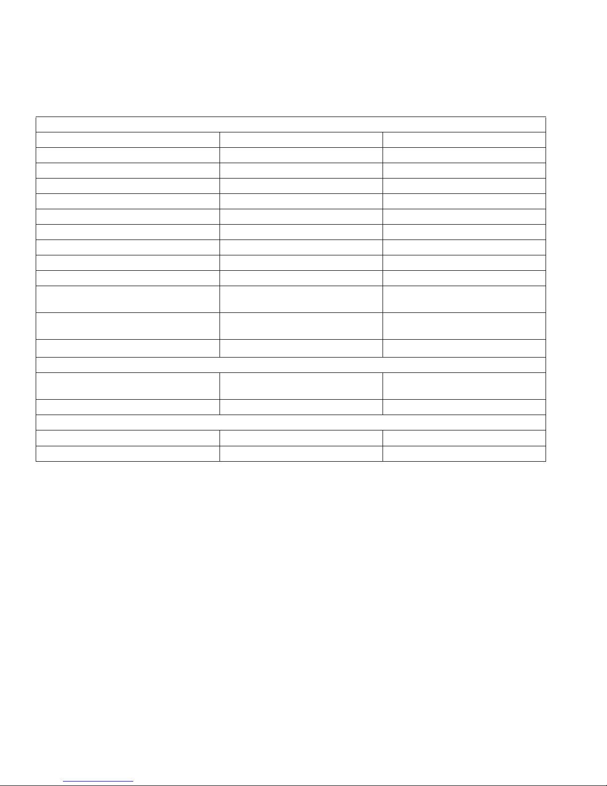
Hand-Held Sprayer (Models 16N664, 16N665, 16N666, 16N668, 16N669, 16N670)
U.S. (Customary) Metric
Adjustable pressure range 1000 - 2000 psi 7.0 - 14 MPa, 69 -138 bar
Maximum working pressure 2000 psi 14 MPa, 138 bar
Weight 6.48 lb 2.94 kg
Dimensions:
Length 13.75 in. 34.9 cm
Width 5.25 in. 13.3 cm
Height 10.25 in. 26.0 cm
Storage temperature range ◆❖ 32° to 113° F 0° to 45° C
Operating temperature range ✔ 40° to 90° F 4° to 32° C
Storage humidity range 0% to 95% relative humidity,
non-condensing
Sound pressure level 73.2 dBa† sound pressure level
84.2 dBa† sound power level
Vibration level acceleration
Charger:
Charging time 45 minutes to 80%,
Power source 120 VAC 120 VAC
Battery (Lithium Ion):
Voltage (DC)
Capacity 2.4 Ah, 43.2 Wh 2.4 Ah, 43.2 Wh
Less than 5.5 feet/s
75 minutes to 100%
20 V Maximum
2
†† Less than 1.7 m/s2††
†††
0% to 95% relative humidity,
non-condensing
73.2 dBa† sound pressure level
84.2 dBa† sound power level
45 minutes to 80%,
75 minutes to 100%
20 V Maximum
Technical Data
◆ Pump damage will occur if fluid freezes in pump.
❖ Damage to plastic parts may result if impact occurs in low temperature conditions.
✔ Changes in paint viscosity at very low or very high temperatures can affect sprayer performance.
† per ISO 9614-2 measured at 3.3 feet (1m)
†† per ISO 5349, no load condition
††† Maximum measured battery voltage is 20V. Average running voltage is 18V.
28 3A2853A
Page 29
Preferred Material Settings Log
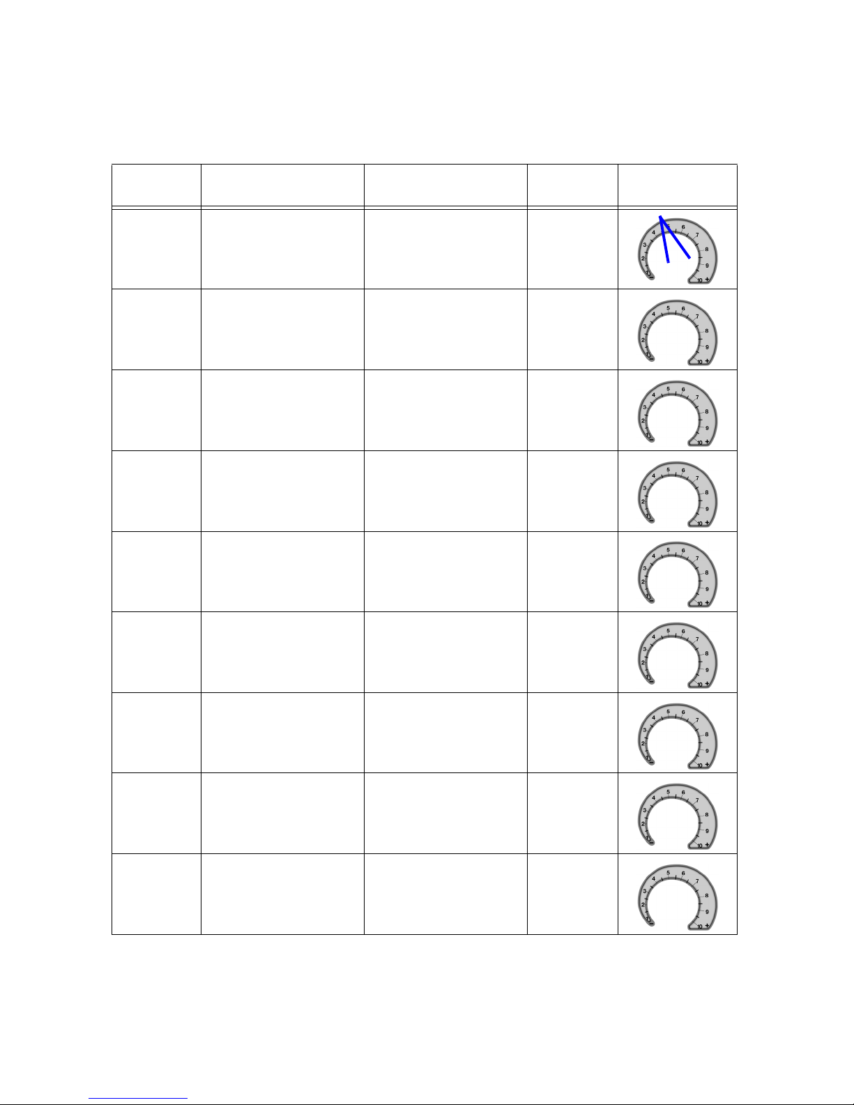
Preferred Material Settings Log
Date
03/24/2011 Crown molding PST517
EXAMPLE
Item
Sprayed
Material
Sprayed
Spray
Tip
Pressure Setting
(Mark Dial)
3A2853A 29
Page 30

Notes
Notes
30 3A2853A
Page 31

Notes
Notes
3A2853A 31
Page 32

Graco Standard Warranty
Graco warrants all equipment referenced in this document which is manufactured by Graco and bearing its name to be free from defects in
material and workmanship on the date of sale to the original purchaser for use. With the exception of any special, extended, or limited warranty
published by Graco, Graco will, for a period of twelve months from the date of sale, repair or replace any part of the equipment determined by
Graco to be defective. This warranty applies only when the equipment is installed, operated and maintained in accordance with Graco’s written
recommendations.
This warranty does not cover, and Graco shall not be liable for general wear and tear, or any malfunction, damage or wear caused by faulty
installation, misapplication, abrasion, corrosion, inadequate or improper maintenance, negligence, accident, tampering, or substitution of
non-Graco component parts. Nor shall Graco be liable for malfunction, damage or wear caused by the incompatibility of Graco equipment with
structures, accessories, equipment or materials not supplied by Graco, or the improper design, manufacture, installation, operation or
maintenance of structures, accessories, equipment or materials not supplied by Graco.
This warranty is conditioned upon the prepaid return of the equipment claimed to be defective to an authorized Graco distributor for verification of
the claimed defect. If the claimed defect is verified, Graco will repair or replace free of charge any defective parts. The equipment will be returned
to the original purchaser transportation prepaid. If inspection of the equipment does not disclose any defect in material or workmanship, repairs will
be made at a reasonable charge, which charges may include the costs of parts, labor, and transportation.
THIS WARRANTY IS EXCLUSIVE, AND IS IN LIEU OF ANY OTHER WARRANTIES, EXPRESS OR IMPLIED, INCLUDING BUT NOT LIMITED
TO WARRANTY OF MERCHANTABILITY OR WARRANTY OF FITNESS FOR A PARTICULAR PURPOSE.
Graco’s sole obligation and buyer’s sole remedy for any breach of warranty shall be as set forth above. The buyer agrees that no other remedy
(including, but not limited to, incidental or consequential damages for lost profits, lost sales, injury to person or property, or any other incidental or
consequential loss) shall be available. Any action for breach of warranty must be brought within two (2) years of the date of sale.
GRACO MAKES NO WARRANTY, AND DISCLAIMS ALL IMPLIED WARRANTIES OF MERCHANTABILITY AND FITNESS FOR A
PARTICULAR PURPOSE, IN CONNECTION WITH ACCESSORIES, EQUIPMENT, MATERIALS OR COMPONENTS SOLD BUT NOT
MANUFACTURED BY GRACO. These items sold, but not manufactured by Graco (such as electric motors, switches, hose, etc.), are subject to
the warranty, if any, of their manufacturer. Graco will provide purchaser with reasonable assistance in making any claim for breach of these
warranties.
In no event will Graco be liable for indirect, incidental, special or consequential damages resulting from Graco supplying equipment hereunder, or
the furnishing, performance, or use of any products or other goods sold hereto, whether due to a breach of contract, breach of warranty, the
negligence of Graco, or otherwise.
Graco Information
For the latest information about Graco products, visit www.graco.eu
TO PLACE AN ORDER, contact your Graco distributor.
All written and visual data contained in this document reflects the latest product information available at the time of publication.
GRACO INC. AND SUBSIDIARIES • P.O. BOX 1441 • MINNEAPOLIS MN 55440-1441 • USA
Copyright 2010, Graco Inc. All Graco manufacturing locations are registered to ISO 9001.
Graco reserves the right to make changes at any time without notice.
For patent information, see www.graco.com/patents.
Original instructions. This manual contains English. MM 3A2853
Graco Headquarters: Minneapolis
International Offices: Belgium, China, Japan, Korea
www.graco.com
Revision A - September 2012
 Loading...