


For technical questions, contact: Grace Technologies, Inc. | 1515 E. Kimberly Rd.
Davenport, IA 52807 | 800.280.9517 | 563.386.9639 (Fax)
INSTALLATION AND OPERATING INSTRUCTIONS
R-3W2
UL APPROVED FOR:
CLASS I, DIVISION 2 HAZ LOC
CE, CAT III & IV
www.pesd.com

WARNING: CANCER – REPRODUCTIVE HARM
BE SURE POWER IS SHUT OFF PRIOR TO INSTALLING THIS DEVICE!
Grace PESD® VOLTAGE INDICATOR R-3W2 UL NEC CLASS I,
AUXILIARY DEVICE SUITABLE FOR USE IN CLASS I, DIVISION 2
(or ZONE 2), GROUPS A, B, C, DHAZARDOUS LOCATIONS, or
Class I Groups: A (acetylene), B (hydrogen), C (ethyl-ether vapors, ethylene or cyclopropane),
D (gasoline, hexane, naptha, benzene, butane, propane, alcohol, acetone, benzol, lacquer solvent
vapors, or natural gas)
Division 2 : Ignitable concentrations of gases, vapors, or liquids are not likely present under normal
operating conditions
Haz Loc Normal Atmospheric Conditions: a) -25°C to +40°C ambient b) 21% Max. Oxygen
concentration per volume c) barometric pressure range of 80 kPa (0.8 bar) to 110 kPa (1.1 bar)
NONHAZARDOUS LOCATIONS ONLY
EXPLOSION HAZARD – DO NOT DISCONNECT EQUIPMENT
WHILE THE CIRCUIT IS LIVE OR UNLESS THE AREA IS
KNOWN TO BE FREE OF IGNITABLE CONCENTRATIONS.
THIS PRODUCT CAN EXPOSE YOU TO CHEMICALS WHICH
ARE KNOWN TO THE STATE OF CALIFORNIA TO CAUSE
CANCER, BIRTH DEFECTS OR OTHER REPRODUCTIVE
HARM. FOR MORE INFORMATION, GO TO
WWW.P65WARNINGS.CA.GOV
DIVISION 2 Patented
R-3W2
Page 1 of 12

Approvals:
UL LISTED file No. E334957
Per ISA 12.12.01-2007
CAT FILE No. E311256
per UL61010-1, 2ND Edition
CAN/CSA-C22.2 No. 61010-1, 2ND Edition
Specifications:
Input: AC SINGLE OR 3-PHASE: 40 to 600V
EXPLOSION HAZARD – SUBSTITUTION OF ANY COMPONENT
MAY IMPAIR SUITABILITY FOR CLASS I, DIVISION 2
CAT III 1000V
CAT IV 600V
DC or AC-rms to Ground
(Peak Impulse Transient 8000V
20 repetitions, 2 ohm source)
UL TYPE 4X
TYPE 12
TYPE 13
- Double Insulation Symbol
IND. CONT. EQ.
HAZ. LOC. 42RV
46RD
R-3W2
DC OR STORED ENERGY: 30 to 1000V , (Voltages Line-to-Line or Line-to-Ground)
Maximum Rating: 750V or 1000V @ 1.2 Watts, Operating Ambient Air of 55°C Max.
Detection Thresholds: 29V , 40V , 27V (typical cut-off)
Temperatures
Operate: -20°C to +55°C, Code T5
Storage: -45°C to +85°C
Terminations: (4) 8 ft, 18 AWG, 90°C @ 1000V, UL-1452
PVC insulation w/ nylon jacket
L1- L3: Black w/ bar identification (Fig. 1)
GND: Green w/ Yellow stripe
Housing: Black Noryl, totally encapsulated including LEDs for environment protection
O-Ring Seal: Blue VFMQ Florosilicone, UL approved material
Indicators: (8) Red Super Bright LED’s
, *50/*60/400 Hz *UL approval
Fig. 1
Page 2 of 12

INSTALLATION AND OPERATING INSTRUCTIONS:
1. Design, wiring, and service of equipment for Hazardous Locations should only be
preformed by qualified personnel familiar with local, state, and related national codes
including National Electrical Code (NEC) articles 500, 505 & 506.
2. To meet UL TYPE 12, 13, or 4X sealing requirements, mount on a flat surface of an
enclosure qualifying for a respective TYPE or NEMA rating or equivalent elevated
ambient rating.
3. Locate the unit in visual proximity to the control panel ON/OFF disconnect and within
wiring distance to incoming Main Lines and Earth Ground. Verify there is no
interference with the free operation of the ON/OFF disconnect mechanism.
4. (a) For Standard Mount, refer to knock-out pattern below and Control Drawing No. 196
for assembly.
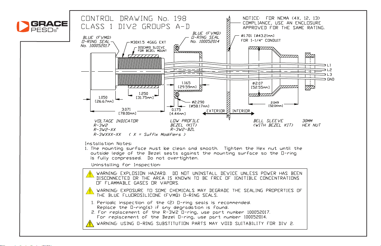
(b) For Low Profile Mount with R-3W2-KB kit, refer to knock-out pattern below and
Control Drawing No. 198 for assembly.
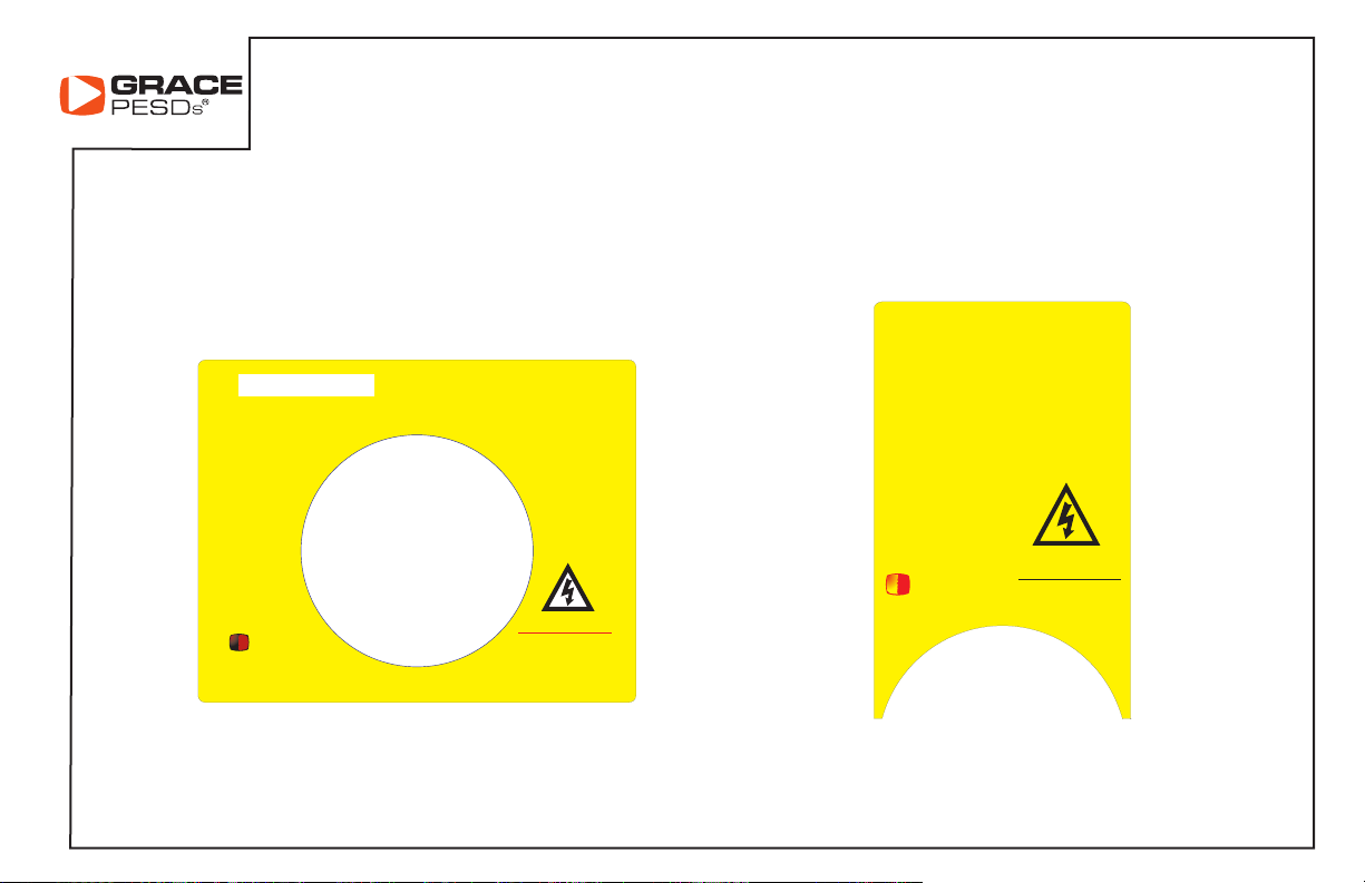
Standard Knockout
*These labels install around the R-3W2 with no affect on its UL certification. The lables are not UL approved.
R-3W2
Low Profile Knockout
Page 3 of 12
5. For Delta configured power, connect the 1 bar, 2 bar & 3 bar black wires to L1, L2, & L3
respectively (Fig. 1) on the fused or disconnect side of the 3-Phase line voltage. The
Green/Yellow stripe (Grn/Yel) wire MUST be connected to Earth Ground. (Fig. 3)
6. Wye configured power with grounded Neutral is connected the same as for Delta in step 5.
The Grn/Yel wire DOES NOT connect to the neutral but to non-current carrying Earth
Ground.
Caution: The neutral will not be monitored for voltage by the Detector, only Phase-to-Phase
and Phase-to-Ground voltage will be detected. To include neutral monitoring go to step 7.
7. Ungrounded or high resistance Wye configured power requires (2) additional units to include
all possible voltages the Neutral line introduces. Wire as shown in Figure 2.
8. Verifying Proper Operation: First disconnect all equipment that may introduce a hazard and
notify personnel before powering the panel!
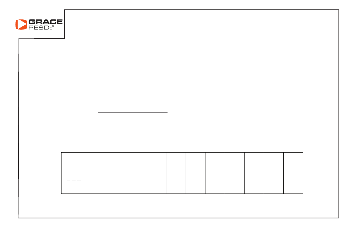
(a) TURN POWER ON. With normal voltage applied, the L1, L2, and L3 indicator pairs
will flash at rates according to the applied voltage (See table below).
INDICATOR FLASH RATES (L1, L2, L3, GND)
3 LINE-TO-LINE (VAC)
~
FLASHES / SEC (TYPICAL)
<29
0 1.3 4.2 5.8 7.3 8.0 8.8
30 120 240 480 600 750
R-3W2
OR STORED ENERGY (VDC)
FLASHES/SEC (TYPICAL)
<27 30 48 110 300 600 1000
0 1.6 2.5 4.5 6.9 8.8 9.1
Page 4 of 12

(Step 8 continued)
(b) GND Indicator Pair Operation: For isolated Delta or 3-Phase WYE applications, it is normal for the “GND”
indicator pairs not to flash unless a phase is lost producing an unbalanced condition. This peculiarity results when
the Phase-to-Phase voltages are balanced resulting in no current to a Neutral connection. The R-3W2 indicators are
current driven; therefore, no net current in the R-3W2 ground line (connected to Neutral) will cause the “GND”
indicators to not flash. A leakage resistance path from any phase-to-ground from 2-7 Meg ohms producing a
corresponding current from 7-67 µA in the “GND” wire is adequate for the “GND” indicators to flash.
To complete proper installation, verify grounding of the GRD lead-wire. Under normal operation, the power
system determines if GRD LEDs illuminates.
Proceed to GRD verification steps below.
1.) Apply power to the R-XXX, if the GRD LEDs do not illuminate, proceed to step 2.)
2.) Remove power and re-establish an electrical safe work condition to allow one phase lead-wire to be
disconnected from its source by either disconnecting wire or pull a fuse.
3.) Re-apply power and verify that the GRD LEDs now illuminate to insure a proper ground connection.
4.) Complete installation by removing power and reconnecting the phase lead-wire or fuse and reapply power and
re-verify that L1, L2, & L3 LEDs illuminate.
BEFORE OPENING A PANEL, TURN POWER OFF! (Steps 1-8 must first verify proper operation of indicators.)
SAFETY PROCEDURES STILL APPLY: Before working on an electrical conductor, verify zero electrical energy with proper
voltage testing instrument and the proper procedure as per NFPA 70E 120.1(5), 120.2 (F)(2)(f)(1-6), OSHA 1910.333(b)(2)(iv)(B).
MAINTENANCE
1. For O-ring inspection, follow the respective Control Drawing directions pages 7 & 8.
2. For cleaning the front blue label or the information sticker, use only clean water and a soft cloth.
R-3W2
For additional information, see Grace Technical Info:
www.pesd.com
Page 5 of 12

R-3W2
Page 6 of 12

R-3W2
Page 7 of 12
R-3W2
Page 8 of 12

Standard Mount Bezel Mount
R-3W2
R-3W2
R-3W2-BZL
Page 9 of 12
DANGER
SAFETY PROCEDURES STILL APPLY.
Many other variations available upon
request. Please call 1-800-280-9517 or visit
VOLTAGE IF ILLUMINATED.
TEST BEFORE TOUCHING.
www.pesd.com
DANGER
VOLTAGE
IF ILLUMINATED.
SAFETY PROCEDURES
STILL APPLY.
BEFORE TOUCHING.
TEST
GRA CE
ENG IN EE R ED
PRODUCTS, INC
WWW.GRACEPORT.COM
Part#: R-3W-L
WARNING!
Read instructions
before installing.
Part#: R-3W-L*
*These labels install around the R-3W2 with no affect on its UL certification. The lables are not UL approved.
R-3W2
GR ACE
ENG I NE ER ED
PRODUCTS, INC
WWW.GRACEPORT.COM
Part#: R-3W-NP-F
Read instructions
Part#: R-3W-NP-F*
WARNING!
before installing
Page 10 of 12

Fig. 2
R-3W2
Page 11 of 12

Fig. 3
Fig. 4
R-3W2 11/2017
Page 12 of 12

 Loading...