

Grace Industries MS900 Series, MS900-H-R-DC, MS900-H-R-AC, MS900-H-R-AC-B, MS900-H-R-AC-B-LS User Information
Page 1

MS900
User Information
MS900-H Systems Equipped with MX900 Micro Receiver will Receive Only.
The MS900 is an AC or DC powered Micro Receiver System designed to receive signaling data
transmissions from Grace Industries’ telemetry products including SuperCELL®, LTX200, and
TPASS®. The MS900 interfaces easily with existing alarm systems and is suitable for use in a fi xed
monitoring location.
Page 2
The MS900 must be mounted in an area where
there is a clear, unobstructed path to the environment where the Transmitting PASS (man-downalarm) or SuperCELL (man-down alarm) may be
used. A typical location for the MS900 would be
near an unobstructed offi ce window or mounted
just outside an offi ce.
The MS900 should also be located as
far away as possible from other radio
equipment antennas to minimize any interference. This includes cell phone boosters, wifi , and
other 2-way radio equipment antennas. It is also
recommended to keep the MS900 a minimum of
six inches away from metal surfaces.
er, the unit may be plugged in. AC power connector
is a screw less Terminal rated for solid or stranded
wire from 14-22AWG. Wire should be stripped at
a 1/2”. Wires should be inserted by using a small
screwdriver to depress the lever and then inserting the wire.
When the unit is plugged in to AC Power, the
AC Power Indicator glows (or fl ashes) Green -
indicating the system has AC Power and is ready
for operation. With loss of power, the AC Power
Indicator glows (or fl ashes) Red - indicating the
Backup-Battery System has been automatically
activated, keeping the MS900 ON and ready for
operation.
The power consumption of the MS900 is low -
typically 100 mA at +12 VDC.
A System Check of the MS900 can be done
by viewing the Receive LED located on the bottom surface of the MS900. When a SuperCELL
or TPASS is turned On, Off, or by activating the
Alarm, the radio signal will cause the Red Receive
LED to fl ash several times - indicating signals are
successfully being received by the MS900.
Once the MS900 has been prepared for AC pow-
12 VDC
MX900H
Battery
Backup
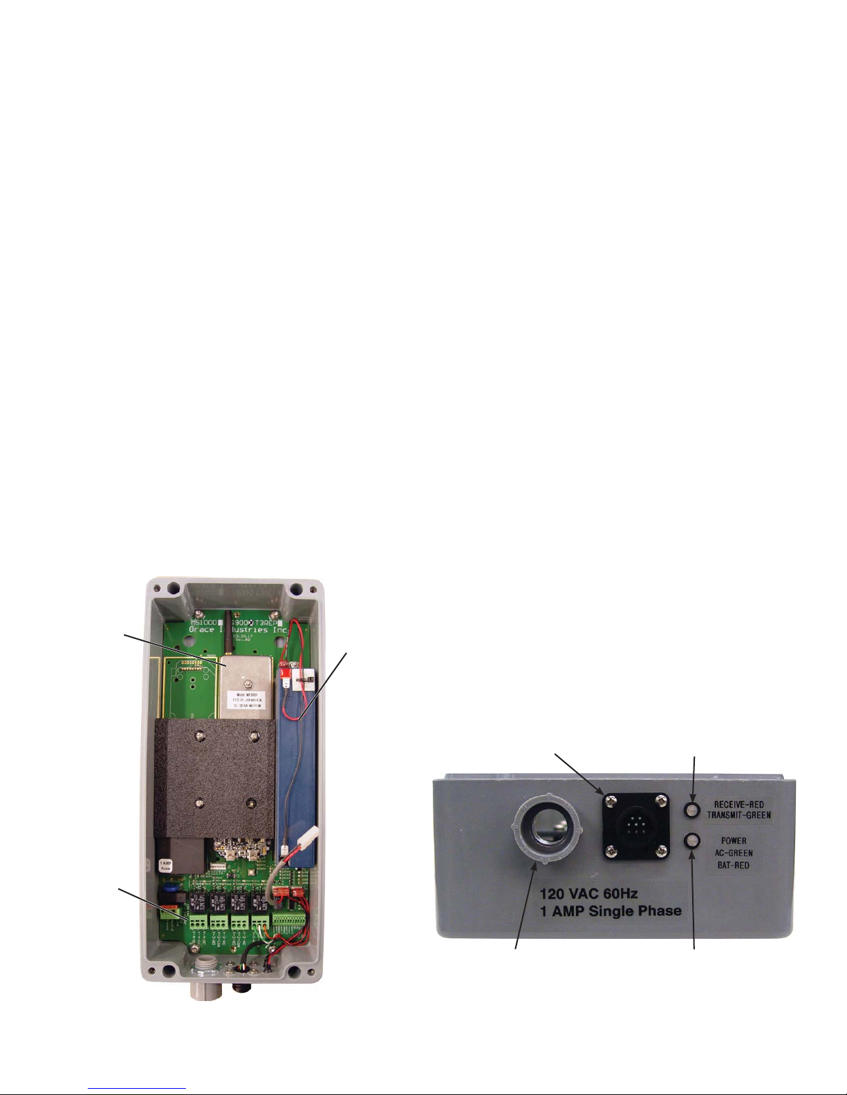
POWER INDICATOR LED
• Green Steady Glow: AC Power and battery is
fully charged.
• Red/Green Alternate Flashing: Battery fault
detected - open or shorted battery.
• Red Steady Glow: Running on battery backup
• Red Flashing: Running on Low Battery.
RECEIVE LED
• Red Flashing: when MS900 is receiving a
triggered message or Reset Acknowledgment.
IMPORTANT:
Always test MS900 and man-down alarms in
area of planned use prior to implementation.
Connector for
Optional
Phone Dialer
Recieve LED
RED: Receiving
Terminal
Blocks
Inside View of MS900
(Shown with MX900H)
Page 2 MS900-H-R 1117
Conduit
Connector
Power LED
GREEN: Running on AC Power
RED: Running on Battery
Page 3

Terminal Block Labeling and Confi guration
A. Power Terminals:
Line
Neutral
GND
B. Relay Terminals:
(4 Sets; Numbered 1 - 4)
Normally Open
Common
Normally Closed
MS900 Factory Default Relay Setting
Relay # Trigger Hold/Activation Time*
1 User Alarm Received 20 Seconds
2 Global Evac Received 20 Seconds
* Hold/Activation Time: How long relay contact will be maintained after
last trigger message is received.
Upgrade Port
A.
Power Terminals
Terminal rated for solid or stranded
wire from 14-22AWG. Wire should
be stripped at a 1/2”.
B.
Relay Terminals
Terminal rated for solid or stranded
wire from 14-22AWG. Wire should
be stripped at a 3/8”.
Inside View of MS900AC-B-LS-D
Additional Notes:
• Except for the battery, all parts of the MS900 are attached to the PCB.
Confi guration Port
Red LED Indicates
Relay is Active
• Connect the AC Power cable to the Line, Neutral, and Ground positions.
• When setting case lid in place, make sure the light siren cable is NOT pinched.
To seal from intrusion of contaminants, secure the case lid by tightening all four (4) lid
bolts until snug.
• Once Installation and Field Testing is complete, the MS900 is ready for use.
Page 3 MS900-H-R 1117
Page 4
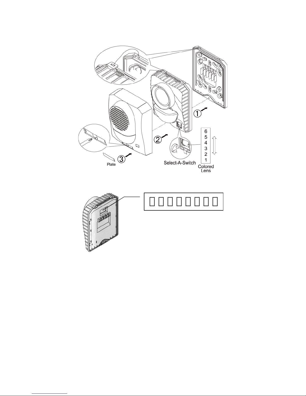
OPTIONAL EQUIPMENT
- Strobe / Siren Settings -
Horn Dipswitch
ON
OFF
1 2 3 4 5 6 7 8
Pattern
1 ON and 2 OFF = Non Temporal
1 OFF and 2 OFF = Temporal
1 ON and 2 ON = March Time
Tone
3 ON and 4 ON = 2400 Hz
3 ON and 4 OFF = Electromechanical
3 OFF and 4 OFF = Chime
3 OFF and 4 ON = Broadband
Volume
5 ON and 6 ON = High
5 ON and 6 OFF = Mid
5 OFF and 6 OFF = Low
7 ON and 8 ON = Horn ON
7 OFF and 8 OFF = Horn OFF
Page 4 MS900-H-R 1117
Page 5

MS900-H-R
Micro Receiver System Specifi cations
Case: Rugged fi berglass
Dimensions: 6-1/2” wide by 15” high by 6-1/2” deep
Weight: 10 lb. (with battery backup and light-siren)
Power Input Requirement:
AC Models: 120 VAC, 60 Hz Single Phase 1Amp
DC Models: 12 VDC ONLY, 0.5 Amp
Battery (Option): 12 VDC, 2.9 Amp. Hr. (provides emergency, backup power for up to 24 hours)
Frequency Range: 902-928 MHz (frequency hopping spread spectrum)
FCC ID: J5MXHEM -- Meets FCC Part 15
IC: 5916A-MXHEM -- Complies with Canadian ICES-003
For Use With: Grace Telemetry Systems using the RadioH platform (SuperCELL SC500, TPASS3,
TPASS5, LTX200, Micro Repeater).
Relay Closure: 4 form-c contact ratings 6A @ 28VDC, 6A @ 125VAC.
MS900-H-R-DC
• Micro-Receiver System, 12 volt DC
• 1 Default Alarm Output Relay 6A-SPDT - 20 second Hold/Activation time.
• 1 Default Global Evac Relay 6A-SPDT - 20 second Hold/Activation time.
• Indoor coverage of 120k sq. feet and 1/2 mile outdoor clear line of site - Indoor Performance is
subject to the effects of building construction and RF noise.
MS900-H-R-AC
• Micro-Receiver System, 120 volt AC
• 1 Default Alarm Output Relay 6A-SPDT - 20 second Hold/Activation time.
• 1 Default Global Evac Relay 6A-SPDT - 20 second Hold/Activation time.
• Indoor coverage of 120k sq. feet and 1/2 mile outdoor clear line of site - Indoor Performance is
subject to the effects of building construction and RF noise.
MS900-H-R-AC-B
• Micro-Receiver System, 120 volt AC, includes battery backup
• 1 Default Alarm Output Relay 6A-SPDT - 20 second Hold/Activation time.
• 1 Default Global Evac Relay 6A-SPDT - 20 second Hold/Activation time.
• Indoor coverage of 120k sq. feet and 1/2 mile outdoor clear line of site - Indoor Performance is
subject to the effects of building construction and RF noise.
MS900-H-R-AC-B-LS
• Micro-Receiver System, 120 volt AC, includes battery backup with light/siren
• 1 Default Alarm Output Relay 6A-SPDT - 20 second Hold/Activation time.
• 1 Default Global Evac Relay 6A-SPDT - 20 second Hold/Activation time.
• Indoor coverage of 120k sq. feet and 1/2 mile outdoor clear line of site - Indoor Performance is
subject to the effects of building construction and RF noise.
Page 5 MS900-H-R 1117
Page 6

OPTIONAL EQUIPMENT
w
- PM2040 Mounting Assembly - Pole Mounted with ‘C’ Brackets -
Bolts and
Bracket Assembly
Bracket
Clamp
Pole
Non-Metallic
Bolt
Toothed
Washer
Flat WasherBracket
MS900
Top View
Pole
Non-Metallic
Page 6 MS900-H-R 1117
Improper Installation May Degrade Performance
Bolts and
Bracket Assembly
S1000
MS900
MS1000
Side View
Side Vie
Side View
Page 7

OPTIONAL EQUIPMENT
CAUTION: To avoid damaging mating pins, carefully match up connector keyways
when attaching phone dialer connector.
Inside View of MS900
Shown with optional 5-Pin Connector
w of MS900
nal 5-Pin Connector
OPTIONAL 10 Foot Cable with Connector
p/n: MS-CA-10
OPTIONAL 5-Pin Connector
p/n: MS-D
OPTIONAL PHONE DIALER
p/n: A TD
MS900 with phone dialer has 5 pin connector
to supply relay contact trigger and power to the
external phone dialer.
Wiring
Pin 1 GREEN Normally Open
PIn 2 WHITE Contact Com.
Pin 3 RED +12VDC
Pin 5 ORANGE Normally Closed
Pin 7 BLACK GND
Page 7 MS900-H-R 1117
Page 8

General Warranty Information
Grace Industries, Inc. warrants Grace Products to be free from defects in workmanship and materials for a period of one
year from the date of purchase. This warranty is valid only when the returned products are accompanied by a sales slip or
other proof of purchase that states the date and location of purchase. Grace Industries, Inc. will not repair or replace any
merchandise under warranty which has been damaged because of accident, misuse or abuse of the products while in possession or control of the consumer. This warranty is void if any attempt to repair or replace parts was made or attempted
by other than qualifi ed Grace Industry’s Inc. personnel. This warranty is void if any of the sealed compartments are opened
or tampered with. Before sending product to Grace for repair, call for Return Authorization or RA #. Please reference RA#
in shipping documents for tracking purposes. Send all repair products, prepaid and accompanied by proof of purchase to:
Grace Industries, Inc., Repair Division, 305 Bend Hill Road, Fredonia, PA 16124. Grace Industries, Inc. shall not be liable
for any direct, incidental or other consequential loss or damage arising out of the failure of the device to operate. End-user
or customer is responsible for return shipping/freight charges.
The sole and exclusive remedy under all guarantees or warranties, expressed or implied, is strictly limited to repair or
replacement as herein provided. All implied warranties, including but not limited to, warranties of fi tness and merchantability,
are hereby limited in duration to a period ending one (1) year from the date of purchase. The warranty and liability set forth
in the prior paragraphs are in lieu of all other warranties, expressed or implied, in law or in fact, including implied warranties
of merchantability and fi tness for a particular purpose. Some states do not allow limitations on how long an implied warranty
lasts, so the above limitations may not apply to you.
This warranty gives you specifi c legal rights and you may also have other rights which may vary from state to state. Tech-
nical assistance is available by contacting Grace Industries, Inc. at 724-962-9231. Product issues may be reported at any
time to Grace Industries, Inc. at 724-962-9231.
FCC Statements
Changes or modifi cations not expressly approved by the party responsible for compliance could void the user’s authority
to operate the equipment.
NOTE: This equipment has been tested and found to comply with the limits for a Class A digital device, pursuant to part
15 of the FCC Rules. These limits are designed to provide reasonable protection against harmful interference when the
equipment is operated in a commercial environment. This equipment generates, uses, and can radiate radio frequency
energy and, if not installed and used in accordance with the instruction manual, may cause harmful interference to radio
communications. Operation of this equipment in a residential area is likely to cause harmful interference in which case the
user will be required to correct the interference at his own expense.
Industry Canada Statements
This Class A digital apparatus complies with Canadian ICES-003.
This device complies with Industry Canada licence-exempt RSS standard(s). Operation is subject to the following two
conditions: (1) this device may not cause interference, and (2) this device must accept any interference, including interference that may cause undesired operation of the device.
Cet appareil numérique de la classe A est conforme à la norme NMB-003 du Canada.(select the class for your device)
Le présent appareil est conforme aux CNR d’Industrie Canada applicables aux appareils radio exempts de licence. L’exploitation est autorisée aux deux conditions suivantes : (1) l’appareil ne doit pas produire de brouillage, et (2) l’utilisateur
de l’appareil doit accepter tout brouillage radioélectrique subi, même si le brouillage est susceptible d’en compromettre le
fonctionnement.
305 Bend Hill Road
Fredonia, PA 16124 U.S.A.
724-962-9231
www.graceindustries.com
© Grace Industries, Inc. Printed in U.S.A.
P/N: MS900-H-R UI 1117
 Loading...