

Grace Industries MS900 Series, MS900-H-R-DC, MS900-H-R-AC, MS900-H-R-AC-B, MS900-H-R-AC-B-LS User Information

MS900
User Information
MS900-H Systems Equipped with MX900 Micro Receiver will Receive Only.
The MS900 is an AC or DC powered Micro Receiver System designed to receive signaling data
transmissions from Grace Industries’ telemetry products including SuperCELL®, LTX200, and
TPASS®. The MS900 interfaces easily with existing alarm systems and is suitable for use in a fi xed
monitoring location.
The MS900 must be mounted in an area where
there is a clear, unobstructed path to the environment where the Transmitting PASS (man-downalarm) or SuperCELL (man-down alarm) may be
used. A typical location for the MS900 would be
near an unobstructed offi ce window or mounted
just outside an offi ce.
The MS900 should also be located as
far away as possible from other radio
equipment antennas to minimize any interference. This includes cell phone boosters, wifi , and
other 2-way radio equipment antennas. It is also
recommended to keep the MS900 a minimum of
six inches away from metal surfaces.
er, the unit may be plugged in. AC power connector
is a screw less Terminal rated for solid or stranded
wire from 14-22AWG. Wire should be stripped at
a 1/2”. Wires should be inserted by using a small
screwdriver to depress the lever and then inserting the wire.
When the unit is plugged in to AC Power, the
AC Power Indicator glows (or fl ashes) Green -
indicating the system has AC Power and is ready
for operation. With loss of power, the AC Power
Indicator glows (or fl ashes) Red - indicating the
Backup-Battery System has been automatically
activated, keeping the MS900 ON and ready for
operation.
The power consumption of the MS900 is low -
typically 100 mA at +12 VDC.
A System Check of the MS900 can be done
by viewing the Receive LED located on the bottom surface of the MS900. When a SuperCELL
or TPASS is turned On, Off, or by activating the
Alarm, the radio signal will cause the Red Receive
LED to fl ash several times - indicating signals are
successfully being received by the MS900.
Once the MS900 has been prepared for AC pow-
12 VDC
MX900H
Battery
Backup
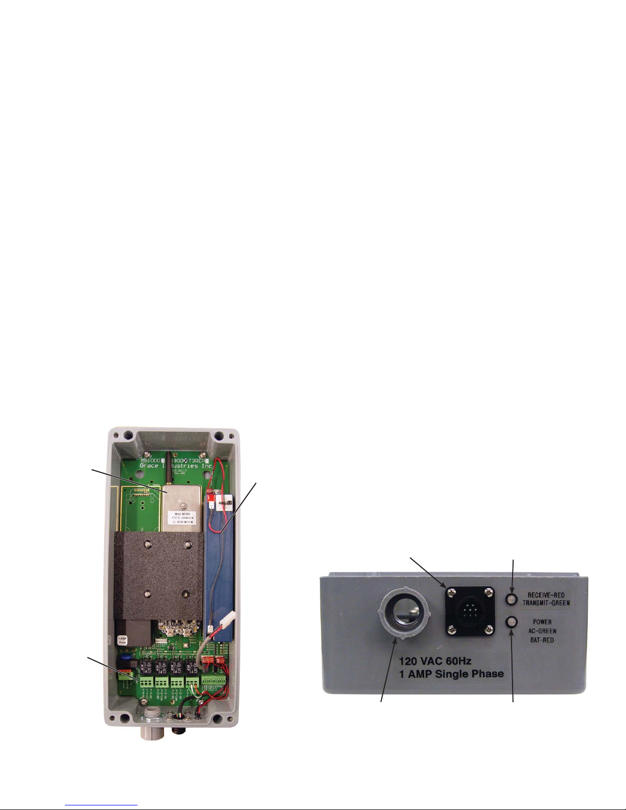
POWER INDICATOR LED
• Green Steady Glow: AC Power and battery is
fully charged.
• Red/Green Alternate Flashing: Battery fault
detected - open or shorted battery.
• Red Steady Glow: Running on battery backup
• Red Flashing: Running on Low Battery.
RECEIVE LED
• Red Flashing: when MS900 is receiving a
triggered message or Reset Acknowledgment.
IMPORTANT:
Always test MS900 and man-down alarms in
area of planned use prior to implementation.
Connector for
Optional
Phone Dialer
Recieve LED
RED: Receiving
Terminal
Blocks
Inside View of MS900
(Shown with MX900H)
Page 2 MS900-H-R 1117
Conduit
Connector
Power LED
GREEN: Running on AC Power
RED: Running on Battery
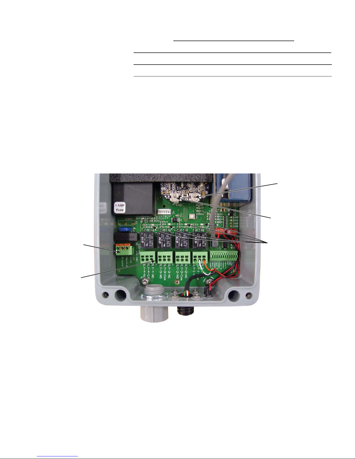
Terminal Block Labeling and Confi guration
A. Power Terminals:
Line
Neutral
GND
B. Relay Terminals:
(4 Sets; Numbered 1 - 4)
Normally Open
Common
Normally Closed
MS900 Factory Default Relay Setting
Relay # Trigger Hold/Activation Time*
1 User Alarm Received 20 Seconds
2 Global Evac Received 20 Seconds
* Hold/Activation Time: How long relay contact will be maintained after
last trigger message is received.
Upgrade Port
A.
Power Terminals
Terminal rated for solid or stranded
wire from 14-22AWG. Wire should
be stripped at a 1/2”.
B.
Relay Terminals
Terminal rated for solid or stranded
wire from 14-22AWG. Wire should
be stripped at a 3/8”.
Inside View of MS900AC-B-LS-D
Additional Notes:
• Except for the battery, all parts of the MS900 are attached to the PCB.
Confi guration Port
Red LED Indicates
Relay is Active
• Connect the AC Power cable to the Line, Neutral, and Ground positions.
• When setting case lid in place, make sure the light siren cable is NOT pinched.
To seal from intrusion of contaminants, secure the case lid by tightening all four (4) lid
bolts until snug.
• Once Installation and Field Testing is complete, the MS900 is ready for use.
Page 3 MS900-H-R 1117
 Loading...