

Page 1

Instrument Preamplifier / EQ / DI
Owner’s Manual Rev. B
Grace Design, 4689 Ute Highway, Lyons, CO 80503
303.823.8100 / info@gracedesign.com
www.gracedesign.com
Page 2
1 Welcome
Like its big brother FELiX, the ALiX you hold in your hand is
designed to make you sound better, play better and have more
fun in the process. From Banjo, bass to bouzouki, if it has strings
and a pickup, ALiX will make its tone shine through.
While ALiX is not the most complicated piece of gear you’ve
ever operated, it does aord a good bit of exibility and setup
options, which means we highly recommend you have a good
look at this owner’s manual to familiarize yourself with its
ner points. Once you overcome the learning curve (easy, we
promise), you’ll nd AliX to be intuitive and user friendly.
TABLE OF CONTENTS
1 Welcome 2
2 Safety Information 2
3 Safety Marking Symbols 3
4 Features 3
5 Top Panel Controls and Features 4
6 Back Panel Controls and Features 5
7 Side Panel Controls and Features 5
8 Connecting ALiX to Stu 6
8.1 1/4” Instrument input 6
8.2 Insert (FX LOOP) 6
8.3 Amp Out 6
8.4 Tuner Output 6
8.5 DI Output 6
8.6 100-240VAC Power Input 6
8.7 9V @ 500mA DC POWER OUTPUT 6
9 Operation 6
9.1 Where to put ALiX? 6
9.2 Instrument / line input 6
It is our sincere hope that our gear helps you do better work.
You are why we do this. Please drop us a line or a message and
let us know what you think.
And by all means if you ever have any questions about using
your ALiX or anything else we make, call us at 1-303-823-8100,
9-5 MST.
Have fun!
- The Grace Design Team
9.3 Filtering and EQ 7
9.4 Output controls 8
9.5 Footswitch Controls 8
9.6 Side Panel Controls 8
10 Diagrams 9
10.1 Insert cable Wiring 9
10.2 Block Diagram 10
10.3 Connection Diagram 11
10.4 AdJusting Internal Jumpers 12
10.5 Internal Jumper Locations 13
11 Specications 14
12 Cleaning and Maintenance 15
13 Warranty 15
14 Manual Revisions 16
2 Safety Information
• Indoor use only
• Ordinary Protection: This equipment should not be
exposed to dripping or splashing.
• Avoid placing objects lled with liquids, such as vases or
glasses, on this equipment.
• Class I Equipment (grounded type)
• Electrical rating: 100-240V~ 50-60Hz 10W
• Mains supply voltage uctuations are not to exceed ±10%
of the nominal supply voltage.
• Pollution Degree 2
• Installation (Over voltage) Category II for transient
2
overvoltages.
• Maximum Relative Humidity: <80%
• Operation temperature range: 10 °C to 40 °C
• Storage and transportation temperature
range –40 °C to 70 °C
• Maximum altitude: 3000m (9843 ft)
• Equipment suitable for continuous operation
• Weight: 2.2lbs
Page 3

3 Safety Marking Symbols
Caution: Read Accompanying Documents
This symbol, located on the equipment and in
this manual, refers to important instructions.
Read this manual thoroughly before operating
this equipment.
Warning: Electrical Shock Hazard
This symbol, located on the equipment and in
this manual, indicates the potential for electrical
shock hazard.
4 Features
• Open, musical and detailed instrument preamplication for
discerning artists and engineers like yourself
• Ultra precision 0.5% thin lm resistors used in the signal
path
• Careful power supply design and grounding for an ultraquiet signal path and professional level headroom and line
driving ability
Service Information
The Grace Design ALiX contains no user serviceable
components. Contact Grace Design for repair and upgrade
information. In the event that your Grace Design Felix needs to
be returned to the factory, contact us for a return authorization
number.
power output for powering other pedals from the ALiX
• Boost footswitch for variable 10dB level boost
• Dedicated level controlled stage amp output
• Dedicated tuner out, remains active when unit is muted
• Side panel switches for mid Hz range select, HPF/notch
select, 12V microphone power enable
• Fully ground isolated DI output with high quality, low
distortion, fully shielded transformer
• Super rugged 1/4” connectors with heavy duty metal
bushings
• Powerful, independent EQ – hi and low shelving and full
parametric midrange
• Mid frequency control has two ranges 70-880Hz / 670 8kHz
• 20Hz-1kHz sweepable HPF on both channels, can also be
set as notch lter
• Mute/ tune footswitch mutes all outputs except dedicated
tuner out and headphone output
• 12V mic input power
• 9VDC @ 500mA (2.1mm BOSS™ standard center negative)
• Phase reverse switch
• 3 input impedance settings – 330KΩ, 1MEGΩ, 10MEGΩ
accommodating a wide range of pickup types
• TRS eects insert jack
• Universal 100-240 AC power supply with standard IEC
cable – no wall wart - take ALiX anywhere in the world!
• Full 5 year transferable warranty / built for a long, happy
life on the road
• Designed and built by us in Lyons, CO, USA
3
Page 4
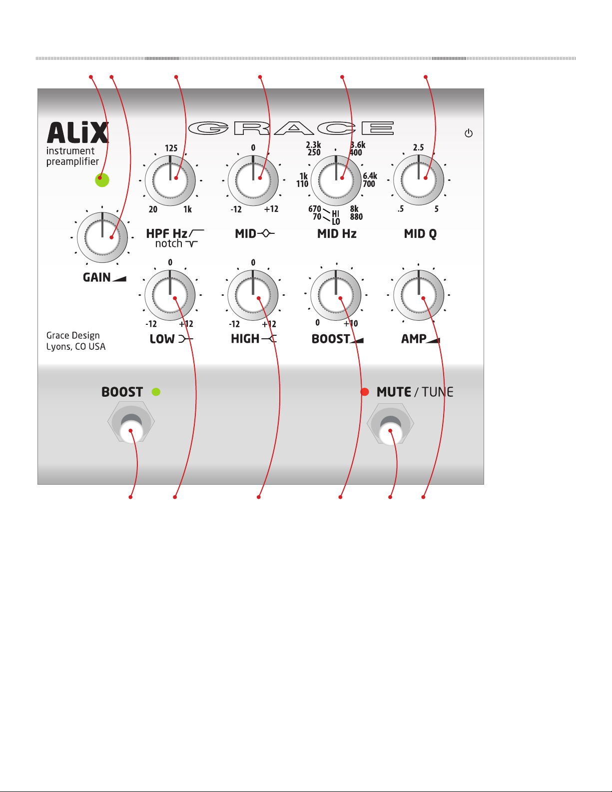
5 Top Panel Controls and Features
1 2 3 4
5 6
7 8
1. Signal / clip LED indicator
2. Gain control
3. High Pass / Notch lter frequency select
4. Parametric Midrange cut and boost
5. Parametric Midrange frequency select
6. Parametric Midrange Q factor
7. BOOST footswitch
8. Low frequency shelving cut and boost
9. High frequency shelving cut and boost
10. Boost level
11. MUTE / TUNE footswitch
12. Amp / Tuner output level
4
9 11 12
10
Page 5
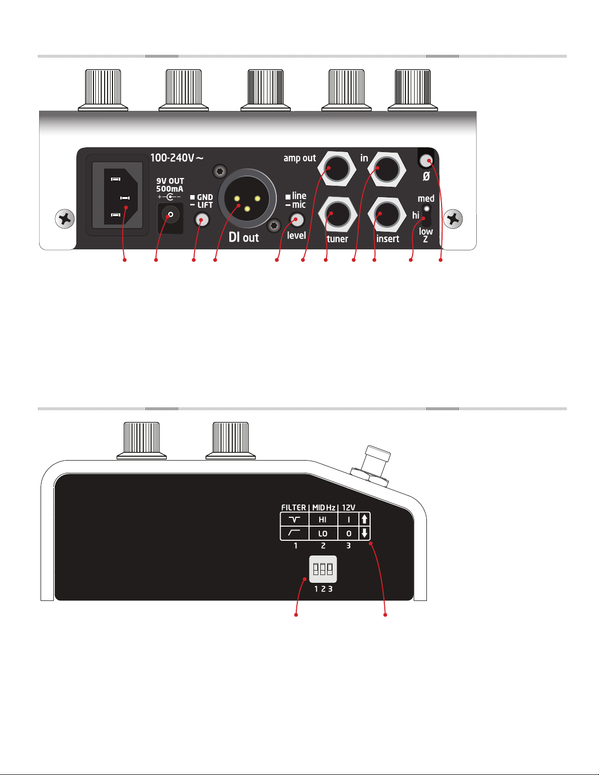
6 Back Panel Controls and Features
1 2 3 4 95 6 7 8 10 11
1. Universal input100-240VAC power supply input module
2. 9VDC @ 500mA auxiliary power output
3. Ground lift switch
4. DI output
5. DI output line / mic level select
7. Tuner Output
8. Instrument line input
9. Eects Insert
10. Input impedance select
11. Phase reverse switch
6. Amp Output
7 Side Panel Controls and Features
1 2
1. DIP switch controls:
1) HPF or Notch select
2) MID EQ range LO or HI
3) 12V power on and o
2. Dip Switch location diagram
5
Page 6

8 Connecting ALiX to Stuff
8.1 1/4” INSTRUMENT INPUT
This is for connecting any instrument with a pickup, electret
mic or line out jack to ALIX. The connector is a standard 1/4”
jack wired tip signal, sleeve ground. The ring is used only for
12V mic power if needed.
8.2 INSERT (FX LOOP)
The insert connection is a buered, unbalanced insert point
(pre boost) for connecting outboard eects to ALiX. This allows
mono outboard signal processing to be placed in series with
the signal, while still utilizing all of ALiX’s output capabilities.
It is a 1/4” TRS connection, wired tip to send, ring to return
and sleeve to ground. The insert send has an adjustable pad if
you are using an eect pedal with lower headroom. The pad
has 3 settings (o, -6dB and -16dB) that can be set via internal
jumpers.
SEE JUMPER DIAGRAM page 13
8.3 AMP OUT
This output is for sending an unbalanced, non-transformer
isolated output to a stage amp or anywhere else you may need
an additional unbalanced signal. This output has the added
benet of a level control, which is situated on the right side,
bottom row of controls on the top panel. This output is muted
when the MUTE / tune footswitch is activated.
8.4 TUNER OUTPUT
This is another unbalanced output which is always active –
provided as a dedicated stage tuner out. When the MUTE is
activated, your stage tuner will continue to receive signal,
allowing you to tune silently. The tuner output level follows the
Amp Out level control.
8.5 DI OUTPUT
This outputs is a balanced and transformer isolated, for sending
signal to a front of house, monitor console, or any mixer or
interface where balanced, isolated signal needs to be sent. XLR
pinout is: pin 2 positive, pin 3 negative and pin 1 ground.
This output has an adjacent level setting switch – line and mic,
depending on what input this source will be feeding. In the
‘mic’ setting, the output is padded down -26dB to interface
properly with mic inputs at the console, the ‘line’ setting is not
padded for better level matching with line level inputs at the
console or interface.
8.6 100-240VAC POWER INPUT
ALiX is powered by a universal AC power supply. This means
that no matter where your musical wanderings take you, ALiX
can plug into the wall and it will work. And it also means one
less wall wart you’ll own in your life. All units are shipped with
a standard AC cable suitable for the country where it is going.
This is a standard, o-the-shelf IEC power cable, so in the event
you misplace the one that came with your ALiX, you can just
borrow one from the soundperson and go. Tell them we said so.
8.7 9V @ 500mA DC POWER OUTPUT
This output jack will power other 9VDC pedals you may have
at your feet. The jack is a standard 2.1mm BOSS™ style, with
the center negative. Maximum output current is 500mA, which
means you need to add up the current draw of all the pedals
you wish to power to ensure they don't exceed that. To connect
multiple pedals, you'll need an o the shelf multi-plug daisy
chain cable.
9 Operation
9.1 WHERE TO PUT ALIX?
Great question. We recommend you put it wherever you want.
It will look very pretty when you rst pull it out of his box, but
trust us, it's built to stand up to just about any kind of stage
shenanigans you might encounter. All the pots have metal
shafts and are well mounted to the top panel. All the 1/4” jacks
have heavy duty metal bushings. The top panel is 1/4” extruded
aluminum, and the bottom chassis is appropriately heavy duty.
As you may have surmised by now, the main inspiration for this
product was to have studio-grade audio hardware, properly
ruggedized to live on the stage oor or mounted to a pedal
board. Velcro is ne. The installed rubber feet will thread out so
your Velcro mount will be ush. Hang on to those rubber feet,
though, they're pretty nice.
9.2 INSTRUMENT / LINE INPUT
This is the input you will use for connecting your instrument
to ALiX. There is a wide array of dierent pickup types in the
6
world: active electronics in an electric bass, passive under
bridge plate transducers, contact mics, soundhole magnetics,
etc..
Setting the Gain
The rst control on the left side of the top panel is the GAIN
control. With your instrument connected to the input and
signal owing, turn the GAIN knob clockwise until the signal /
clip LED indicator is on and lit solid green. This will represent a
good operating level. The indicator will start to ash red when
your signal is 13dB before clipping, so occasional red ash is ok,
but mostly red means you should turn the gain control down /
counterclockwise.
Input Impedance Selection
The instrument input has 3 dierent impedance settings:
med - 1MΩ / hi -10MΩ / low – 330kΩ
In general, most passive pickups will want to connect to a
Page 7

higher impedance setting, while active pickups probably a
lower. Passive pickups generally will have more sensitivity to
input impedance, but there are no hard and fast rules. Check
with the manufacturer of your particular pickup system to see
if they recommend a specic input impedance for their device.
Ultimately, as is with so many things like this, the nal judge
of this setting should be your ears. Impedance mismatches at
this stage may not even be audible, or very subtle, or totally
apparent. But trust yourself here – nothing will break if you
have the wrong setting – just audition the 3 positions of the
impedance switch and if one sounds better over the other 2,
then that’s the correct setting.
Phase Reverse
ALiX has a phase reverse switch, located on the rear panel, top
right (facing the rearpanel), directly above the input impedance
switch. Use this to toggle the polarity of audio signal.
Phase relationships can be very complicated, and discrepancies
can result in highly accentuated or de-accentuated bass
response of an out of phase signal. Or it can sound hollowed
out and thin, or just downright weird. Again, the rule of thumb
here is whatever sounds right is probably right.
There may be setup scenarios where the front of house or
monitor engineer requires you to try ipping the phase to
achieve better phase coherency with other signals in the mix.
At the very least, it’s good for you to know how to operate this
controls and hear it in use with your instrument.
rumble or non-musical low frequency information out of a
signal. But this HPF range is from 20Hz to 1.0kHz, so you can
make very dramatic lter settings.
Some instruments won’t have any information below a
certain frequency. Fiddle for example only extends its lowest
fundamental down to 200Hz. So if you are amplifying a ddle,
you could safely set the HPF at 150 – 200 Hz without hearing
much eect in the tonality of the instrument. Whereas a bass
can have a low fundamental down around 30Hz, so setting the
HPF any higher than that could aect its tonality.
If you are on a stage with an acoustic guitar, and there is lots of
low end making you sound bad, or feeding back or both, the
HPF might be your rst stop to try to control those problems.
Notch: A notch lter is a very sharp and deep cut of a specic
frequency. This is used predominantly to nd and remove a
specic problem frequency that may be feeding back through
stage monitors or amps, or to simply cut out a very specic,
narrow unwanted part of an instrument’s frequency range. This
notch uses the same frequency sweep range of 20Hz – 1.0kHz.
GAIN
0dB
-12dB
40 125 20k1k
NOTCH FILTER
Hz
9.3 FILTERING AND EQ
One of the dening features of our ALiX is the very powerful,
EQ / lter controls. If you haven’t used EQ’s or lters much,
we will provide a basic overview here. But the full science of
this process is more than we can cover here, so we strongly
recommend some adjunct reading:
http://en.wikipedia.org/wiki/Equalization
As with all audio processing techniques, the more you know,
the better you will sound.
HPF / Notch
This is the upper control to the right of the GAIN knob. To
select between HPF and Notch, adjust the left side DIP switch
locations # 1.
HPF: A High Pass Filter will only allow signal information above
its set frequency to pass downstream to the output. This
lter employs 12dB per octave roll o and uses a Thomson –
Butterworth response for the best combination of passband
atness and time domain response. Yes, that will be on the quiz.
GAIN
0dB
-12dB
Simply put, use the high pass lter to cut unwanted bass
frequencies out of a signal. Usually a HPF is used to eliminate
40 125 20k1k
HIGH PASS FILTER
Hz
Parametric Mid Controls
The mid range section of ALiX’s equalizer is fully parametric,
which enables you control the mid range gain, frequency and Q
independently. The range of these controls are:
Gain = +/- 12dB,
Freq range LO setting = 70Hz – 880Hz
Freq range HI setting = 670Hz – 8.0kHz
Q = .5 – 5
The frequency range can be switched between the LO and
HI settings via the left side panel DIP switch locations # 2.
With these two available ranges, the over all range of the mid
controls is very wide, which enables targeting of specic sonic
areas of a multitude of instrument or pickup types.
0dB
MID EQ
20
Q
1k
20k
Hz
GAIN
+12dB
-12dB
Q factor determines the sharpness of the bandwidth of the
frequency being adjusted. A higher Q factor setting – turning
the Q knob further clockwise - creates a sharper bandwidth
and thus a more targeted, surgical EQ adjustment. Alternately,
a lower Q factor - turning the Q knob further counter clockwise
- creates a broader tonal adjustment.
Low Control
7
Page 8

The Low control of the ALiX preamplier is xed at 125Hz
corner frequency / 40Hz peak, with a gain range of -12 to
+12dB. This is a xed shelving type control, which means
everything below the 125Hz is boosted or cut. Use this control
for cutting and boosting bass frequencies. It’s all about the
bass.
GAIN
+12dB
0dB
LOW SHELF EQ
might easily send you in to feedback territory. So start small.
If you need to boost your output, start with a gentle boost
amount and work your way upwards. If you start to hear stage
feedback or are overloading the input at the console, then
you’ll need to back it o.
ALiX is not responsible for disgruntled soundpeople you may
encounter during the operation of the boost circuit, especially
those you have already borrowed your misplaced IEC power
cable from. Keep those people happy, they control the suck
knob.
-12dB
40 125 20k12k
Also, because certain acoustic instruments (banjo, ddle,
plinkly little whathaveyous) may react better to a higher corner
/ peak frequency, we have added a Low control range jumper
on the main PCB. Moving this jumper shifts the Low frequency
up to 250Hz (+/-3dB) corner frequency / 80Hz peak. This is easy
to do! We specically designed ALiX’s chassis to make it easy to
access internal jumpers. Please refer to the jumper diagram and
access procedure on pages 12 and 13. Bravo to you for reading
this manual. You get an A.
WARNING Make sure to disconnect the power mains
before opening removing the ALiX top panel to
make jumper adjustments.
Hz
High Control
The High control of the ALiX preamplier is set with a 2kHz
(+/-3dB) corner frequency/ 12kHz peak, with a gain range of
-12 to +12dB. This is a xed shelving type control, which means
everything above the 2kHz is boosted or cut. Simply put, this is
a treble control. If you think your banjo may be too bright, turn
this knob counterclockwise. If you think your guitar needs a
little more bite, turn this knob clockwise. If you’re not sure, then
get down there and start turning it one way or the other until it
sounds better.
GAIN
+12dB
0dB
-12dB
20
HIGH SHELF EQ
2.0k
Hz
20k12k
9.4 OUTPUT CONTROLS
Boost
Want ALiX to go to eleven? How about twenty? This knob
sets the amount your signal is boosted when you activate
the ‘BOOST’ footswitch. Fully counter-clockwise is zero boost
added, fully clockwise adds +10dB of boost. The boost is after
the FX loop and aects both the DI and amp outputs.
As you can probably imagine, if you are using a microphone
or a particularly feedback prone pickup system, adding boost
Amp Output Level
This knob sets the output level of the unbalanced Amp and
tuner outputs on the rearpanel. If you are using a stage amp,
use this control as your master level. Correct input gain settings
for your sources, with the signal LED showing mostly green,
should not be adjusted to alter your stage amp level. Rather,
use this control to make master level changes.
Troubleshooting advice: if you stage tuner is connected to the
'tuner' jack but not working, make sure your Amp out knob is
turned up suciently.
9.5 FOOTSWITCH CONTROLS
Boost
You guessed it. This switch activates the Boost circuit, at
whatever level you set with the boost knob. This circuit is
global, so the boosted signal will be coming out of every
output. For those about to rock, you'll need to activate this
switch rst before we can solute you. The LED will light up
GREEN for go.
Mute / Tune
This switch mutes the DI and AMP output, but not the tuner
output. This enables you to quickly and easily cut your signal
to the FOH or stage amp and tune or unplug your instrument
without having to have the soundperson mute your channel.
When MUTE / tune is active, the adjacent LED illuminates RED.
9.6 SIDE PANEL CONTROLS
ALiX has a lot going on, more than we could t on the rear and
top panels alone. So there are a few features to be familiar with
on the side panel.
DIP Switches
This is a bank of 3 DIP switches, used to activate various modes
or settings. Switch 1 selects between the HPF or notch setting.
Switch 3 selects between the mid EQ’s frequency range, LO or
HI. Switch 3 activates 12V power on the instrument input.
DIP switches are hard to adjust, which is good because they
probably won’t get inadvertently changed, but bad when you
actually want to change them. Use the edge of a ngernail, a
guitar pic or a toothpick. Whatever you chose, take care not to
dig into the plastic too hard. You’ll get the hang of it.
8
Page 9

12V Power
GND
1/4" TRS PLUG
TIP
SLEEVE
To Felix Insert Jack
SEND
RETURN
1/4" TS PLUG
1/4" TS PLUG
To Outboard Input Jack
To Outboard Output Jack
GND
RING
The instrument input can be used to amplify an electret
capacitor microphone. These are common for applications
where a small microphone is mounted inside acoustic
instruments, or lavalier style microphone used somewhere on
the outside of the instrument. Normally these microphones will
contain very small integrated preamps which require a voltage
to power. So the ALiX can send 12V phantom power out on this
input. This is activated via DIP switch # 3 on the side panel.
10 Diagrams
10.1 INSERT CABLE WIRING
12V power can be applied to the tip or ring of the instrument
input jack. Conguration is done via internal jumpers,
described in detail on pages 12 & 13.
NOTE: this power supply charges up slowly, so you may need
to wait a few seconds before signal from your electret mic is
present at the input of ALiX. It is always best to make your input
connections before applying power at the DIP switch, and power
OFF the 12V at the DIP switch before disconnecting your source.
9
Page 10

10.2 BLOCK DIAGRAM
INSERT RETURN
INSERT SEND
0, -6dB, -12dB
INSERT SEND PAD
GROUND LIFT
ISO BALANCED OUT
MUTE / TUNE
ISO MIC / LINE LEVEL
BOOST GAIN
BOOST ON/OFF
AMP OUTPUT LEVEL
ISO OUTPUT TRANSFORMER
AMP UNBALANCED OUT
TUNER UNBALANCED OUT
MONO HEADPHONE OUT
VIA JUMPER
EXT. BOOST FSW ENABLE
EXTERNAL FOOTSWITCH INPUT
TIP
RING
MUTE / TUNE
BOOST ON/OFF
9V 2.1mm CENTER = NEG OUTPUT
9V @ 300mA
POWER SUPPLY
HIGH FREQ
BOOST / CUT
Q
MID FREQ
MID FREQ
FREQ SEL
MID FREQ
BOOST / CUT
LO/HI RANGE
FRONT PANEL KNOB
SIDE PANEL DIP SWITCH
REAR PANEL PUSHBUTTON SWITCH
REAR PANEL TOGGLE SWITCH
INTERNAL JUMPER SETTING
FOOTSWITCH
CONTROL TYPES:
LOW FREQ
BOOST / CUT
SEL
FREQ SEL
HPF / NOTCH
HPF / NOTCH
POLARITY
GAIN
INPUT
IMPEDANCE
SIG / CLIP INDICATOR
10
+12V MIC POWER
(TIP / RING / OFF) VIA JUMPER
+12V ON/OFF
1/4" UNBALANCED INST IN
Page 11

10.3 CONNECTION DIAGRAM
Your instrument plugs into ALiX
Mr. Amp
9VDC OUT
powers a
few pedals
A
out input
out input
reverb
tuner
stage amp is fed by amp out
through the insert
external eects are routed
stage tuner is
fed by tuner out
Nothing too terribly hard and fast here - just the basics about how to plug stu in and out of your
preamp. INPUT paths are shown in blue. OUTPUT paths are shown in red.
ALiX connections
There are many ways to setup your preamp, so if you aren’t sure about how something works, please
have a look at your owner’s manual, check out our website - www.gracedesign.com - or feel free to
call us. We are always glad to help out in any way we can. 1.303.823.8100, M-F, 9-5 MST
PA system / mixer is fed by DI output
100 ~ 240 VAC power
11
Page 12

10.4 ADJUSTING INTERNAL JUMPERS
Several ALiX settings can be adjusted via internal
jumpers. While it’s not trivial to do, if you are handy with
a screwdriver and tweezers, you’ll be ne. This is not
something you should attempt to do on a dark stage or in
the back of the tour van. Directions for disassembling the
chassis and accessing the jumpers is as follows:
IMPORTANT: Before you do anything, disconnect ALiX
from the AC power, disconnect all cables and place ALiX
on a at stable surface with good lighting.
1. DOUBLE CHECK: Did you completely disconnect the
power supply? Ok then.
2. With a #2 phillips screwdriver, remove the 4 chassis screws,
located on the outer edges of the front bottom and rear
bottom of the aluminum top chassis (gure 1) .
3. Orient the unit so the rearpanel is facing forward towards
you. Carefully pull up on the top chassis and ip it up
and over the bottom chassis (gure 2). This will reveal the
top and bottom circuit boards. Do not pull them apart
any further than the ribbon cables that connect them
will allow. The top should rest easily on the work surface
ipped over and behind the bottom chassis (gure 3).
4. Now refer to the jumper location diagram on the following
page to move any jumpers you wish (closeup - gure 4).
gure 1
gure 2
5. To move a jumper, use tweezers or your ngernails to
gently pull the jumper o of its header pins. To reposition
the jumper, double check the diagram, then gently press
the jumper back down in the correct location.
6. J10 resides on a 2-pin header. If you wish to set this to
a non-jumpered setting, simply push one side of the
jumper down onto one pin, so that the two pins are not
connected.
7. When you are nished adjusting the jumpers, make sure
there are no loose jumpers or any other junk lying around
inside your ALiX.
8. Then carefully reassemble the top and bottom chassis,
making sure to let the ribbon cable fold easily back in
place. If there is any tension or something isn’t tting
properly, carefully pull the top and bottom back apart and
inspect for interference.
9. Once you have put the unit back together, replace the 4
screws, making sure they go in straight and true. You may
need to nudge the top panel back and forth a bit to ensure
the holes in the top panel chassis line up evenly with the
inner threaded holes.
10. Do not tighten the screws until all 4 are cleanly started in
the threads. Take your time and remember, cross-threading
is a crime.
gure 3
gure 4
12
Page 13

10.5 INTERNAL JUMPER LOCATIONS
J10 congures the LOW
EQ corner frequency. It is
set to LF1 at the factory
(125Hz corner frequency)
with the jumper
connecting the 2 pins.
To set to LF2 (250Hz
corner frequency), simply
push one side of the
jumper down onto one
pin, so that the two pins
are not connected.
J2
J6
J6 sets the pad settings
for the INSERT send.
Levels are -6dB, -16dB,
or o. Set to o at the
factory
J2 congures 12V power,
which can be applied
to tip, ring, or set to o.
Set these according to
how your microphone /
instrument is wired. Set
to o at the factory
13
Page 14

11 Specifications
GAIN RANGE (Instrument Input to DI Output)
DI Output, Level: Line -2dB - 36dB
Amp Output 0dB-39dB
Boost 0dB-10dB
THD+N 22Hz-22kHz BW
1kHz @ 0dB Gain +10dBu out <0.0070%
1kHz @ 20dB Gain +10dBu out <0.0045%
1kHz @ 36dB Gain +10dBu out <0.0080%
INTERMODULATION DISTORTION - SMPTE/DIN 4:1 7kHz/50Hz
@ 40dB Gain +10dBu out <0.05%
FREQUENCY RESPONSE
Inst input @ 20dB Gain -3dB 20Hz – 65kHz
I/O IMPEDANCE
Instrument Input HI: 10MΩ / MED: 1MΩ / LOW: 330kΩ
Insert Input 10kΩ
Insert Output, No Pad 750Ω
Insert Output, -6dB Pad 375Ω
Insert Output, -16dB Pad 122Ω
DI Output 150Ω
Amp Output 150Ω
Tuner Output 150Ω
SIGNAL / PEAK LED METER
Green threshold -16dBu
Red threshold +8dBu
MAXIMUM INPUT LEVEL
Instrument Input +20dBu
Insert Return (0dB Boost) +20dBu
MAXIMUM OUTPUT LEVEL - 100k Ohm load, 0.1% THD
DI Output (Line) +19dBu
DI Output (Mic) -7dBu
Amp, Tuner, Insert Outputs +21dBu
Insert Output, No Pad +21dBu
Insert Output, -6dB Pad +15dBu
Insert Output, -16dB Pad +5dBu
HIGH PASS FILTER / NOTCH FILTER
High Pass Filter 20Hz – 1kHz @ -12dB/octave
Notch Filter 20Hz – 1kHz, >-35dB, Q>1.0
EQ
Gain +/- 12dB
Low Frequency Low Range: 125Hz Shelving / High Range: 250Hz Shelving
Mid Frequency Low Range: 70Hz – 880Hz / High Range: 670Hz – 8kHz
Mid Frequency Q 0.5 – 5
High Frequency 2kHz Shelving
DYNAMIC RANGE 22Hz-22kHz BW
Minimum Gain, DI Out 118dB
OUTPUT NOISE 22Hz-22kHz BW
Minimum Gain, DI Output -99dBu
Minimum Gain, Amp Out -96dBu
Maximun Gain, DI Out -77dBu
Maximum Gain, Amo Out -74dBu
POWER CONSUMPTION
100-240VAC 50/60Hz 10 Watts Max
POWER OUTPUT
2.1mm BOSS™ style power jack, center negative 9VDC, 500mA Max
WEIGHT and DIMENSIONS
2.2lbs (1kg) H3.0” x W6.2” x D5.5” (H7.6cm x W15.7cm x D14.0cm)
14
Page 15

12 Cleaning and Maintenance
Your ALiX is chassis is constructed out of high quality aluminum and steel. Under normal circumstances, very little maintenance is
required to keep it looking good. However, if you nd it getting more dirty or dusty than you like, here are some cleaning tips: We
recommend using a little shot of Windex™, applied to a clean, dry, lint free cloth. Gently wipe all surfaces, taking care not to allow
the cleaning product to build up around or under the knobs.
13 Warranty
• Grace Design warrants this product to be free of defective parts and workmanship for a period of ve years. This warranty
period begins at the original date of purchase and is transferable to any person who may subsequently purchase the product
during this time.
• This warranty excludes the following conditions: normal wear and tear, misuse, customer negligence, accidental damage,
unauthorized repair or modication, cosmetic damage and damage incurred during shipment.
• During the time of this warranty, Grace Design will repair or replace, at its option, any defective parts or repair defective
workmanship without charge, provided the customer has appropriate proof of purchase and that the product has its original
factory serial number.
• In order for Grace Design to provide ecient and timely warranty service, it is important that you mail the completed
warranty registration card enclosed with all of our products within 10 days of the original date of purchase. You may also
register your product directly with Grace Design by telephone (303-823-8100 Monday-Friday 9:00am to 5:00pm MST), or you
can register your product online at www.gracedesign.com.
• This warranty is in lieu of all other warranties whether written, expressed, or implied, INCLUDING ANY WARRANTIES OF
MERCHANTABILITY OR FITNESS FOR A PARTICULAR PURPOSE.
• In no event will Grace Design be liable for lost prots or any other incidental, consequential or Exemplary damages, even if
Grace Design is aware of the possibility of such damages. In no event will Grace Design’s liability exceed the purchase price of
the product.
• This warranty gives the customer specic legal rights. The customer may also have other rights, which vary from state to state.
Some states do not allow limitations on implied warranties or consequential damages, so some of the limitations of the above
may not apply to a particular customer.
15
Page 16

14 Manual Revisions
Revision Page Change Date Initials
A all Initial release 06/08/2016 edg
B 3,6,14 Added info about 9V 500mA DC power output jack 07/08/2016 edg
B 3,6,14 Corrected input impedance values 7/11/2015 edg
16
 Loading...