

Grace Company Sure Stitch User Manual
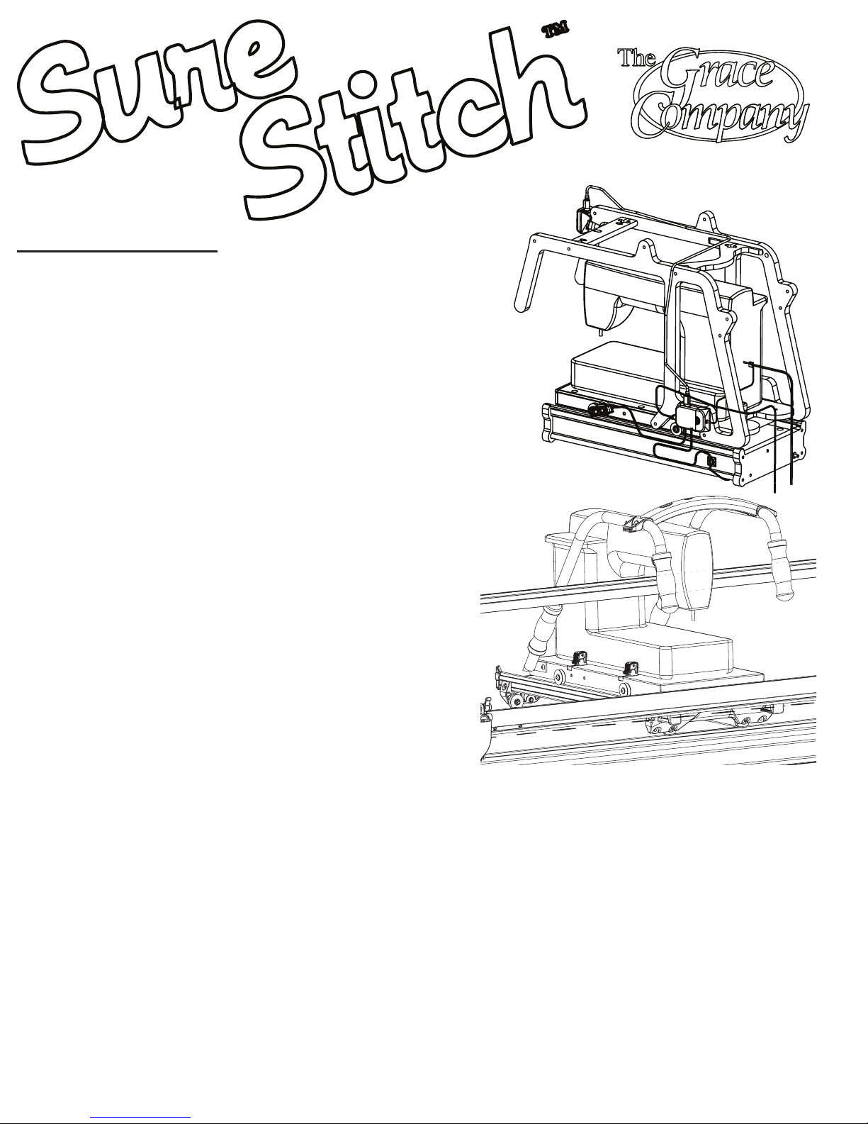
Table of Contents
Wooden Quilting Frames
Display Console Attachment. . . . . . . . .
Top Plate Encoder Attachment . . . . . . .
Bottom Plate Encoder Attachment . . . .
Encoder Wheel Attachment . . . . . . . . .
Controller Attachment . . . . . . . . . . . . .
Wire Attachment. . . . . . . . . . . . . . . . .
Troubleshooting . . . . . . . . . . . . . . . . .
Operating the SureStitch . . . . . . . . . . .
Limited 1 Year Warranty. . . . . . . . . . . .
Jumper Settings . . . . . . . . . . . . . . . . .
Pinnacle Quilting Frames
Display Console Attachment. . . . . . . . .
Top Plate Encoder Attachment . . . . . . .
Bottom Plate Encoder Attachment . . . .
Encoder Wheel Attachment . . . . . . . . .
Controller Attachment . . . . . . . . . . . . .
Wire Attachment. . . . . . . . . . . . . . . . .
Troubleshooting . . . . . . . . . . . . . . . . .
Operating the SureStitch . . . . . . . . . . .
Limited 1 Year Warranty. . . . . . . . . . . .
Jumper Settings . . . . . . . . . . . . . . . . .
User Manual
Pg. 3
Pg. 3
Pg. 4
Pg. 4
Pg. 5
Pg. 5
Pg. 6
Pg. 7
Pg. 7
Pg. 8
Pg. 10
Pg. 10
Pg. 11
Pg. 11
Pg. 12
Pg. 12
Pg. 13
Pg. 14
Pg. 14
Pg. 15
Accessory for other quilting frames
Uiversal Adaptor . . . . . . . . . . . . . . . . .
Pg. 16 - 19
Pg. 1
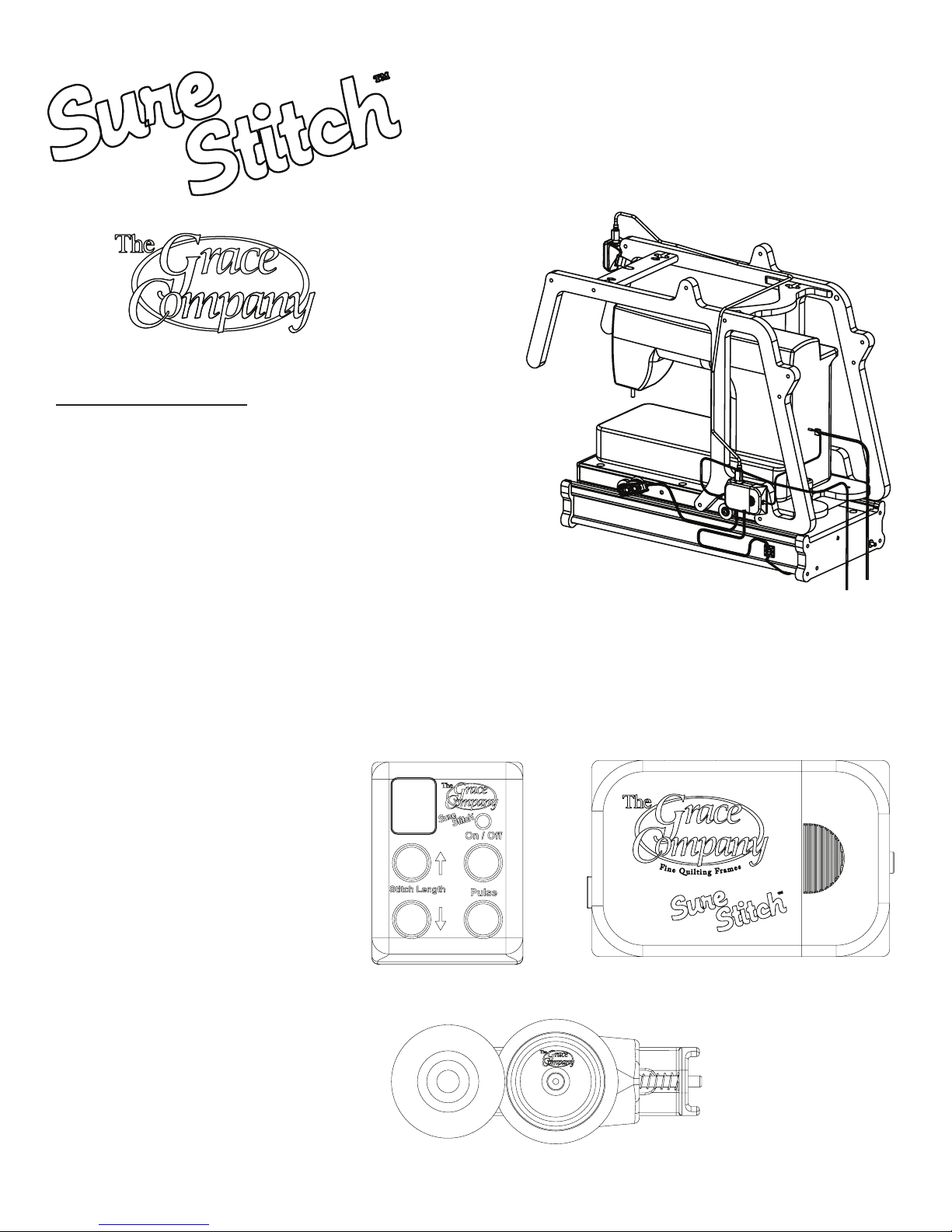
Table of Contents
User Manual for installation
on Wooden Quilting Frames
Display Console Attachment. . . . . . . . .
Top Plate Encoder Attachment . . . . . . .
Bottom Plate Encoder Attachment . . . .
Encoder Wheel Attachment . . . . . . . . .
Controller Attachment . . . . . . . . . . . . .
Wire Attachment. . . . . . . . . . . . . . . . .
Troubleshooting . . . . . . . . . . . . . . . . .
Operating the SureStitch . . . . . . . . . . .
Limited 1 Year Warranty. . . . . . . . . . . .
Jumper Settings . . . . . . . . . . . . . . . . .
Parts Included:
1: Display Console
1: Control Box
2: Encoder (Wires attached)
(Not Shown)
1: 5v Power Supply
1: Display Cable
1: Sewing Machine Control Cable
6: Velcro - Cable Ties
2: Self Adhesive - Tie Mount
2: Zip Tie
Pg. 3
Pg. 3
Pg. 4
Pg. 4
Pg. 5
Pg. 5
Pg. 6
Pg. 7
Pg. 7
Pg. 8
Display Console
Control Box
Encoder
Pg. 2
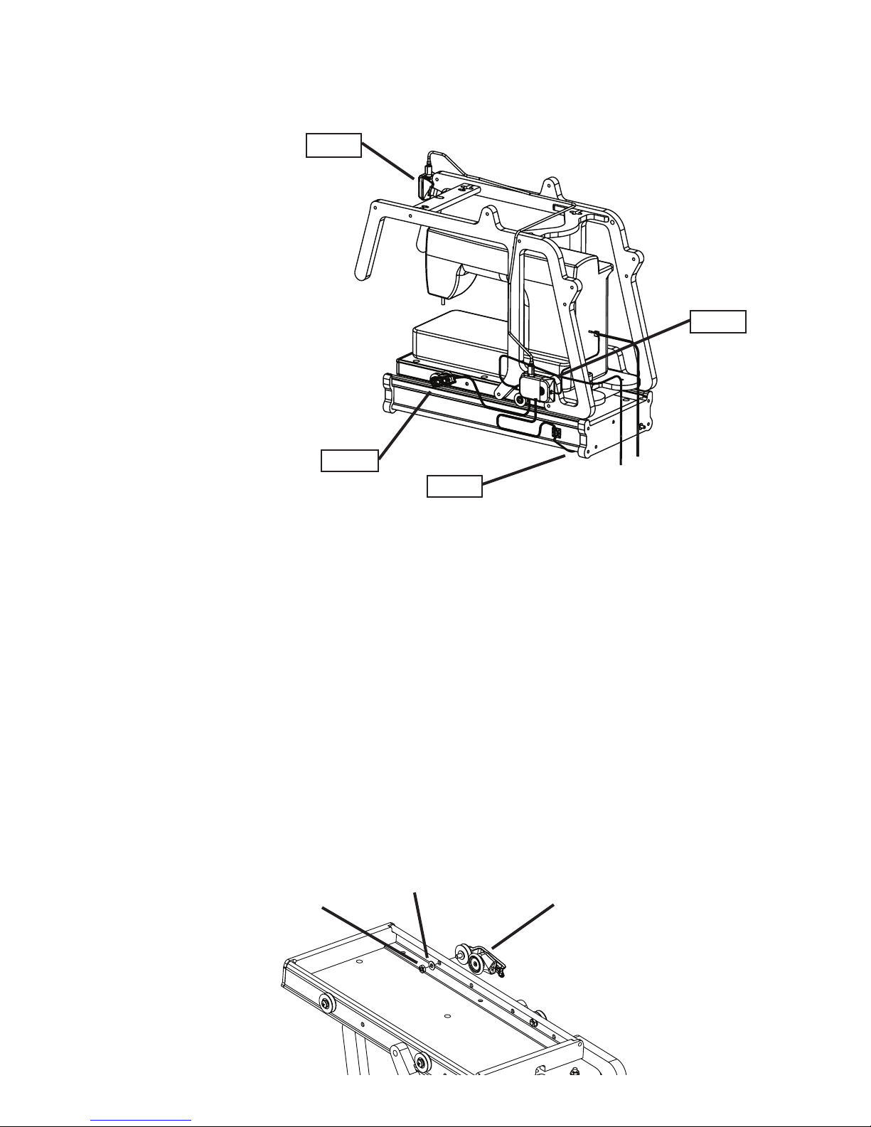
SureStitch - Assembly
Display Console Attachment
Step 1: Secure the Display Console to your quilting frame with the included velcro strap.
Place the Display Console so that it’s controls will be easily accessible while you are quilting.
(NOTE: Wait to attach all wires until Step 5.)
Step 1: Display Console
Step 2: Top Plate Encoder
Step 3: Bottom Plate Encoder
Step 4: Controller
Step 1
Step 4
Fig. 1
Top Plate Encoder Attachment
Step 2-1: If your sewing machine is in place on the carriage, remove it before continuing.
You will also need to turn the top plate up-side down, to be able to access the supporting
hardware.
2-2: Remove one of the front wheels from the top plate before attaching the encoder.
(Attach this encoder to the same side of the carriage that you will attach the Controller, in Step
4, to keep wires more organized.)
2-3: Remove the 6mm Hex nut, and the rst washer from the encoder with the shorter bolt
through the wheel (25mm).
2-4: Place the exposed end of the bolt on the Encoder through the hole that the wheel that
you just removed, was in.
2-5: Apply the Washer, and 6mm nut back onto the bolt. Tighten the nut securely. When
you tighten the nut, make sure that the encoders moving parts don’t contact any part of the
carriage. When the top plate is sitting upright, the encoder should be angled up slightly, so
that the encoder’s wheel doesn’t touch the track on the Bottom Plate. (See Fig. 1).
Step 2
Step 3
6mm Hex nut
Washer
Encoder with 25mm bolt
Fig. 2
Pg. 3
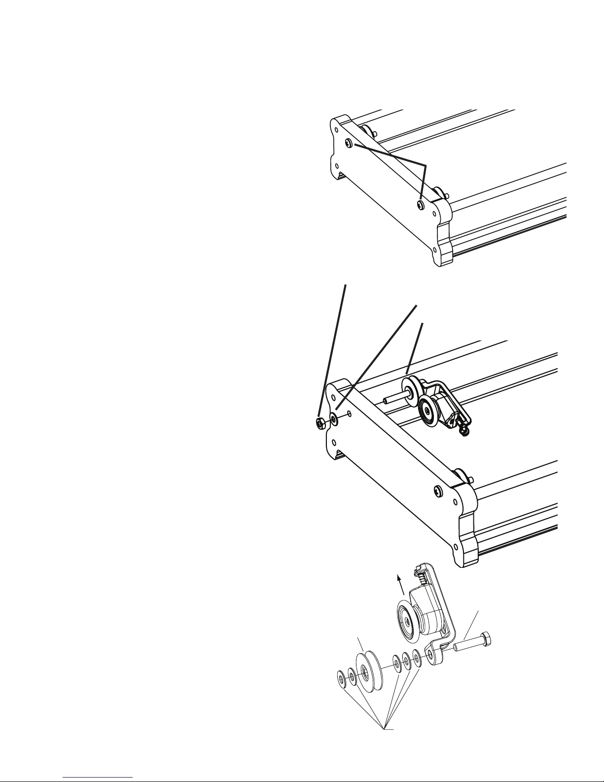
Bottom Plate Encoder Attachment
NOTE: THE WHEELS ON ONE END OF THE BOTTOM PLATE ARE
ATTACHED AS SHOWN IN Fig. 3-1. REMOVE ONE OF THESE
WHEELS IN STEP 3-1. The wheels attached to the other end of the Bottom Plate can’t be
used to attach an encoder.
Step 3-1: Remove one of the wheels from
the bottom plate before attaching the encoder.
(Attach this encoder to the opposite side of the
carriage as you attached the encoder on the
top plate.)
3-2: Remove the 6mm Hex nut, and the rst
washer from the remaining encoder. This
encoder should have the longer bolt through
the wheel (40mm).
3-3: Place the exposed end of the bolt on the
Encoder through the hole that the wheel that
you just removed, was in. Fig. 3-2
3-4: Apply the Washer, and 6mm nut back
onto the bolt. Tighten the nut securely.
When you tighten the nut make sure that the
encoders moving parts don’t contact any part of
the carriage. When the bottom plate is sitting
upright, the encoder should be angled up
slightly, so that the encoder wheel won’t touch
the Table Track..
Phillips Head Screw
Fig. 3-1
6mm Hex Nut
Washer
Encoder with 40mm bolt
Fig. 3-2
Encoder Wheel Attachment
This section is provided so you can
properly attach a wheel to your
encoder, if you ever need to put
a wheel onto the encoder. The
process is identical for any bolt
used.
Slide Encoder up, to allow
Encoder Wheel to t into
Carriage Wheel
6mm Hex Bolt
CarriageWheel
Washer
Pg. 4
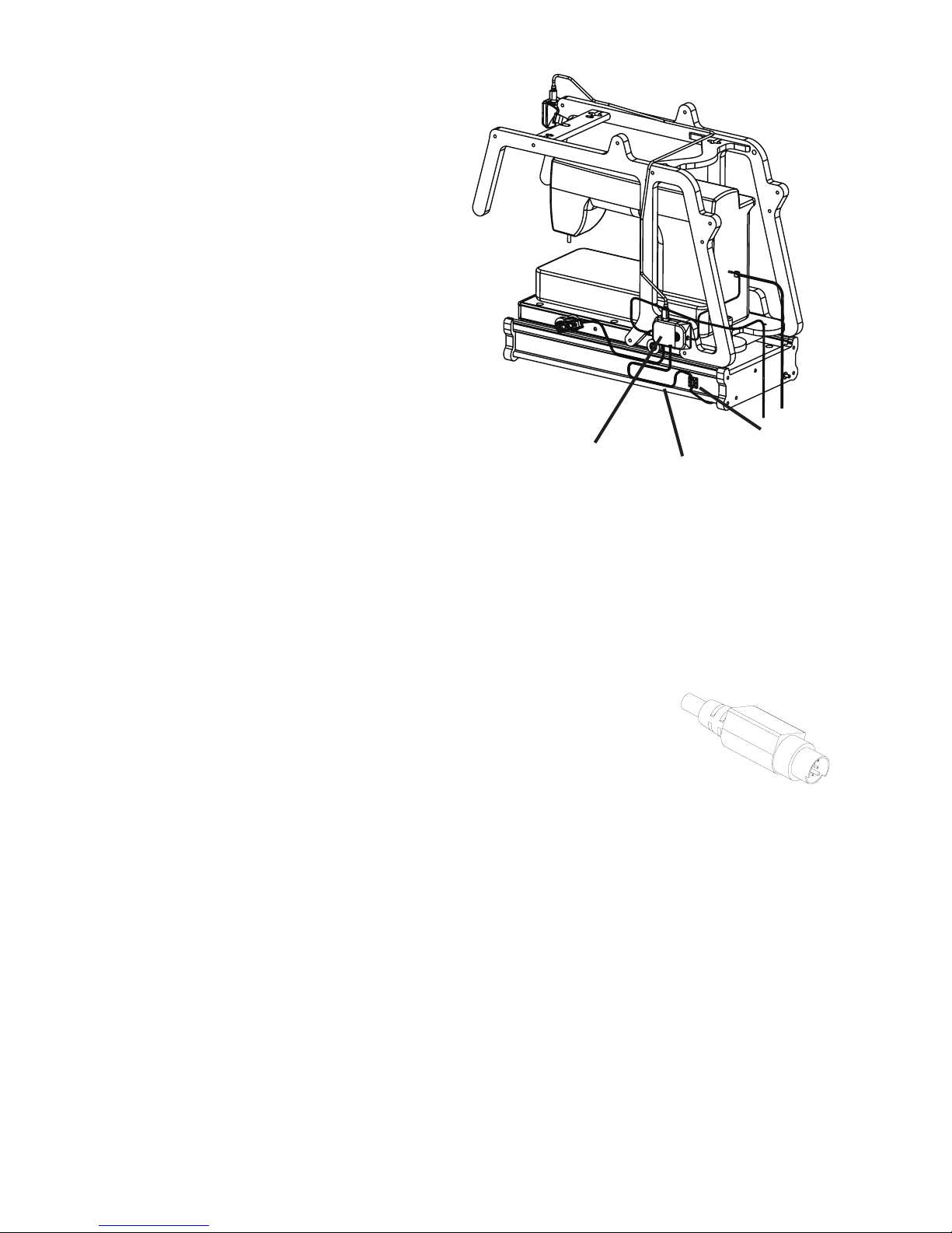
Controller Attachment
Step 4-1: Place your bottom, and top plates back onto your quilting machine. Also, Place your
sewing machine back onto the carriage.
NOTE: One end of all SureStitch wires are
attached to the Controller. Determine a place
to mount the Controller where it, or the wires
attached to it do not obstruct other features on
your quilting frame, or sewing machine. (Ideal
locations to mount the Controller are on the
lower portion of one of the carriage handles (see
Fig. 4), or directly to the back of your sewing
machine, other locations may also work better for
you.)
4-2: Remove the backing from the adhesive on
the back of the Controller.
Fig. 4
4-3: Adhere the Controller to the location that
you have determined to be the most convenient.
Controller
Bottom Plate
Tie Mount
Encoder Wire
Wire Attachment
NOTE:
• When wiring the SureStitch make sure that your sewing machine is turned off, and unplugged from
power, (this will ensure that when your sewing machine is turned on and accept the SureStitch as it’s
speed control).
• Leave a little slack in the wires near the wire connectors, to prevent the connector from being
pulled out, or damaged.
• Secure wires to carriage with the included velcro straps, tie mounts,
and zip ties. Keep wires taut between the velcro straps, and keep the
wires neat.
• When there is more wire than you need, coil up the extra wire,
and secure it to the carriage out of the way.
Display Wire Connector
Fig. 5-1
Step 5-1: Attach the Display wire (See Fig. 5-1, and Fig 5-2) to the Display Console, and to the
Controller. Be sure to line up the pins in the connectors to prevent bending them. Secure the wire to
the carriage to keep the wire neat.
5-2: Attach the wires from each of the encoders to the controller. It doesn’t matter which wire goes
into either of the (Telephone Type) connectors. Secure the encoder wires to the carriage using Tie
Mounts, and Zip Ties to keep the wires neat.
NOTE: When securing the wires for the bottom plate encoder, be sure to include enough slack to
allow your top plate to travel it’s entire available distance. This will prevent damage to the encoder
wire. Also, use a tie mount to secure the encoder wire to the bottom plate to prevent the wire from
rubbing on the quilting machine table when the carriage is being moved.
Pg. 5
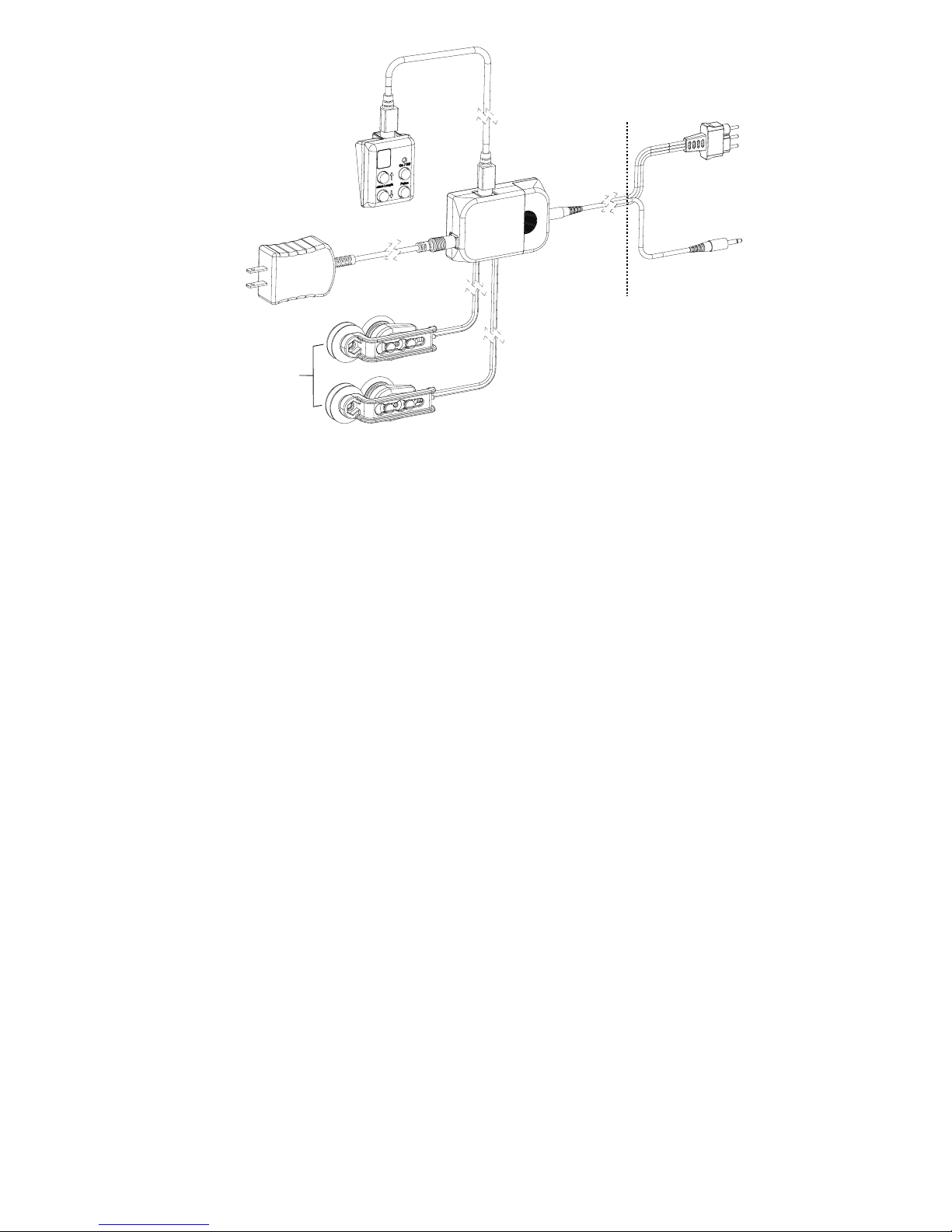
Wiring Diagram
To Sewing Machine
Display
Power Supply
(Appearance may vary)
Control Box
Note: You will recieve one (1) of the cords
shown above depending on the model of
sewing machine that your have.
Encoders
3 Prong Plug
Viking, PFAFF,
Janomi 1600
1 Prong Plug
All other compatible
Sewing Machines
Fig. 5-2
5-3: Connect the sewing machine control wire to the Controller, and also to the location on
your sewing machine where the foot pedal attaches.
5-4: Plug your sewing machine into an available power outlet, but do not turn on your sewing
machine. Connect the 5 volt power supply to the Controller. Plug the 5 volt power supply
into an available power outlet. (The power supply needs to be connected to a cord that is
long enough to allow the carriage to travel the entire length of the quilting frame.) It is OK to
leave the SureStitch connected to a power source, when not in use. If you do disconnect the
SureStitch from power, be sure to re-attach the unit to power before turning on your sewing
machine.
5-5: Verify that all wires are correctly attached. When the SureStitch is rst connected to
power, the LED panel on the display should show a number 5.
Troubleshooting
If you are experiencing problems.
T-1: Turn the sewing machine off.
T-2: Pull power cord out of SureStitch control box.
T-3: Plug power cord back into SureStitch.
T-4: Turn sewing machine on.
Because of your sewing machine’s built-in safety features, sometimes the machine will not
respond to your movement of the carriage and needs to be reset.
If your machine is running at an unusually slow speed, reset your machine and SureStitch
using the following steps.
T2-1: Turn sewing machine off.
T2-2: Unplug sewing machine from the wall, wait 5 seconds, and plug back in.
T2-3: Pull power cord out of SureStitch control box.
T2-4: Plug power cord back into SureStitch.
T2-5: Turn sewing machine back on.
Pg. 6
 Loading...