

Grace Company Q'nique 21 Service Manual
Service Manual
21

|Table of Contents Q’nique 21: Service Manual
Bobbin Winder ............................................................................................................................ 1
Display Board Box ....................................................................................................................... 2
Needle Bar Height ....................................................................................................................... 3
Hopping Foot Height .................................................................................................................... 4
Hook Holder ............................................................................................................................... 5
Needle Plate ............................................................................................................................... 6
Handle Bars ................................................................................................................................ 6
Timing ........................................................................................................................................ 7
Thread Tensioner ........................................................................................................................ 9
Adjusting Thread Tensioner .........................................................................................................10
Extrusions Cover ........................................................................................................................11
Front Cover ................................................................................................................................12
Needle Rod Holders ....................................................................................................................13
Upper Shaft ...............................................................................................................................14
Pulley and Optical Encoding Wheel ..............................................................................................15
LED Assembly ............................................................................................................................15
Lower Shaft ...............................................................................................................................16
Bushing Block ............................................................................................................................17
Bushing Block ............................................................................................................................18
Main Board ................................................................................................................................19
Power Supply .............................................................................................................................20
Motor Driver Board ....................................................................................................................21
Grounding Wire ..........................................................................................................................21
Idler Pulley Tension ....................................................................................................................22
MCU Board Update .....................................................................................................................23
Motor Driver Board .....................................................................................................................26
Motor Driver Board Plugs ............................................................................................................26
Self Calibration Instructions ........................................................................................................27
Window Offset Adjustment Instructions .......................................................................................28
Encoder Test ..............................................................................................................................29
Button Test ................................................................................................................................29
Sensor Test ................................................................................................................................30
i
Tools Needed:
9mm Crescent Wrench
1.5mm Allen Wrench
|Bobbin Winder Q’nique 21: Service Manual
Set
Screw
Tension
Disc Post
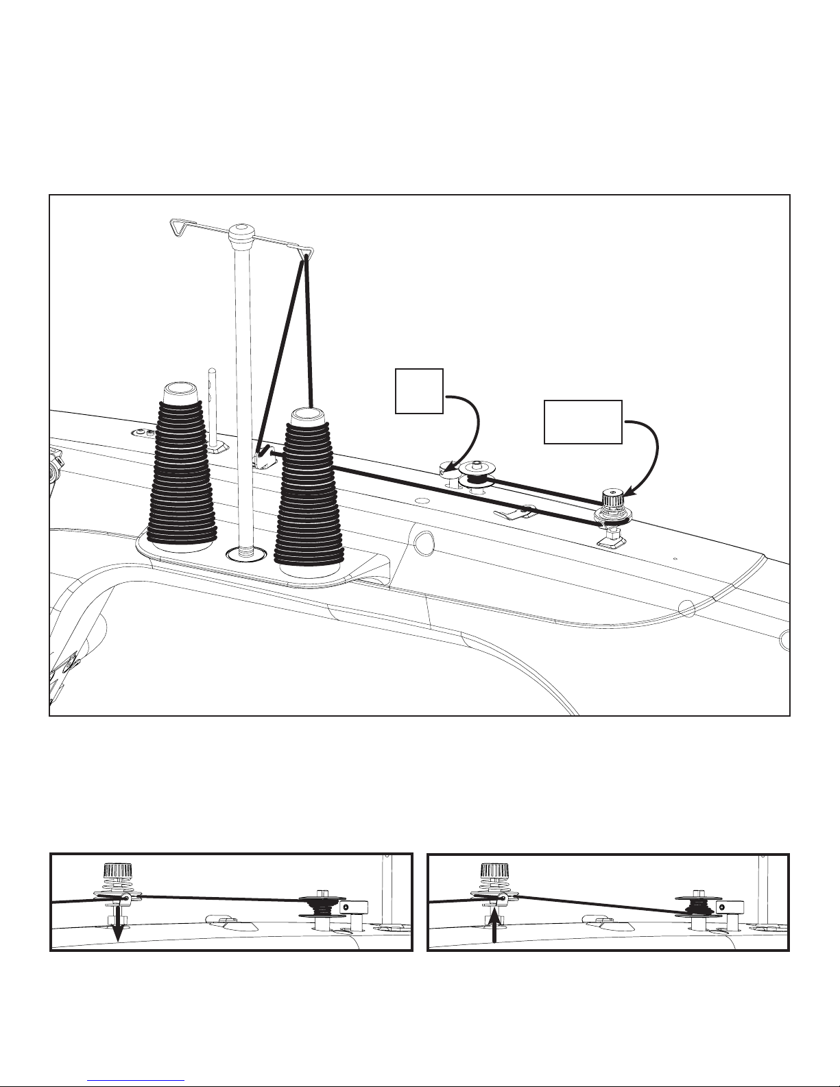
1. Adjust the Bobbin Winder Cam to be centered to the Bobbin without touching it by loosening the
Set Screw with the 1.5 mm Allen Wrench, adjusting the Cam, and retightening the Set Screw. If
thread winds mostly on the top of the bobbin, the Tension Discs Post will need to be lowered by
twisting the Tension Disc Post clockwise and retightening the hex nut.
2. If thread winds mostly on the top of the
bobbin, the Tension Disc Post will need to be
heightened by twisting the Tension Disc Post
clockwise and retightening the hex nut.
3. If thread winds mostly on the bottom of the
bobbin, the Tension Disc Post will need to be
heightened by twisting it counter clockwise and
retightening the hex nut.
1
2
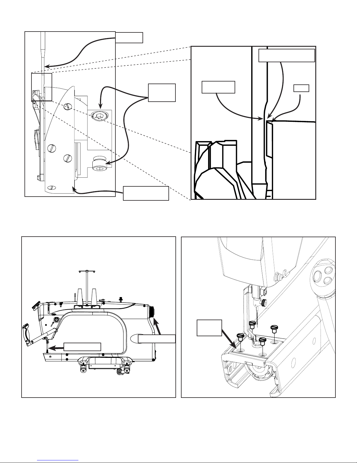
Tools Needed:
3mm Allen Wrench
Screen
Assembly
Tab
|Display Board Box Q’nique 21: Service Manual
Screen
Assembly
M5 x 16mm
Board Box
SBHCS
Display
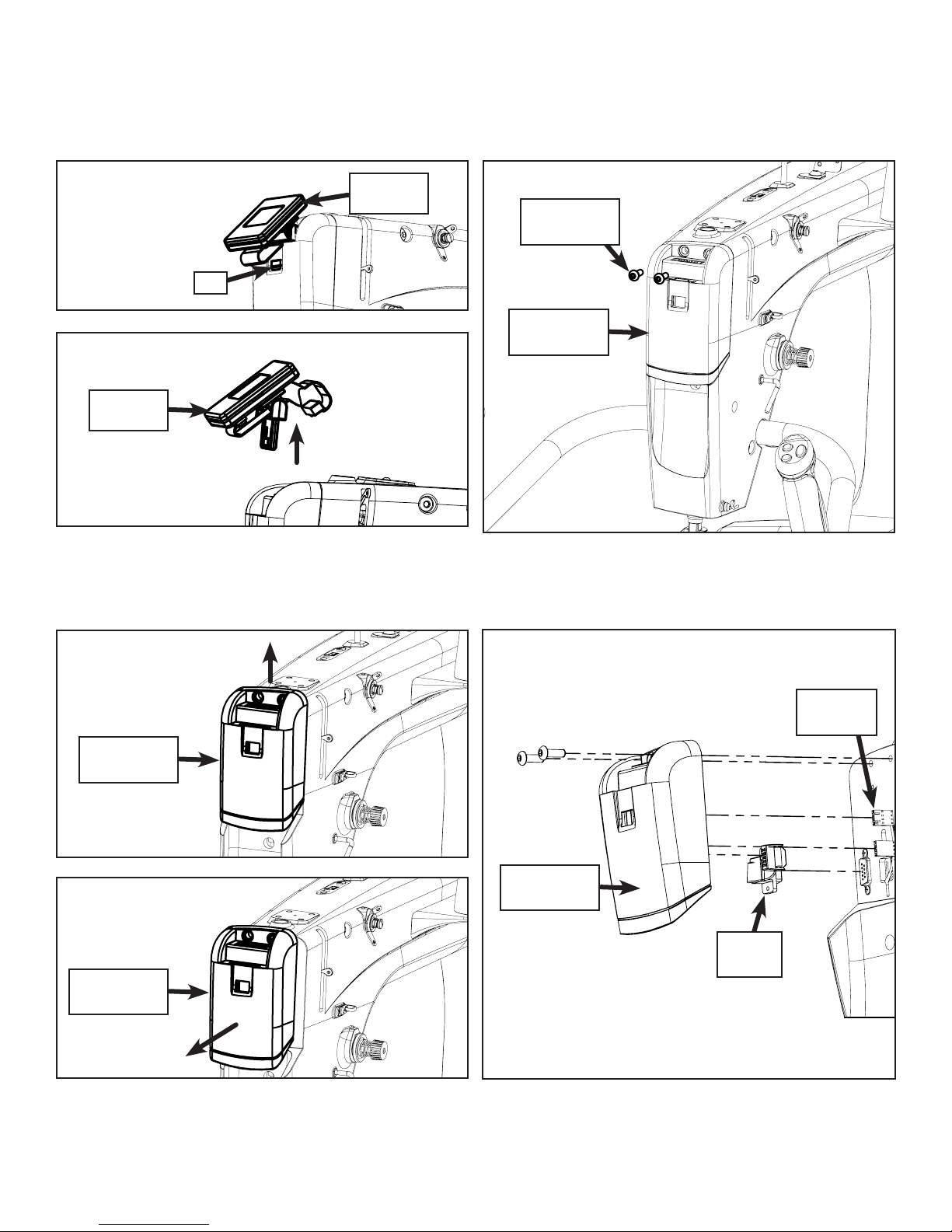
1. Press the Tab inward and pull the Screen
Assembly up and unplug the LCD Cable.
Display
Board Box
Display
Board Box
2. Remove the (2) M5 x 16mm SBHCS holding the
Display Board Box.
Handle
Cables (2)
Display
Board Box
Display
Cable
3. Pull the Display Board Box up and out.
4. Unplug the Handle Cables and Display Cable
and remove.
2
Tools Needed:
Flat Head Screwdriver
Needle Bar Height Spacer
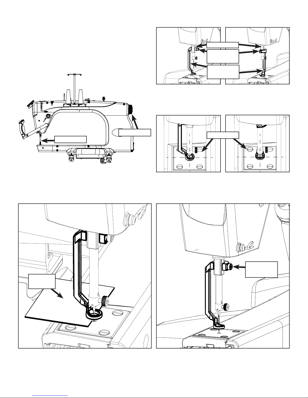
|Needle Bar Height Q’nique 21: Service Manual
Adjust Needle
Bar height with a
Flat Head Screw
Driver here.
*Note: Display Board Box may
have to be removed to access.
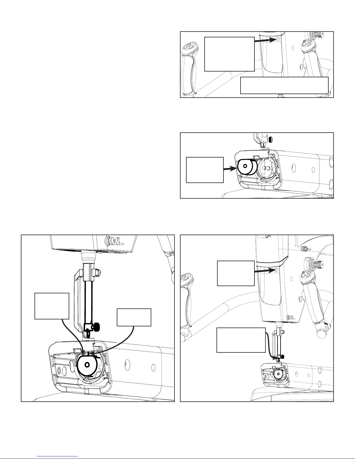
1. Rotate the hand wheel in the back of the
machine until the Needle Bar is in the lowest
position. Loosen screw inside sewing machine
head using a flat head screw driver.
Needle
Bar Height
Spacer
Height
Spacer
Flat Spot
2. Place the Needle Bar Height Spacer into the
Bobbin Case area.
Tighten
Screw inside
this hole
Tip of
Needle
Thread Guide
faces front
of machine
3. Using a Needle Bar Height Spacer bring the
Needle Bar down till the tip of the Needle is
resting on the flat surface of the Needle Bar
Height Spacer.
4. Tighten the screw inside the head of your
machine with a flat head screw driver, make
sure the Needle Bar is facing forward so the
thread guide is in the front of your machine.
3
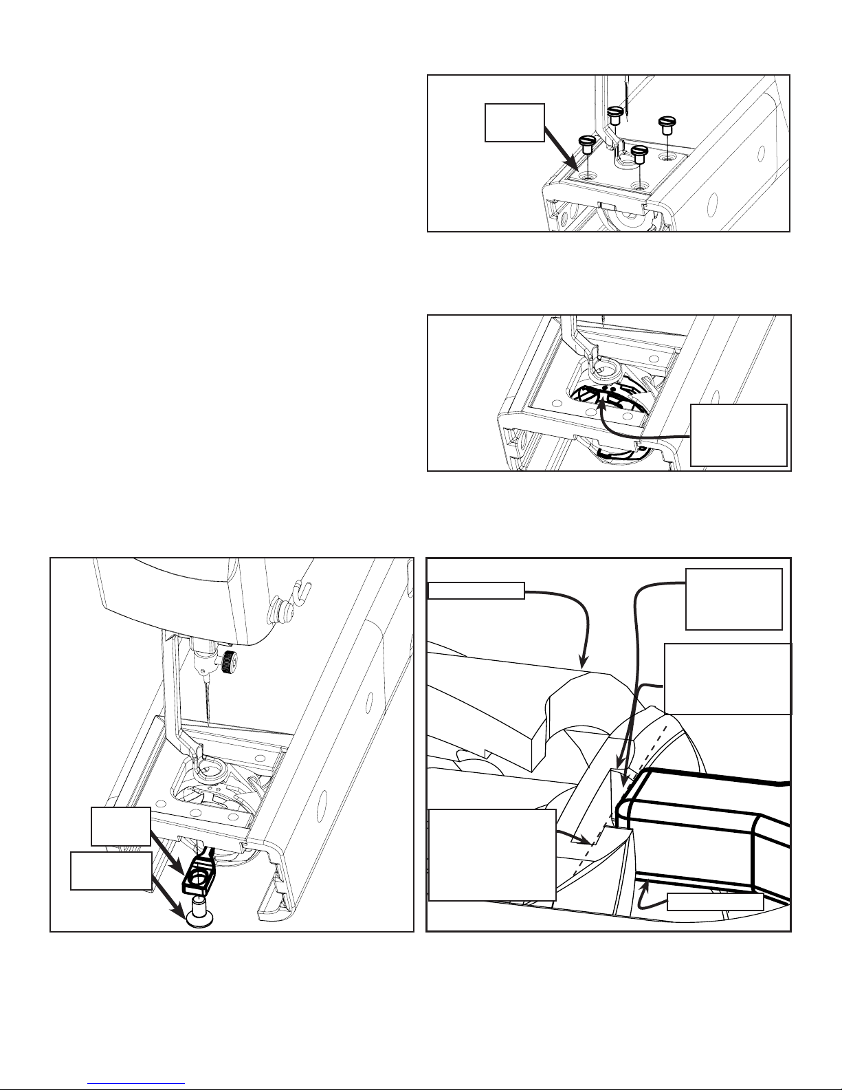
Tools Needed:
|Hopping Foot Height Q’nique 21: Service Manual
3mm Allen Wrench
Hand Wheel
Needle Bar
2. Using the Hand Wheel in the back of your
machine, rotate your machine until the Needle
Bar is in the lowest position.
Press Bar
M3 Socket
Head Screw
Hopping
Foot
1. Attach your Hopping Foot to the press bar
using a M3 Socket Head Screw (don’t tighten
during this step) in either of the configurations
shown.
Needle Plate
3. Using the hole in the Needle Plate, align the
Hopping Foot so that it is centered.
.5mm Gap
Gauge
4. Place 2-6 sheets of paper under the foot and
lower the Hopping Foot to the top of the
surface depending on the thickness of your
project.
M3 Socket
Head Screw
5. Tighten the M3 socket head screw using the 3
mm Allen wrench.
*Note: Do not over tighten, this will
cause sewing machine to bind.
4
Tools Needed:
|Hook Holder Q’nique 21: Service Manual
3mm Allen Wrench
Flat Head Screwdriver
Needle
Plate
1. Remove the Needle Plate.
Hook Assembly
Positioning
Guide
2. Rotate your Hook Assembly so that the
positioning guide is at the highest point during
rotation.
Hook
Holder
M5 x 10mm
FHCS
3. Attach your Hook Holder to your sewing
machine with a M5 X 10mm FHCS (don’t
tighten the screw during this step) with the
Hook Holder’s finger in the middle of the Hook
Assembly’s positioning guide.
Hook Assembly
It’s hard to measure
so just make it so
tip of Hook Holder is
ush with Positioning
Guide Finger
Hook Assembly
Positioning
Guide
0.75mm Gap
between Hook
Holder and Hook
Assembly
Hook Holder
4. Slide your Hook Holder away from the Hook
Assembly so there is about a 0.75mm gap
between the Hook Holder and the Hook
Assembly, and tighten the M5 X 10mm FHCS.
5
Tools Needed:
Flat Head Screwdriver
Needle Plate
Screws (4)
|Needle Plate Q’nique 21: Service Manual
Needle
Plate
Needle in
Lowest
Position
1. Attach your Needle Plate using (4) Needle Plate
Screws, don’t tighten the screws during this
step.
2. Rotate Hand Wheel until the Needle is in the
lowest position. Move the Needle Plate until it
is centered around the Needle and tighten all
(4) Needle Plate Screws.
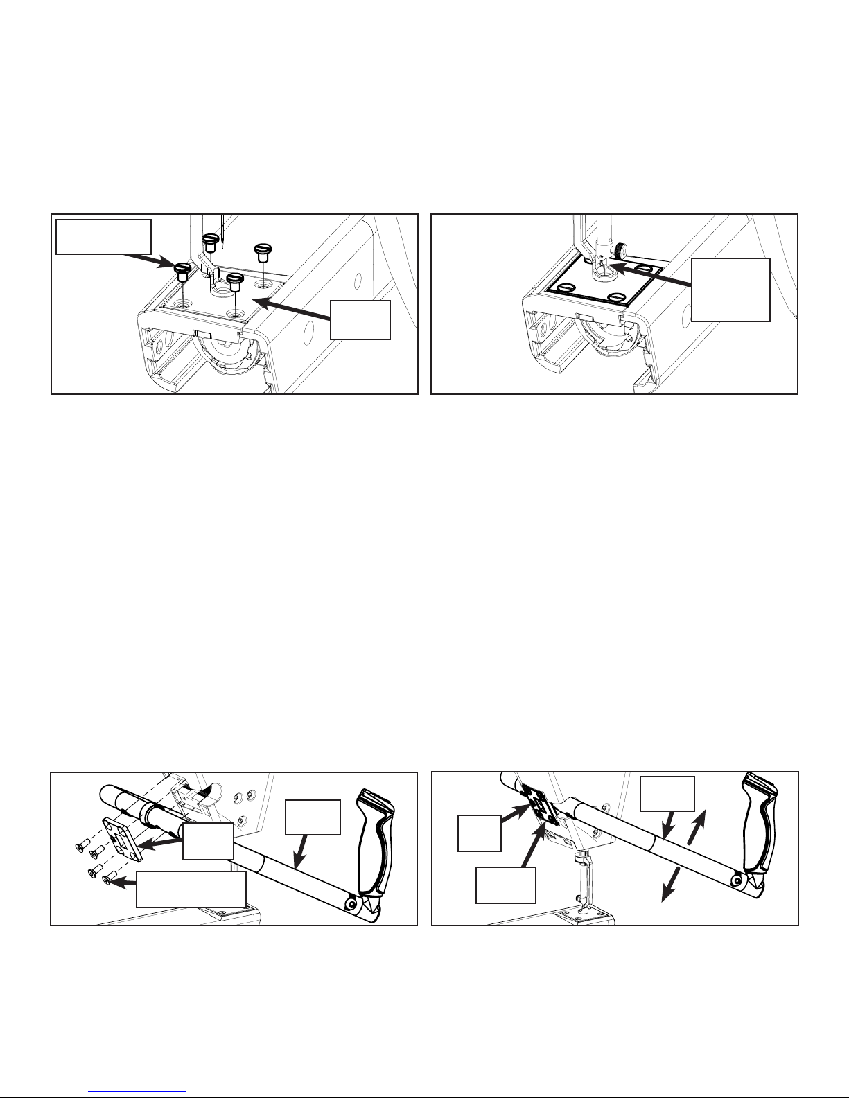
Handle Bars
Tools Needed:
5mm Allen Wrench
4mm Allen Wrench
To Remove: To Adjust:
Handle
Handle
Plate
Bars
Set
Screw
Handle
Bars
M6 x 16mm
Socket FCHS (4)
1. Using the 4mm Allen Wrench, remove the (4)
Screws from the Handle Plate. Remove the
Handle Plate and the Handle Bars
Handle
Plate
1. Adjust the Handles up and down by tightening
and loosening the Set Screw on the back of the
Handle Plate using the 5mm Allen Wrench.
6
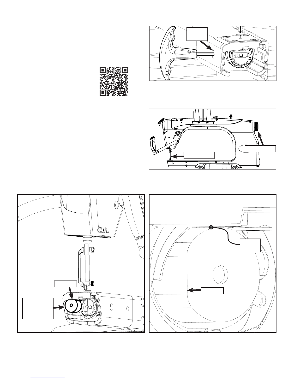
|Timing Q’nique 21: Service Manual
Tools Needed:
2mm Allen Wrench
Timing Spacer
Flat Head Screwdriver
A timing tutorial is available on
our website at:
http://www.qniquequilter.com/
videos/tutorials/
Timing
Hole
1. Loosen all 3 Hook Assembly Set Screws with a
2mm Allen Wrench by inserting the wrench into
the Timing Hole when each Set Screw aligns
with the hole.
Hand Wheel
Needle Bar
Needle
Bar Height
Spacer
2. Rotate the hand wheel clockwise from the front
of the machine so needle is rising out of the
Hook Assembly.
Tip Of
Needle
Flat Side
Flat Side
3. Place the Needle Bar Height Spacer into the
Bobbin Case area and twist so that flat side is
vertical.
4. Bring the Needle so it rests on the top of the
Needle Bar Height Spacer, so the groove in the
needle aligns in the middle of the hook on the
Hook Assembly.
7
Needle
0.02-0.75mm Gap
Set
Screws
Hook Assembly
Scarf
Hook
5. The Needle should be as close as possible to the Hook Assembly without touching, roughly between
0.02mm and 0.075mm. Tighten the Set Screw which is currently aligned with the Timing Hole on
the left side of the machine.
Needle Bar
6. Rotate the hand wheel a full rotation. If the
needle hits the Hook Assembly anywhere,
the needle will bend or there will be a clicking
noise. Adjust the needle height closer or
farther off from the hook.
Needle
Plate
Hand Wheel
7. Tighten the two remaining set screws and
reattach the Needle Plate.
8
 Loading...