

Page 1
INSTRUCTIONS-PARTS LIST
308–560
This manual contains important
warnings and information.
READ AND KEEP FOR REFERENCE.
INSTRUCTIONS
220/240 VAC, 8 AMP
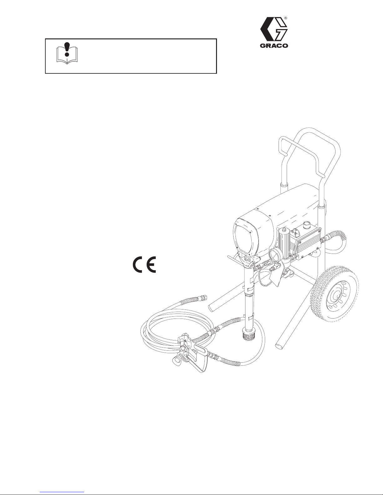
ULTRAr
PLUS+
1000
AIRLESS PAINT SPRAYER
210 bar (3000 psi) Maximum Working Pressure
Model 231–350 Series A
Complete sprayer on Upright cart with hose,
gun, RAC IVt DripLesst Tip Guard
and SwitchTipt
Rev. D
Supersedes Rev. B
and unreleased Rev. C
U.S. PATENT NO. 4,323,741; 4,397,610
PATENTED 1983, CANADA
AND OTHER PATENTS PENDING
04794
GRACO INC. P.O. BOX 1441 MINNEAPOLIS, MN 55440–1441
ECOPYRIGHT 1995, GRACO INC.
Graco Inc. is registered to I.S. EN ISO 9001
Page 2
Table of Contents
Warnings 2. . . . . . . . . . . . . . . . . . . . . . . . . . . . . . . . . . . . . .
Setup 6. . . . . . . . . . . . . . . . . . . . . . . . . . . . . . . . . . . . . . . . .
Startup 8. . . . . . . . . . . . . . . . . . . . . . . . . . . . . . . . . . . . . . . .
Shutdown and Care 10. . . . . . . . . . . . . . . . . . . . . . . . . . .
Flushing 11. . . . . . . . . . . . . . . . . . . . . . . . . . . . . . . . . . . . . .
Troubleshooting 12. . . . . . . . . . . . . . . . . . . . . . . . . . . . . . .
Spin Test 17. . . . . . . . . . . . . . . . . . . . . . . . . . . . . . . . . . . . .
General Repair Information 18. . . . . . . . . . . . . . . . . . . . .
Motor Brush Replacement 19. . . . . . . . . . . . . . . . . . . . .
Power Supply Cord Replacement 20. . . . . . . . . . . . . . .
On/Off Switch Replacement 21. . . . . . . . . . . . . . . . . . . .
Pressure Control Replacement 22. . . . . . . . . . . . . . . . .
Filter Board Replacement 23. . . . . . . . . . . . . . . . . . . . . .
Bearing Housing & Connecting Rod Replacement 24.
Symbols
Warning Symbol
Drive Housing Replacement 25. . . . . . . . . . . . . . . . . . . .
Motor Replacement 27. . . . . . . . . . . . . . . . . . . . . . . . . . . .
Displacement Pump Repair 29. . . . . . . . . . . . . . . . . . . . .
Parts Drawing – Sprayer 34. . . . . . . . . . . . . . . . . . . . . . .
Parts List – Sprayer 35. . . . . . . . . . . . . . . . . . . . . . . . . . .
Parts Drawing and List – Displacement Pump 36. . . . .
Parts Drawing – Pressure Control 37. . . . . . . . . . . . . . .
Parts List – Pressure Control 37. . . . . . . . . . . . . . . . . . . .
Wiring Diagram 38. . . . . . . . . . . . . . . . . . . . . . . . . . . . . . .
Accessories 39. . . . . . . . . . . . . . . . . . . . . . . . . . . . . . . . . .
Technical Data 39. . . . . . . . . . . . . . . . . . . . . . . . . . . . . . . .
Dimensions 40. . . . . . . . . . . . . . . . . . . . . . . . . . . . . . . . . . .
Graco Phone Numbers 40. . . . . . . . . . . . . . . . . . . . . . . . .
The Graco Warranty And Disclaimers 40. . . . . . . . . . . .
Caution Symbol
WARNING
This symbol alerts you to the possibility of serious
injury or death if you do not follow the instructions.
WARNING
FIRE AND EXPLOSION HAZARD
Improper grounding, poor ventilation, open flames or sparks can cause a hazardous condition and
result in a fire or explosion and serious injury.
If there is any static sparking or you feel an electric shock while using this equipment, stop
spraying immediately. Do not use the equipment until you identify and correct the problem.
Provide fresh air ventilation to avoid the buildup of flammable fumes from solvents or the fluid
being sprayed.
Keep the spray area free of debris, including solvent, rags, and gasoline.
Electrically disconnect all equipment in the spray area.
CAUTION
This symbol alerts you to the possibility of damage to
or destruction of equipment if you do not follow the
instructions.
Extinguish all open flames or pilot lights in the spray area.
Do not smoke in the spray area.
Do not turn on or off any light switch in the spray area while operating or if fumes are present.
Do not operate a gasoline engine in the spray area.
2 308-560
Page 3
INSTRUCTIONS
WARNINGWARNING
EQUIPMENT MISUSE HAZARD
Equipment misuse can cause the equipment to rupture or malfunction and result in serious injury.
This equipment is for professional use only.
Read all instruction manuals, tags, and labels before operating the equipment.
Use the equipment only for its intended purpose. If you are not sure, call Graco Technical Assis-
tance at 1–800–543–0339.
Do not alter or modify this equipment.
Check equipment daily. Repair or replace worn or damaged parts immediately.
Do not exceed the maximum working pressure of the lowest rated system component. Refer to
the Technical Data on page 39 for the maximum working pressure of this equipment.
Use fluids and solvents which are compatible with the equipment wetted parts. Refer to the
Technical Data section of all equipment manuals. Read the fluid and solvent manufacturer’s
warnings.
Do not use 1,1,1–trichloroethane, methylene chloride, other halogenated hydrocarbon solvents or
fluids containing such solvents in pressurized aluminum equipment. Such use could result in a
chemical reaction, with the possibility of explosion.
Do not use hoses to pull equipment.
Route hoses away from traffic areas, sharp edges, moving parts, and hot surfaces. Do not ex-
pose Graco hoses to temperatures above 82C (180F) or below –40C (–40F).
Do not lift pressurized equipment.
Comply with all applicable local, state, and national fire, electrical, and safety regulations.
Wear hearing protection when operating this equipment.
TOXIC FLUID HAZARD
Hazardous fluid or toxic fumes can cause serious injury or death if splashed in the eyes or on the
skin, inhaled, or swallowed.
Know the specific hazards of the fluid you are using.
Store hazardous fluid in an approved container. Dispose of hazardous fluid according to all local,
state and national guidelines.
Always wear protective eyewear, gloves, clothing and respirator as recommended by the fluid
and solvent manufacturer.
MOVING PARTS HAZARD
Moving parts, such as the air motor piston, can pinch or amputate your fingers.
Keep clear of all moving parts when starting or operating the pump.
Before servicing the equipment, follow the Pressure Relief Procedure on page 12 to prevent the
equipment from starting unexpectedly.
Page 4
WARNINGWARNING
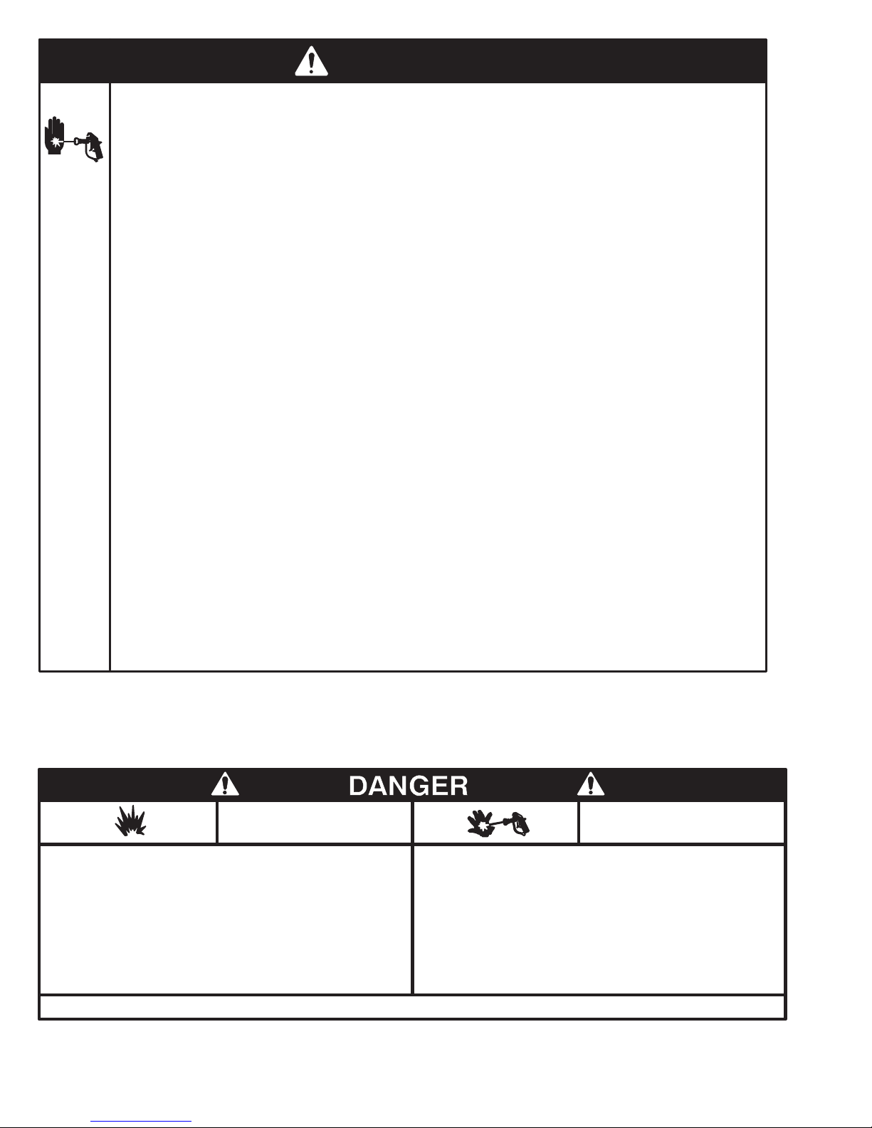
INJECTION HAZARD
Spray from the gun, leaks or ruptured components can inject fluid into your body and cause extremely serious injury, including the need for amputation. Fluid splashed in the eyes or on the skin
can also cause serious injury.
Fluid injected into the skin is a serious injury. The injury may look like just a cut, but it is a serious
injury. Get immediate medical attention.
Do not point the gun at anyone or at any part of the body.
Do not put your hand or fingers over the spray tip.
Do not stop or deflect leaks with your hand, body, glove or rag.
Do not “blow back” fluid; this is not an air spray system.
Always have the tip guard and the trigger guard on the gun when spraying.
Check the gun diffuser operation weekly. Refer to the gun manual.
Be sure the gun trigger safety operates before spraying.
Lock the gun trigger safety when you stop spraying.
Follow the Pressure Relief Procedure on page 12 if the spray tip clogs and before cleaning,
checking or servicing the equipment.
Tighten all fluid connections before operating the equipment.
Check the hoses, tubes, and couplings daily. Replace worn or damaged parts immediately. Do
not repair high pressure couplings; you must replace the entire hose.
Fluid hoses must have spring guards on both ends, to help protect them from rupture caused by
kinks or bends near the couplings.
NOTE: This is an example of the DANGER label on your sprayer. This label is available in other languages,
free of charge. See page 39 to order.
FIRE AND
EXPLOSION HAZARD
Spray painting, flushing or cleaning equipment with flammable liquids in
confined areas can result in fire or explosion.
Use outdoors or in extremely well ventilated areas. Ground equipment,
hoses, containers and objects being sprayed.
Avoid all ignition sources such as static electricity from plastic drop
cloths, open flames such as pilot lights, hot objects such as cigarettes,
arcs from connecting or disconnecting power cords or turning light
switches on and off.
Failure to follow this warning can result in death or serious injury.
READ AND UNDERSTAND ALL LABELS AND INSTRUCTION MANUALS BEFORE USE
Liquids can be injected into the body by high pressure airless spray or
leaks – especially hose leaks.
Keep body clear of the nozzle. Never stop leaks with any part of the
body. Drain all pressure before removing parts.Avoid accidental triggering of gun by always setting safety latch when not spraying.
Never spray without a tip guard.
In case of accidental skin injection, seek immediate
“Surgical Treatment”.
Failure to follow this warning can result in amputation or serious
injury.
SKIN INJECTION
HAZARD
4 308-560
Page 5
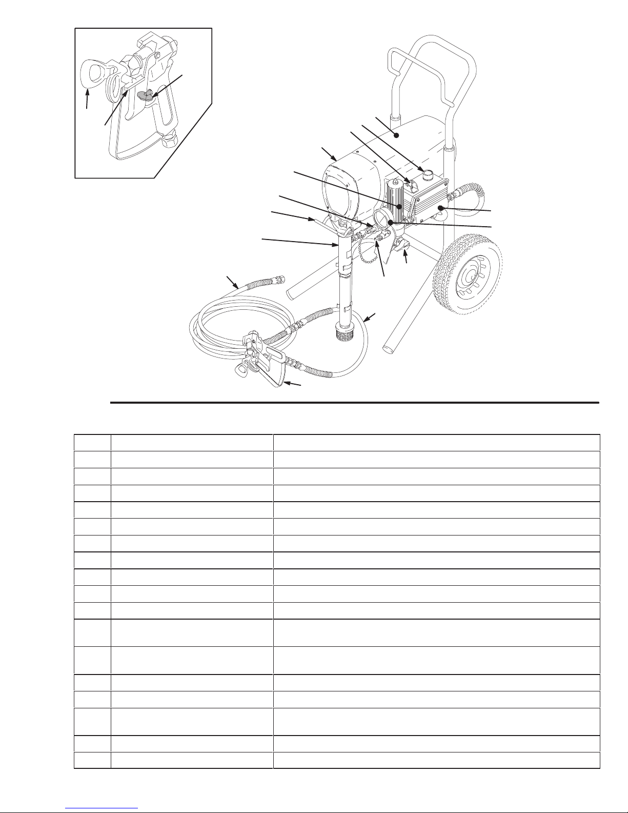
Major Components
T
K
M
0137
Fig. 1
A
B
C
D
E
F
G
S
U
H
J
R
P
N
L
04794
A Motor DC motor, 220/240 Vac, 50 Hz, 8A, 1 phase
B Pressure Adjusting Knob Controls fluid outlet pressure
C ON/OFF Switch Power switch that controls 220/240 Vac main power to sprayer
D Drive Assembly Transfers power from DC motor to the displacement pump
E Fluid Filter Final filter of fluid between source and spray gun
F Secondary Fluid Outlet Second spray gun operation is connected here
G Pail Hanger Container for fluid to be sprayed may be hung here
H Displacement Pump Transfers fluid to be sprayed from source through spray gun
J 50 ft (15 m) Main Hose 1/4 in. ID, grounded, nylon hose with spring guards on both ends
K RAC IV Tip Guard Reverse-A-Clean (RAC) tip guard reduces risk of injection injury
L Contractor Gun High pressure spray gun with gun safety latch
M RAC IV Switch Tip RAC switch tip uses high pressure fluid to remove clogs from spray
tip without removing tip from spray gun
N 3 ft (0.9 m) Hose 3/16 in. ID, grounded, nylon hose used between 50 ft hose and
spray gun to allow more flexibility when spraying
P Primary Fluid Outlet Single spray gun operation is connected here
R Pressure Drain Valve Relieves fluid outlet pressure when open
S Pressure Control Controls motor speed to maintain fluid outlet pressure at displace-
ment pump oulet. Works with pressure adjusting knob.
T Spray Gun Safety Latch Gun safety latch inhibits accidental triggering of spray gun
U Pressure Gauge Fluid pressure reference
Page 6
Setup
WARNING
To reduce the risk of serious injury from static
sparking, injection, or over pressurization and
rupture of the hose or gun, all hoses must be electrically conductive, the gun must have a tip guard, and
each part must be rated for at least 210 bar (3000 psi)
Maximum Working Pressure.
NOTE: See Fig. 2 while doing the setup.
1. Fill the packing nut/wet-cup 1/3 full with Graco
Throat Seal Liquid (TSL), supplied.
2. Connect the gun, 0.9 m (3 ft) hose and 15.1 m
(50 ft) hose. Screw the assembly onto the outlet
nipple. Don’t use thread sealant and don’t install
the spray tip yet!
3. Two gun hookup. Unscrew the cap from the 1/4
npsm(m) secondary hose outlet. Connect a hose
and gun to the outlet. Use a 1/4 in. ID, 15.1 m (50
ft) long (minimum) main hose. For more flexible
gun movement, install a 3/16 in. ID, 0.9 m (3 ft)
hose between the main hose and the gun.
CAUTION
To avoid damaging the pressure control, which may
result in poor equipment performance and component damage, follow these precautions:
1. Always use grounded, flexible spray hose at
least 50 ft. (15 m) long.
2. Never use a wire braid hose as it is too rigid to act
as a pulsation dampener.
3. Never install any shutoff device between the filter
and the main hose. See Fig. 2.
4. Always use the main filter outlet for one gun operation. Never plug this outlet.
WARNING
FIRE AND EXPLOSION HAZARD
Proper electrical grounding is essential
to reduce the risk of fire or explosion
which can result in serious injury and
property damage. Read the warning section FIRE OR EXPLOSION HAZARD on
page 2 for more detailed grounding
instructions.
4. Check the Electrical Service.
Two gun hookup. Unscrew the cap from the 1/4
npsm(m) secondary hose outlet. Connect a hose
and gun to the outlet. Use a 1/4 in. ID, 15.1 m (50 ft)
long (minimum) main hose. For more flexible gun
movement, install a 3/16 in. ID, 0.9 m (3 ft) hose between the main hose and the gun.
a. Electrical requirements: 220/240 V AC, 50 Hz,
8A (minimum).
b. Use a grounded electrical outlet located at least
6 m (20 ft) from the spray area.
b. Do not remove the grounding prong of the power
supply cord and do not use an adapter.
c. Extension cord specifications: 10A, 3-wire,
grounding type. (Long lengths reduce sprayer
performance.)
5. Plug in the sprayer. Turn the ON/OFF switch
OFF. Plug the cord into a grounded electrical
outlet.
6. Flush the pump to remove the oil left in to protect
pump parts after factory testing. See Flushing
on page 11.
7. Prepare the paint according to the manufacturer’s
recommendations. Remove any paint skin. Stir the
paint thoroughly. Strain the paint through a fine
nylon mesh bag (available at most paint dealers)
to remove particles that could clog the filter or
spray tip. This is an important step for trouble-free
paint spraying.
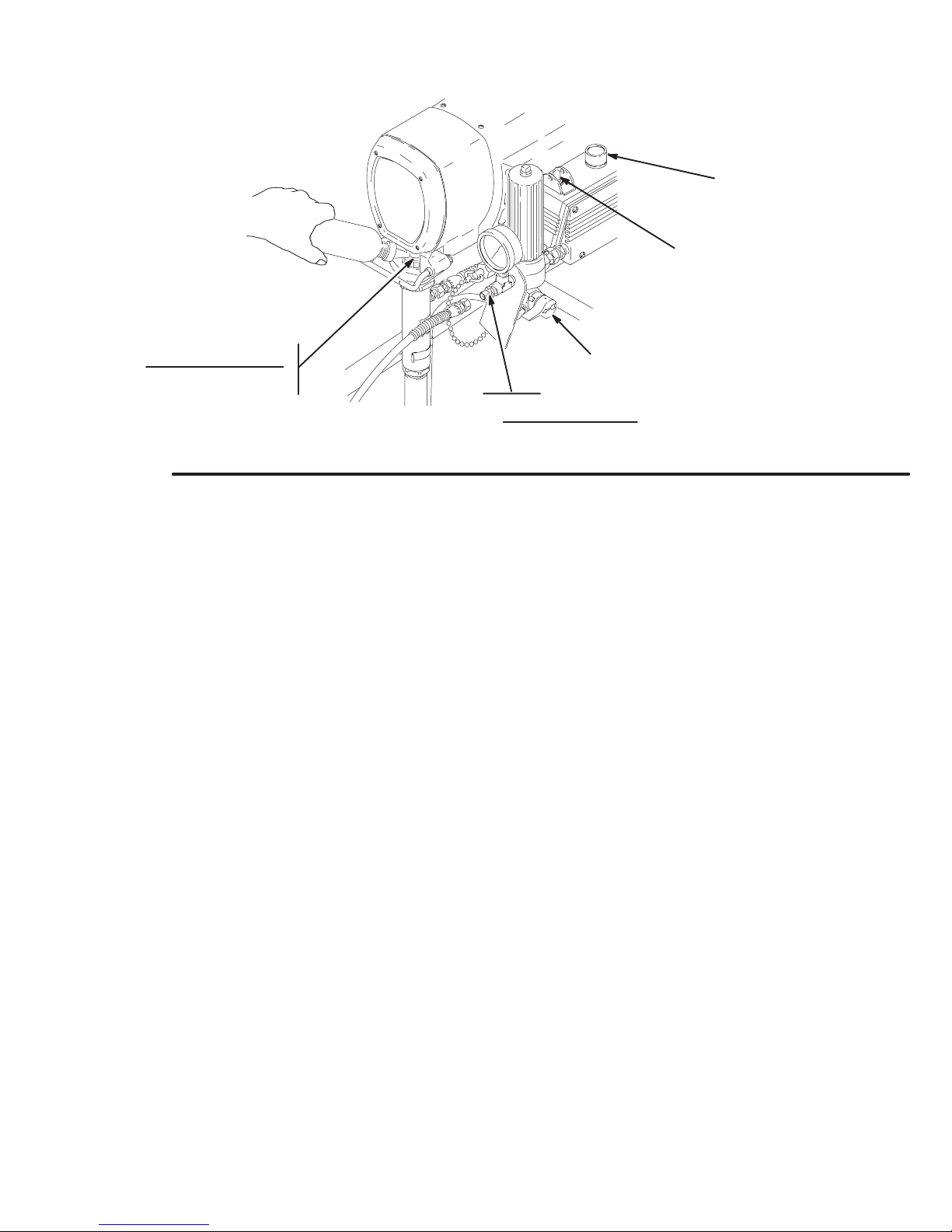
Page 7
Setup
PRESSURE ADJUSTING KNOB
ON/OFF SWITCH
PACKING NUT/ WET–CUP
FILL 1/3 FULL WITH TSL
Fig. 2
PRESSURE
DRAIN
VALV E
1/4 npsm(m) FLUID OUTLET NIPPLE
DO NOT INSTALL ANY SHUTOFF
DEVICE HERE
04787
7308-560
Page 8
Startup
Use this procedure each time you start the sprayer to
help ensure the sprayer is ready to operate and that you
start it safely.
WARNING
INJECTION HAZARD
To reduce the risk of serious injury,
follow the illustrated Pressure Relief
Procedure warning on page 12 when-
ever you are instructed to relieve pressure.
NOTE: Flush the sprayer if this is a first-time startup.
See page 11.
NOTE: See Fig. 4 except where noted.
1. Put the suction tube into the paint container .
2. Turn the pressure adjusting knob fully coun-
terclockwise to zero pressure.
3. Plug in the sprayer.
CAUTION
c. Release the trigger. Engage the gun safety latch.
5. Check all fluid connections for leaks . Relieve
the fluid pressure before tightening connections.
6. Install the spray tip and tip guard. Engage the
gun safety latch. See Fig. 3. Install the spray tip
according to the instructions supplied with it.
7. Adjust the spray pattern.
a. Increase the pressure just until spray from the
gun is completely atomized. Use the lowest
pressure needed to get the desired results. This
reduces overspray and fogging, decreases tip
wear and extends the life of the sprayer.
b. If more coverage is needed, use a larger tip
rather than increasing the pressure.
c. Test the spray pattern. T o adjust the pattern,
engage the gun safety latch, loosen the retaining
nut. Position the tip guard horizontally for a horizontal pattern or vertically for a vertical pattern.
Then tighten the retaining nut.
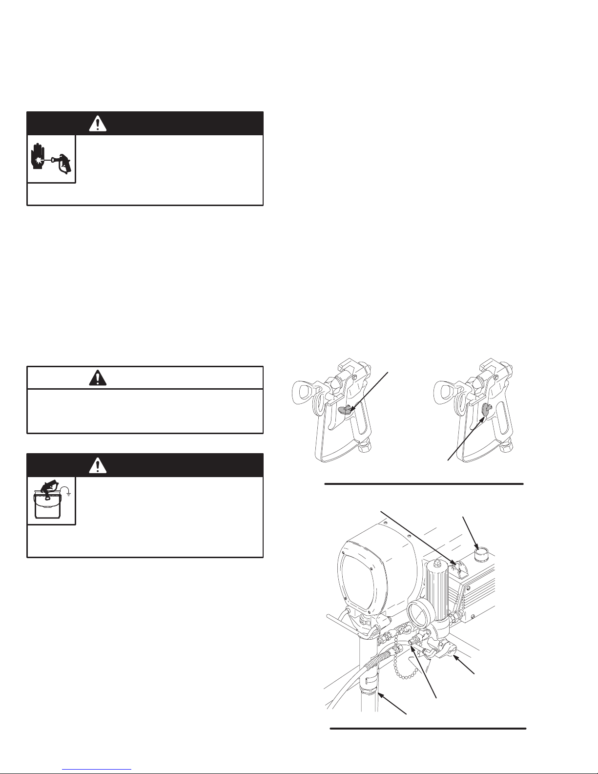
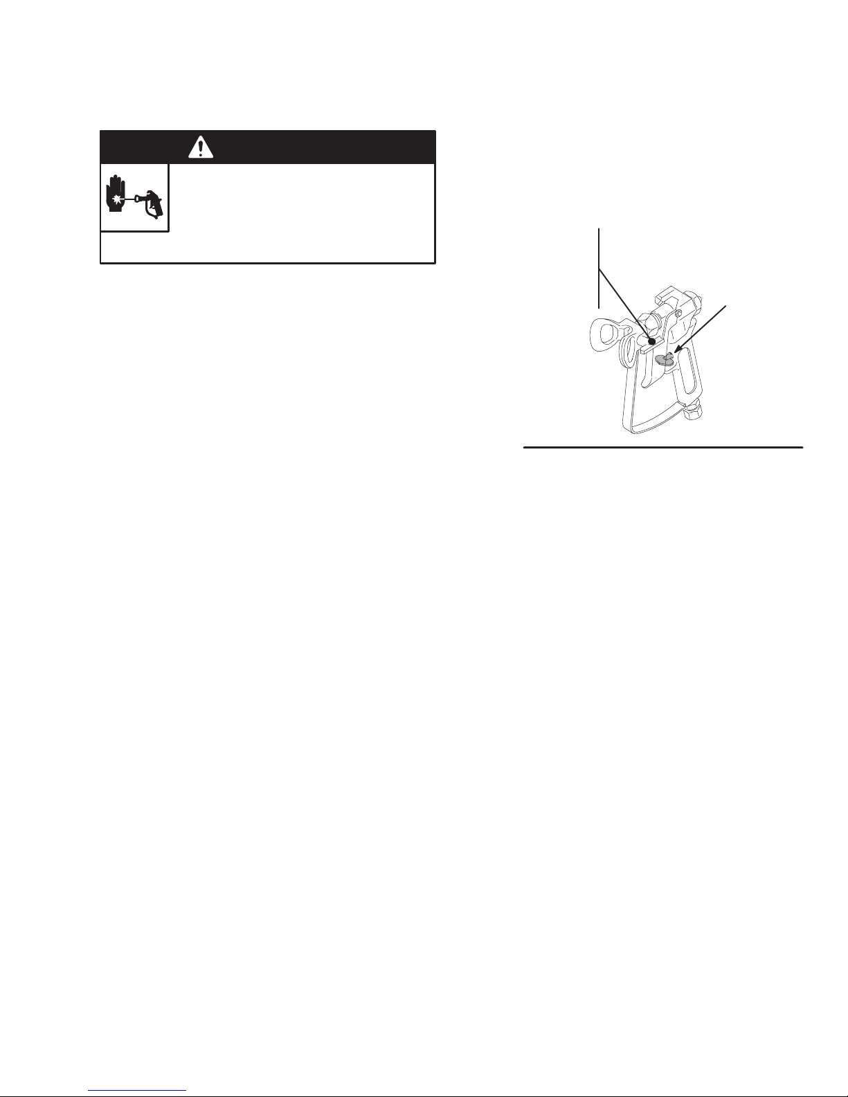
GUN SAFETY
LATCH SHOWN
ENGAGED
Do not run the pump without fluid in it for more than
30 seconds to avoid damage to the displacement
pump packings.
WARNING
FIRE AND EXPLOSION HAZARD
To reduce the risk of static sparking and
splashing when flushing, always remove
the spray tip from the gun and hold a
metal part of the gun firmly to the side of a
grounded metal pail.
4. Prime the pump.
a. Open the pressure drain valve (handle in down-
ward position). If you did not install a secondary
hose, be sure the nipple is tightly plugged with
the cap provided. Turn the ON/OFF switch to
ON. Slowly turn the pressure adjusting knob
clockwise until the sprayer starts. When fluid
comes from the drain hose, close the valve (handle in forward position).
b. Disengage the gun safety latch. See Fig. 3.
Following the warning, above, trigger the gun
until all air is forced out of the system and the
paint flows freely from the gun.
Fig. 3
ON/OFF SWITCH
Fig. 4
GUN SAFETY LATCH
SHOWN DISENGAGED
PRESSURE ADJUSTING KNOB
OUTLET NIPPLE
DRAIN HOSE
0137
PRESSURE
DRAIN
VALV E
04788
Page 9
Startup
Cleaning a Clogged Tip
WARNING
FLUID INJECTION HAZARD
To reduce the risk of serious injury,
follow the illustrated Pressure Relief
Procedure warning on page 12 when-
ever you are instructed to relieve pressure.
1. Clean the front of the tip frequently during the day’s
operation. First, relieve pressure.
2. If the spray tip does clog, release the gun trigger, engage the gun safety latch, and rotate the RAC IV
handle 180. See Fig. 5.
3. Disengage the gun safety latch and trigger the gun
into a waste container. Engage the gun safety latch
again.
4. Return the handle to the original position, disengage
the gun safety latch, and resume spraying.
5. If the tip is still clogged, engage the gun safety latch,
shut off and unplug the sprayer, and open the pressure drain valve to relieve pressure. Clean the spray
tip as shown on the RAC IV package.
TIP GUARD HANDLE
SHOWN IN SPRAYING
TURN HANDLE 180,
DISENGAGE SAFETY
LATCH AND TRIGGER
GUN TO CLEAR CLOG
Fig. 5
POSITION
GUN SAFETY
LATCH SHOWN
ENGAGED
0137
9308-560
Page 10
Shutdown and Care
WARNING
FLUID INJECTION HAZARD
To reduce the risk of serious injury,
follow the illustrated Pressure Relief
Procedure warning on page 12 when-
ever you are instructed to relieve pressure.
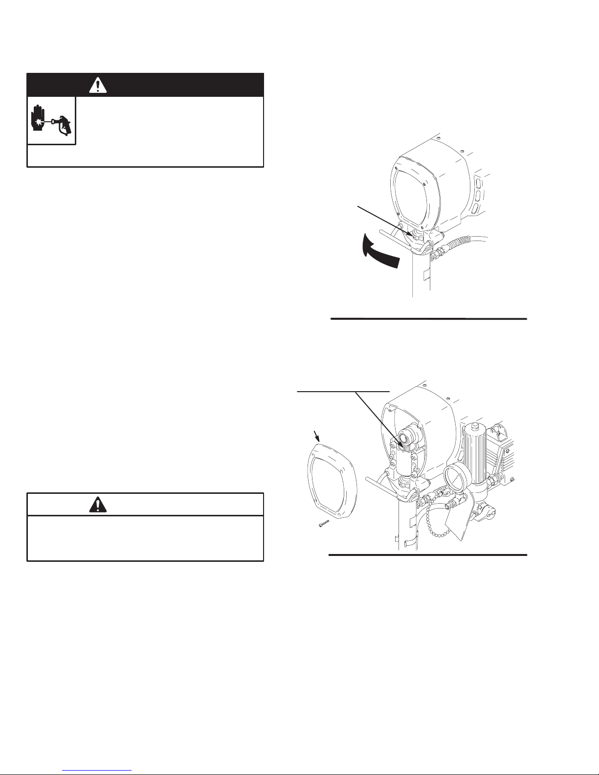
1. Check the packing nut/wet-cup daily. First relieve
pressure. Keep the wet-cup 1/3 full of TSL at all times
to help prevent fluid buildup on the piston rod and
premature wear of packings.
Tighten the packing nut just enough to stop leakage.
Over tightening causes binding and excessive packing wear. Use a round punch or brass rod and light
hammer to adjust the nut. Refer to Fig. 6.
6. Coil the hose and hang it on the hose rack when
storing it, even for overnight, to help protect the hose
from kinking, abrasion, coupling damage, etc.
PACKING NUT/
WET–CUP
TIGHTEN
2. Clean the fluid filter often and whenever the spray-
er is stored. Follow the Flushing Guidelines on page
11 or refer to manual 307–273, supplied, for the
cleaning procedure.
3. Lubricate the bearing housing after every 100
hours of operation. First relieve pressure. Remove
the front cover . Fill the bearing housing cavity with
SAE 10 non-detergent oil. See Fig. 7.
4. For very short shutoff periods, leave the suction
tube in the paint, relieve pressure, and clean the
spray tip.
5. Flush the sprayer at the end of each work day and
fill it with mineral spirits to help prevent pump corrosion and freezing. See page 11.
CAUTION
To prevent pump corrosion, never leave water or any
type of paint in the sprayer when it is not in use. Pump
water or paint out with mineral spirits.
Fig. 6
FILL BEARING HOUSING
CAVITY WITH SAE 10
NON-DETERGENT OIL
AFTER EVERY 100
HOURS OF OPERATION
FRONT
COVER
Fig. 7
01218A
04797
10 308-560
Page 11
Flushing
NOTE: Several flushes are often required to thoroughly clean the system and prepare it for the next fluid to be
sprayed, or to store the sprayer. Use this chart to determine the required flushing order for the fluid you are
using, and then follow the procedure below for flushing.
*Use this category for flushing a brand new sprayer and flushing after storage.
System has
this fluid in it: sprayed.
*Oil-based
solvent or paint
Oil-based
solvent or paint
Oil-based
solvent or paint
Water or waterbased paint
Water or waterbased paint
Water or waterbased paint
Next fluid to be
p
Oil-based paint –
new color
Water-based paint Mineral spirits Warm soapy
Prepare for
storage
Water-based paint
– new color
Oil-based paint Warm soapy
Prepare for
storage
Flush 1 Flush 2 Flush 3
Mineral spirits none none Prime with oil-based paint
Mineral spirits none none Relieve pressure,
Warm soapy
water
water
Warm soapy
water
WARNING
FIRE AND EXPLOSION HAZARD
To reduce the risk of static sparking and
splashing when flushing, always remove
the spray tip from the gun and hold a
metal part of the gun firmly to the side of a
grounded metal pail.
Flushing order:
Clean water Prime with water-based
water
Clean water none Prime with water
Clean water Mineral spirits Prime with oil
Clean water Mineral spirits Relieve pressure,
6. Do not run the pump dry for more than 30 seconds
to avoid damaging the pump packings!
7. Follow the illustrated Pressure Relief Procedure
on page 12. Engage the gun safety latch.
8. Unscrew the filter bowl and reinstall the clean
screen. Install the bowl and hand tighten.
Before you spray or store
p
sprayer:
paint
Leave drain valve open
Leave drain valve open
1. Follow the illustrated Pressure Relief Procedure
on page 12. Engage the gun safety latch.
2. Turn the pressure adjusting knob fully counterclockwise to zero pressure.
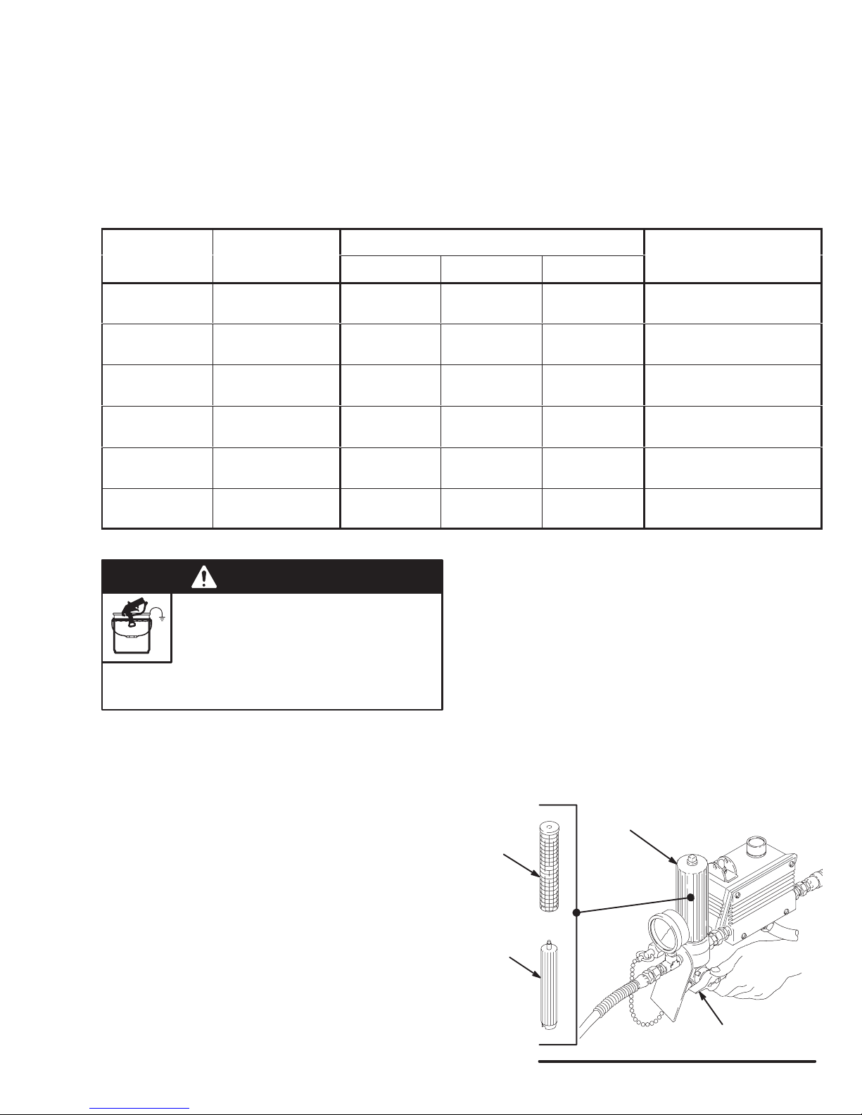
3. Remove the spray tip from the gun. Remove the
filter bowl and screen; see manual 307–273. Clean
the screen separately and install the bowl without
the screen to flush it. See Fig. 8.
4. Put the suction tube into a grounded metal pail
with 1/2 gallon of compatible solvent.
5. Start the sprayer. See page 8. To save the fluid
still in the sprayer, trigger the gun into another
container until the next fluid appears, then trigger
the gun back into the fluid you are pumping. Circulate the flushing fluid a couple of minutes to thoroughly clean the system.
9. Remove the suction tube and screen and clean
them separately.
FILTER
BOWL
SCREEN
FILTER
SUPPORT
PRESSURE
DRAIN VALVE
Fig. 8
04789
11308-560
Page 12
Troubleshooting
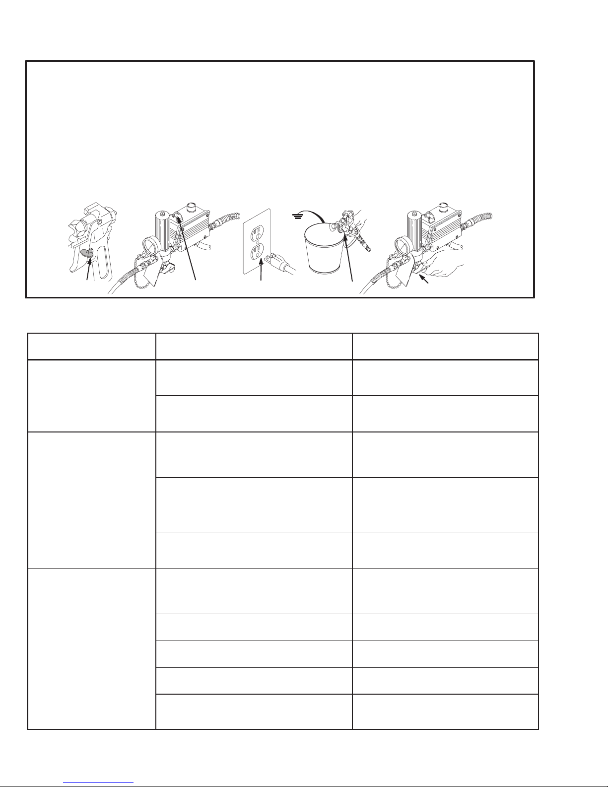
Pressure Relief Procedure
To reduce the risk of serious bodily injury, including fluid injection, splashing fluid or solvent in the eyes or on the skin,
or injury from moving parts or electric shock, always follow
this procedure whenever you shut of f the sprayer, when
checking or servicing any part of the spray system, when installing, cleaning or changing spray tips, and whenever you
stop spraying.
1. Engage the gun safety latch.
2. Turn the ON/OFF switch to OFF.
3. Unplug the power supply cord.
1,5 2 4
Perform all Troubleshooting procedures before disassembling the sprayer.
MOTOR WON’T OPERATE
TYPE OF PROBLEM
WHAT TO CHECK
If check is OK, go to next check
4. Disengage the gun safety latch. Hold a metal part of the
gun firmly to the side of a grounded metal pail, and trigger the gun to relieve pressure.
5. Engage the gun safety latch.
6. Open the pressure drain valve, having a container
ready to catch the drainage. Leave the valve open until
you are ready to spray again.
If you suspect that the spray tip or hose is completely
clogged, or that pressure has not been fully relieved after following the steps above,
retaining nut or hose coupling to relieve pressure gradually,
then loosen completely. Now clear the tip or hose.
3
VERY SLOWLY loosen the tip guard
6
WHAT TO DO
When check is not OK refer to this column
04793
Basic Fluid Pressure Problems
Basic Mechanical Problems 1. Check for frozen or hardened paint in the
Basic Electrical Problems
1. Check the pressure control knob setting. The
motor will not run if it is at the minimum setting
(fully counterclockwise).
2. Check for a clogged spray tip or fluid filter. Refer to the separate gun, tip, or fluid filter instruction manual.
pump (76) and/or pressure control tube. Using
a screwdriver, carefully try to rotate fan at back
of motor by hand. See page 17.
2. Check displacement pump connecting rod pin
(43). It must be completely pushed into connecting rod (68) and retaining spring (42) must
be firmly in groove of connecting rod. See Fig.
32.
3. Check for motor damage. Remove drive
housing assembly (67). See page 25. T ry to
rotate fan by hand.
1. Check pressure control safety circuit. 2. Turn pressure control ON/OFF switch to
2. Check electrical supply with volt meter. Meter
should read 200–250 VAC.
3. Check extension cord fordamage. Check extension cord continuity with a volt meter.
1. Slowly increase the pressure setting to see
if the motor starts.
2. Relieve pressure, refer to the separate gun,
tip, or fluid filter instruction manual for
cleaning.
1. Thaw. Plug in sprayer and turn on. Slowly
increase pressure setting to see if motor
starts. If it doesn’t, see NOTE 1, below.
2. Push pin into place and secure with spring
retainer.
3. Replace motor (73) if fan won’t turn. See
page 27.
OFF to RESET. If the pressure control safety continues to trip, see ELECTRICAL
SHORT on page 16.
2. Reset building circuit breaker; replace
building fuse. Try another outlet.
3. Replace extension cord.
4. Check sprayer power supply cord (314) for
damage such as broken insulation or wires.
5. Check motor brush leads, terminals and brush
length. Brush length should be 1/2” (12 mm)
minimum. See page 19.
NOTE 1: Thaw the sprayer if water or water-based paint has frozen in it, due to exposure to low temperatures, by placing it in a warm
area. Do not try to start the sprayer until it has thawed completely. If paint hardened (dried) in the sprayer, the pump packings and/or
pressure control must be replaced. See page 29 (Displacement Pump) or 22 (Pressure Control).
4. Replace power supply cord. See page 20.
5. Tighten terminal screws; replace brushes.
See page 19.
12 308-560
Page 13

MOTOR WON’T OPERATE (Continued)
TYPE OF PROBLEM
Follow Pressure Relief Procedure on page 13. Remove gun
from hose. Remove pressure
control.
WHAT TO CHECK
If check is OK, go to next check
1.Check leads from motor to be sure they are
securely fastened and properly mated.
2. Check for loose motor brush lead connections
and terminals. See page 19.
3. Check brush length which should be 12 mm
(1/2 in.) minimum. See page 19.
NOTE: The brushes do not wear at the same
rate on both sides of the motor . Check both
brushes.
4. Check for broken or misaligned motor brush
springs. Rolled portion of spring must rest
squarely on top of brush. See page 19.
5. Check motor brushes for binding in brush
holders. See page 19.
6. Check motor armature commutator for burn
spots, gouges and extreme roughness. Remove motor cover and brush inspection
plates to check. See page 19.
WHAT TO DO
When check is not OK refer to this column
1. Replace loose terminals; crimp to leads. Be
sure male terminal blades are straight and
firmly connected to mating part.
Clean circuit board male terminals. Replace loose or damaged terminals. Securely reconnect leads.
2. Tighten terminal screws. Replace brushes
if leads are damaged. See page 19.
3. Replace brushes. See page 19.
4. Replace spring if broken. Realign spring
with brush. See page 19.
5. Clean brush holders. Remove carbon with
small cleaning brush. Align brush leads
with slot in brush holder to assure free vertical brush movement.
6. Remove motor and have motor shop resurface commutator if possible. See page 27.
Refer to the wiring diagram on
page 38 to identify test points
(TP).
7. Check motor armature for shorts using armature tester (growler) or perform spin test. See
page 17.
8. Check pressure control board (301) by substituting with a good pressure control board. See
page 22.
1. Check filter board. Connect volt meter to TP7
and ON/Off switch TP3.Connect a jumper
from TP4 to TP8. Plug in sprayer . Meter
should read 200 to 250 VAC. Unplug sprayer.
Remove jumper.
2. Check power supply cord (314). Disconnect
TP1 female (neutral) and TP2 female and
connect volt meter to these leads. Plug in
sprayer. Meter should read 200 to 250 VAC.
Unplug sprayer. Reconnect TP2.
3. Check ON/OFF switch (307). Disconnect TP3
and TP4 and connect volt meter to TP3 and
TP4 terminal on the ON/OFF switch. Plug in
sprayer and turn ON. Meter should read 200
to 250 VAC. Turn off and unplug sprayer. Reconnect TP3.
4. Check motor terminal cutoff switch. Connect
volt meter to TP1 female and TP6 female.
Plug in sprayer and turn on. Meter should read
200 to 250 VAC. Turn off and unplug sprayer.
5. Check all terminals for damage or loose fit.
Reconnect TP1, TP2, TP3, TP4, TP5, and
TP6 connectors.
7. Replace motor. See page 27.
8. Replace with new pressure control board
(301). See page 22.
1. Temporary bypass to check (Replace filter
board?)
2. Replace power supply cord. See page 20.
3. Replace ON/OFF switch. See page 21.
4. Allow motor to cool. Correct cause of overheating. If switch remains open after motor
cools, check continuity between TP4 female and TP5 female with ohmmeter . If
open, replace motor.
5. Replace damaged terminals and reconnect securely.
13308-560
Page 14

LOW OUTPUT
TYPE OF PROBLEM
Low Output
WHAT TO CHECK
If check is OK, go to next check
1. Check for worn spray tip. 1. Follow Pressure Relief Procedure Warn-
2. Check to see that pump does not continue to
stroke when gun trigger is released. Plug in
and turn on sprayer. Prime with paint. Trigger
gun momentarily, then release and engage
safety latch. Relieve pressure, turn off and unplug sprayer.
3. Check electrical supply with volt meter. Meter
should read 200–250 VAC.
4. Check extension cord size and length; must
be at least 1.5 mm
longer than 100m (300 ft).
5. Check +, –, M+ and M– leads from motor to
pressure control circuit board (B1) for damaged or loose wires or connectors. Inspect
wiring insulation and terminals for signs of
overheating. See page 27.
6. Check for loose motor brush leads and terminals. See page 19.
7. Check for worn motor brushes which should
be 12 mm (1/2 in.) minimum. See page 19.
2
(12 AWG) wire and no
WHAT TO DO
When check is not OK refer to this column
ing then replace tip. See your separate gun
or tip manual.
2. Service pump. See pages 29–33.
3. Reset building circuit breaker; replace
building fuse. Repair electrical outlet or try
another outlet.
4. Replace with a correct, grounded extension cord.
5. Be sure male terminal blades are centered
and firmly connected to female terminals.
Replace any loose terminal or damaged
wiring. Securely reconnect terminals.
6. Tighten terminal screws. Replace brushes
if leads are damaged. See page 19.
7. Replace brushes. See page 19.
8. Check for broken and misaligned motor brush
springs. Rolled portion of spring must rest
squarely on top of brush.
9. Check motor brushes for binding in brush
holders. See page 19.
10.Check stall pressure. Gauge should read 170
bar (2500 psi) minimum.
11. Check pressure control board (301) by substituting with a good pressure control board. See
page 22.
12.Check motor armature for shorts by using an
armature tester (growler) or perform spin test.
See page 17.
8. Replace spring if broken. Realign spring
with brush. See page 19.
9. Clean brush holders, remove carbon dust
with small cleaning brush. Align brush lead
with slot in brush holder to assure free vertical brush movement.
10.Replace with new pressure control board
(301). See page 22.
11. Replace with new pressure control board
(301). See page 22.
12.Replace motor. See page 27.
14 308-560
Page 15

NO OUTPUT
TYPE OF PROBLEM
WHAT TO CHECK
If check is OK, go to next check
Motor runs and pump strokes 1. Check paint supply. 1. Refill and reprime pump.
2. Check for clogged intake strainer. 2. Remove and clean, then reinstall.
3. Check for loose suction tube or fittings. 3. Tighten; use thread sealant or sealing tape
4. Check to see if intake valve ball and piston ball
are seating properly. See page 29.
5. Check for leaking around throat packing nut
which may indicate worn or damaged packings. See page 29.
Motor runs but pump does not
stroke
1. Check displacement pump connecting rod pin
(43). See page 32.
2. Check connecting rod assembly (68) for damage. See page 24.
3. Be sure crank in drive housing rotates; plug in
sprayer and turn on briefly to check. Turn off
and unplug sprayer. See page 25.
WHAT TO DO
When check is not OK refer to this column
on threads if necessary.
4. Remove intake valve and clean. Check
balls and seats for nicks; replace if necessary. See page 29. Strain paint before using to remove particles that could clog the
pump.
5. Replace packings. See pages 29–33. Also
check piston valve seat for hardened paint
or nicks and replace if necessary. Tighten
the packing nut/wet-cup.
1. Replace pin if missing. Be sure retainer
spring (42) is fully in groove all around connecting rod. See page 32.
2. Replace connecting rod assembly . See
page 24.
3. Check drive housing assembly for damage
and replace if necessary. See page 25.
EXCESSIVE PRESSURE FLUCTUATIONS
TYPE OF PROBLEM
Spray pattern variations. 1. Be sure leads to pressure control circuit board
WHAT TO CHECK
If check is OK, go to next check
(B1) are firmly connected. Be sure all male terminals blades are centered and firmly connected to female terminals. See Fig. 33.
2. Check maximum working pressure. 2. Replace with a new pressure control board
3. Check pressure control board (301) by substituting with a good pressure control board. See
page 22.
4. Check LOW OUTPUT section, page 14.
WHAT TO DO
When check is not OK refer to this column
1. Reconnect securely. See Fig. 33.
(301). See page 22.
3. Replace with a new pressure control board
(301). See page 22.
15308-560
Page 16

MOTOR IS HOT AND RUNS INTERMITTENTLY
TYPE OF PROBLEM
Motor is hot and runs intermittently.
ELECTRICAL SHORT
TYPE OF PROBLEM
Building circuit breaker opens
as soon as sprayer switch is
turned on.
WHAT TO CHECK
If check is OK, go to next check
1. Determine if sprayer was operated at high
pressure with small tips, which causes low
motor RPM and excessive heat build up.
2. Be sure ambient temperature where sprayer
is located is no more than 32
sprayer is not located in direct sun.
3. Determine if sprayer was turned on, pressurized, but not operating for long periods of time.
WHAT TO CHECK
C(90F) and
If check is OK, go to next check
1. Check all electrical wiring for damaged insulation, and all terminals for loose fit or damage.
Also check wires between pressure control
and motor which are encased in conduit (1).
See page 27.
2. Check for missing inspection plate gasket
(see page 27), bent terminal forks or other
metal to metal contact points which could
cause a short.
3. Check motor armature for shorts. Use an armature tester (growler) or perform spin test.
See page 17. Inspect windings for burns.
WHAT TO DO
When check is not OK refer to this column
1. Decrease pressure setting or increase tip
size.
2. Move sprayer to shaded, cooler area if possible.
3 Turn off sprayer whenever you stop spray-
ing for a while and relieve fluid pressure.
WHAT TO DO
When check is not OK refer to this column
1. Repair or replace any damaged wiring or
terminals. Securely reconnect all wires.
2. Correct faulty conditions.
3. Replace motor. See page 27.
Sprayer quits after sprayer operates for 5 to 10 minutes.
4. Check pressure control board (301) by substituting with a good control board. See page 22.
1. Check Basic Electrical Problems on page 12. 1. Perform necessary procedures.
2. Check ON/OFF switch (307) See page 21.
sure the sprayer is unplugged!
wires from switch. Check switch with ohmmeter. The reading should be infinity with the ON/
OFF switch OFF, and zero with the switch ON.
3. Check for damaged or pinched wires in the
pressure control. See page 22.
1. Check Basic Electrical Problems on page 12. 1. Perform necessary procedures.
2. Check electrical supply with volt meter. Meter
should read 200 to 250 VAC.
3. Check tightness of pump packing nut. Overtightening tightens packings on rod, restricts
pump action, and damages packings.
Disconnect
4. Replace with a new pressure control board
(301). See page 22.
Be
2. Replace ON/OFF switch. See page 21.
3. Replace damaged parts. See page 22.
2. If voltage is too high, do not operate
sprayer until corrected.
3. Loosen packing nut. Check for leaking
around throat. Replace pump packings, if
necessary. See page 29.
16 308-560
Page 17

WARNING
ELECTRIC SHOCK HAZARD
Do not touch the brushes, leads, springs
or brush holders while the sprayer is
plugged in to reduce the risk of electric
shock and serious bodily injury.
WARNING
INJECTION HAZARD
To reduce the risk of serious injury,
follow the illustrated Pressure Relief
Procedure warning on page 12 when-
ever you are instructed to relieve pressure.
Spin Test
lutions before coming to a complete stop. If the motor
does not spin freely, the armature is shorted and the motor must be replaced. See page 27.
59
F
For checking armature, motor winding and brush electrical continuity.
Setup
Relieve pressure. Remove the drive housing. See page
25.
Remove the motor shield (59), the fan cover (F) and the
inspection covers (J). See Fig. 9.
Remove the pressure control/cover(301). Disconnect
the – and + leads from the motor to the pressure control/
cover terminals M–, and M+. See Fig. 10.
Armature Short Circuit Test
Relieve pressure. Quickly turn the motor fan by hand. If
there are no shorts, the motor will coast two or three revo-
301
Fig. 9
J
01224A
Armature, Brushes, and Motor Wiring Open
Circuit Test (Continuity)
Relieve pressure. Connect the two black motor leads together with a test lead. Turn the motor fan by hand at
about two revolutions per second.
If there is uneven or no turning resistance, check the following: broken brush springs, brush leads, motor leads;
loose brush terminal screws, motor lead terminals; worn
brushes. Repair parts as needed. See page 19.
If there is still uneven or no turning resistance, replace the
motor. See page 27.
Fig. 10
M–
–
M+
+
04790
Page 18

General Repair Information
CAUTION
To reduce the risk of a pressure control malfunction:
Always use needle nose pliers to disconnect a
wire. Never pull on the wire, pull on the connector.
Mate wire connectors properly. Be sure the flat
blade of the insulated male connector is centered
in the wrap-around blade of the female connector.
Route wires carefully to avoid interference with
the other connections of the pressure control. Be
sure the wires are not pinched between the cover
and the control box.
Tool List
Phillips screwdriver
Small flat blade
screwdriver
Needle nose pliers
Plastic mallet
Adjustable wrench
Adjustable, open-end
wrench
Torque wrench
1/4 in. hex key wrench
3/16 in. hex key wrench
5/8 in. socket wrench
3/8 in. open end wrench
1/2 in. open end wrench
3/4 in. open end wrench
7/8 in. open end wrench
High quality motor oil
Bearing grease
WARNING
ELECTRIC SHOCK HAZARD
To reduce the risk of serious injury, including electric shock, DO NOT touch
any moving parts or electrical parts with
your fingers or a tool while inspecting the repair.
Shut off the sprayer and unplug it as soon as you
complete the inspection. Reinstall all covers, gaskets, screws and washers before operating the
sprayer.
3. If the sprayer does not operate properly, review
the repair procedure again to verify that everything
was done correctly. If necessary, see the
Troubleshooting Guide, pages 12 – 16, to help
identify other possible problems and solutions.
CAUTION
Do not run the sprayer dry for more than 30 seconds to avoid damaging the pump packings.
4. Reinstall the motor shield before regular op-
eration of the sprayer and replace it if it is damaged. The cover directs cooling air around the
motor to help prevent overheating. It can also help
reduce the risk of burns, fire or explosion; see the
WARNING, below.
1. Keep all screws, nuts, washers, gaskets, and
electrical fittings removed during repair procedures. These parts are not normally provided with
replacement assemblies.
2. Test your repair before regular operation of the
sprayer to be sure the problem is corrected.
WARNING
FIRE AND EXPLOSION HAZARD
During operation, the motor and drive
housing become very hot and could
burn your skin if touched. Flammable
materials spilled on the hot, bare motor could
cause a fire or explosion. Always have the motor
shield in place during regular operation to reduce
the risk of burns, fire or explosion.
18 308-560
Page 19

Motor Brush Replacement
NOTE: Replace the brushes when they have worn to
less than 12 mm (1/2 in). Note that the brushes
wear differently on each side of the motor , so
check them both. Brush Repair Kit 222–157 is
available. A new spring clip, P/N 1 10–816 may
be purchased separately.
WARNING
INJECTION HAZARD
To reduce the risk of serious injury,
follow the illustrated Pressure Relief
Procedure warning on page 12 when-
ever you are instructed to relieve pressure.
NOTE: Read the GENERAL REP AIR INFORMATION
on page 18 before doing this procedure.
1. Relieve pressure.
2. Remove the motor shield (59). Remove the inspection covers (J) and gaskets (K) on each side
of the motor. See Fig. 11.
5. Inspect the commutator for excessive pitting,
burning or gouging. A black color on the commutator is normal. Have the commutator resurfaced by
a qualified motor repair shop if the brushes seem
to wear too fast.
CAUTION
When installing the brushes, follow all steps carefully to avoid damaging the parts.
6. Install a new brush so the lead is in the long slot of
the holder. See Fig. 13.
BRUSH HOLDER
SHORT SLOT
LONG SLOT
BRUSH
SPRING
CLIP
59
F
Fig. 11
J
01224A
3. Push in the spring clip to release its hooks from
the brush holder. Pull out the spring clip. See Fig.
12.
SPRING
HOOK
BRUSH
SPRING CLIP
P/N 110–816
Fig. 12
4. Loosen the brush lead terminal screw. Pull the
brush lead away, leaving the motor lead terminal in
place. Remove brush and spring. See Fig. 14.
01227
NOTE: SPRING MUST COIL
IN THIS DIRECTION
Fig. 13
01227
7. Slide the terminal under the terminal screw washer
and tighten the screw. Be sure the motor lead is
still connected at the screw. See Fig. 14.
SPRING
BRUSH
Fig. 14
TERMINAL SCREW
MOTOR LEAD
TERMINAL
SPRING CLIP
BRUSH LEAD
01227
8. Place the spring on the brush as shown in Fig. 13.
9. Install the spring clip and push it down to hook the
short slots in the housing. See Fig. 13.
10. Repeat for the other side.
Page 20

11. Test the brushes.
a. Remove the pump connecting rod pin.
b. With the sprayer OFF, turn the pressure con-
trol knob fully counterclockwise to minimum
pressure. Plug in the sprayer.
c. Turn the sprayer ON. Slowly increase the
pressure until the motor is at full speed.
d. Inspect the brush and commutator contact
area for excessive arcing. Arcs should not
“trail” or circle around the commutator surface.
WARNING
ELECTRIC SHOCK HAZARD
Do not touch the brushes, leads, springs
or brush holders while the sprayer is
plugged in to reduce the risk of electric
shock and serious bodily injury.
CAUTION
Do not run the sprayer dry for more than 30
seconds while checking the brushes to avoid
damaging the displacement pump packings.
12. Install the brush inspection covers and gaskets.
13. Break in the brushes. Operate the sprayer for at
least one hour with no load. Install the connecting
rod pin.
Power Supply Cord Replacement (Fig. 15)
WARNING
INJECTION HAZARD
To reduce the risk of serious injury,
follow the illustrated Pressure Relief
Procedure warning on page 12 when-
ever you are instructed to relieve pressure.
NOTE: Read the GENERAL REPAIR INFORMATION
on page 18 before doing this procedure.
1. Relieve pressure.
2. Remove the pressure control board/cover (301).
3. Disconnect the power supply cord (314),
both leads from the ON/OFF switch (307), and
the green wire to the grounding screw (317).
4. Loosen the strain relief bushing (315) and remove
the power supply cord (314).
5. Install the new power supply cord in the reverse
order.
301
307
317
315
6. Install the proper plug on the other end of the
power supply cord. Follow all local codes to select
the proper plug.
Fig. 15
20 308-560
314
04791
Page 21

On/Off Switch Replacement (Fig. 16)
WARNING
FLUID INJECTION HAZARD
To reduce the risk of serious injury,
follow the illustrated Pressure Relief
Procedure warning on page 12 when-
ever you are instructed to relieve pressure.
NOTE: Read the GENERAL REP AIR INFORMATION
on page 18 before doing this procedure.
1. Relieve pressure.
2. Remove the pressure control board/cover (301).
3. Disconnect the two wires from the ON/OFF switch
(307). See Fig. 15.
8. Powder the inside of the rubber boot (309) with
talcum powder, then shake the excess out of the
boot.
9. Install the nut and rubber boot and tighten.
10. Reconnect all wires.
309
308
4. Using a 5/8 in. socket wrench, remove the nut and
rubber boot (309). Remove the switch guard (308).
See Fig. 16.
5. Remove the ON/OFF switch (307).
6. Install the new switch so the internal tab of the
pressure control housing (D) engages with the
vertical groove in the threads of the switch.
7. Install the switch guard (308), aligning the internal
tab with the groove in the threads.
Fig. 16
D
307
04795
21308-560
Page 22

Pressure Control Replacement
WARNING
FLUID INJECTION HAZARD
To reduce the risk of serious injury,
follow the illustrated Pressure Relief
Procedure warning on page 12 when-
ever you are instructed to relieve pressure.
3. Remove the four mounting screws and washers
(302, 303, 304) from the pressure control board/
cover (301). See Fig. 18.
4. Carefully remove the pressure control board/cover
(301) so as not to stress the cables.
5. Remove the potentiometer cable (310) from the
pressure control board/cover (301).
1. Relieve pressure.
2. Disconnect the filter/drain valve assembly and the
pump supply hose at the pressure control while
holding the pressure control fitting (A) firmly. See
the CAUTION, below. See Fig. 17.
CAUTION
Do not allow the fittings (A) to turn when removing
or connecting the hose and filter/drain assembly.
Do not over tighten the screws when attaching the
pressure control board/cover. Turning the fittings or
over tightening the screws may shift the calibration
of the pressure control.
6. Disconnect the pressure control board/cover
black/white M+ and black M– leads from the motor
+ and– leads.
7. Disconnect the red motor leads from the TS leads
on the pressure control board/cover (301).
8. Disconnect the brown power lead (L1) from the
filter board.
9. Disconnect the blue lead (L2) from the filter board.
10. Loosen the ground terminal screw (317) and
disconnect the ground lead (C).
11. Pull off the pressure control board/cover.
TO PUMP
TO GUN
Fig. 17
22 308-560
A
301
A
FILTER/DRAIN
VALVE ASSEMBLY
04792
Page 23

Pressure Control Replacement
WARNING
Do not attempt to adjust or calibrate the pressure
control. If the pressure control is faulty, replace it.
301
12. Reassemble in the reverse order; attach ground
wire (C), power leads (L1 and L2), the red leads to
the TS terminals on the circuit board (B1), the M+
and M– leads, and the potentiometer cable to the
connector on B1. Carefully route the wires away
from the filter board. Attach the pressure control
board/cover (301) using the four mounting screws
and washers (302, 303, 304),
304
Fig. 18
303
302
304
310
TS
L2
L1
B1
C
317
04790
Filter Board Replacement
WARNING
FLUID INJECTION HAZARD
To reduce the risk of serious injury,
follow the illustrated Pressure Relief
Procedure warning on page 12 when-
ever you are instructed to relieve pressure.
1. Relieve pressure.
2. Perform the Pressure Control Replacement
procedure steps 2 through 11.
3. Remove the three screws holding the filter board in
place and remove the filter board.
4. Reassemble in the reverse order; replace filter
board, attach ground wire (C), power leads (L1
and L2), the red leads to the TS terminals on the
circuit board (B1), the M+ and M– leads, and the
potentiometer cable to the connector on B1. Carefully route the wires away from the filter board.
Attach the pressure control board/cover (301)
using the four mounting screws and washers (302,
303, 304),
23308-560
Page 24

Bearing Housing and Connecting Rod
Replacement (Fig. 19)
WARNING
FLUID INJECTION HAZARD
To reduce the risk of serious injury,
follow the illustrated Pressure Relief
Procedure warning on page 12 when-
ever you are instructed to relieve pressure.
NOTE: Read the GENERAL REP AIR INFORMATION
on page 18 before doing this procedure.
NOTE: Stop the sprayer at the bottom of its stroke to get
the crank (E) in its lowest position.To lower the
crank manually, carefully rotate the blades of the
fan with a screwdriver.
11. Align the connecting rod (68) with the crank (E)
and the drive housing locating pins (G) with the
bearing housing (69) holes. Push the bearing
housing onto the drive housing or tap it into place
with a plastic mallet.
CAUTION
DO NOT use the bearing housing screws (25) to try
to align or seat the bearing housing; the bearing and
drive housing will not align properly and will result in
premature bearing wear.
12. Install the screws and lockwashers (25,23). Tighten the screws evenly to 175 in-lb (19 N.m).
1. Relieve pressure.
2. Remove the front cover (49). Unclip the drain hose
(36) from the pump. Hold a wrench on the pump
intake valve (223) and unscrew the pump suction
tube. Disconnect the pump hose (70).
3. Push up the retaining spring (42). Push the pin
(43) out the rear.
4. Loosen the locknut (47). Unscrew the displacement pump (76).
5. Remove the four screws and lockwashers (25,23).
6. Lightly tap the lower rear of the bearing housing
(69) with a plastic mallet to loosen it from the drive
housing (67). Pull the bearing housing and the
connecting rod assembly (68) straight off the drive
housing.
7. Remove the pail bracket assembly (F) and install it
on the new bearing housing.
13. Install the pump. See page 32.
14. Install the remaining parts. See Fig. 19
67
PACK WITH
BEARING GREASE
B
OIL
25,23
TORQUE TO
175 in-lb (19 N.m)
49
F
C
68
42
47
43
E
40
.
G
69
70
8. Inspect the crank (E) for excessive wear and
replace parts as needed. Evenly lubricate the
inside of the bronze bearing (B) with high quality
motor oil. Liberally pack the roller bearing (C) with
bearing grease.
9. Assemble the connecting rod (68) and bearing
housing (69).
10. Clean the mating surfaces of the bearing and drive
housings (69,67).
24 308-560
Fig. 19
76
223
36
04486
Page 25

Drive Housing Replacement (Fig. 20)
WARNING
FLUID INJECTION HAZARD
To reduce the risk of serious injury,
follow the illustrated Pressure Relief
Procedure warning on page 12 when-
ever you are instructed to relieve pressure.
CAUTION
4. Lightly tap the lower rear of the bearing housing
(69) with a plastic mallet to loosen it from the drive
housing (67). Pull the assembled bearing housing
and connecting rod straight off the drive housing.
5. Remove the two drive housing screws (26) and
lockwashers (20).
6. Remove the two lower screws (13) and lockwashers (20) and then the two upper screws (16) and
lockwashers (20) from the front of the motor (73).
DO NOT drop the gear cluster (51) when removing
the drive housing (67). The gear cluster may stay engaged in the motor front end bell or the drive housing.
DO NOT lose the thrust balls (9) located at each end
of the gear cluster (51) or drop them between gears.
The balls, which are heavily covered with grease,
usually stay in the shaft recesses, but could be dislodged. If caught between gears and not removed,
the balls will seriously damage the drive housing. If
the balls are not in place, the bearings will wear prematurely.
NOTE: Read the GENERAL REP AIR INFORMATION
on page 18 before doing this procedure.
1. Relieve pressure.
2. Remove the front cover (49) and the motor shield
(59). Unclip the drain hose (36) from the pump.
3. Remove the four bearing housing screws (25) and
lockwashers (23).
7. Tap the drive housing (67) with a plastic mallet to
loosen it from the front of the motor (73), and then
pull the drive housing straight off.
8. Liberally apply bearing grease to the gear cluster
(51). The gear area should have approximately 4
total ounces of grease. Grease is supplied with
the drive housing replacement kit. Be sure the
thrust balls (9) are in place.
9. Place the bronze-colored washer (67b) THEN the
silver-colored washer (67a) on the shaft protruding
from the big gear in the drive housing (67).
10. Align the gears and push the new drive housing
straight onto the front of the motor and locating
pins.
11. Continue reassembling the sprayer.
25308-560
Page 26

Drive Housing Replacement
34
16
20
25,23
TORQUE TO
175 in-lb (19 N.m)
49
LIBERALLY APPLY GREASE
67b
67
69
36
9
59
67a
51
13
20
9
20
26
ig. 20
26 308-560
03752
Page 27

Motor Replacement (Fig. 21 and 22)
WARNING
FLUID INJECTION HAZARD
To reduce the risk of serious injury,
follow the illustrated Pressure Relief
Procedure warning on page 12 when-
ever you are instructed to relieve pressure.
12. Remove the two lower screws (13) and lockwashers (20) and then the two upper screws (16) and
lockwashers (20) from the front of the motor (73).
13. Tap the drive housing (67) with a plastic mallet to
loosen it from the front of the motor (73), and then
pull the drive housing straight off.
NOTE: Read the GENERAL REP AIR INFORMATION
on page 18 before doing this procedure.
1. Relieve pressure.
2. Remove the motor shield (59).
3. Remove the pressure control board/cover (301).
Disconnect the four motor leads. See figure 21.
4. Loosen the conduit connector nut on the conduit
connector (318) at the pressure control.
5. Swing the conduit (1) away from the conduit
connector (318).
6. Remove the conduit seal (29) from around the
conduit elbow coming into the pressure control.
Pull the motor leads through the elbow, one at a
time.
CAUTION
Always pull the motor leads one at a time to avoid
loosening the terminals, which could result in a bad
connection and poor sprayer performance.
CAUTION
DO NOT drop the gear cluster (51) when removing
the drive housing (67). The gear cluster may stay engaged in the motor front end bell or the drive housing.
DO NOT lose the thrust balls (9) located at each end
of the gear cluster (51) or drop them between gears.
The balls, which are heavily covered with grease,
usually stay in the shaft recesses, but could be dislodged. If caught between gears and not removed,
the balls will seriously damage the drive housing. If
the balls are not in place, the bearings will wear prematurely.
14. While supporting the motor (73) to keep the
sprayer from tipping, remove the four motor
mounting screws (8). Lift off the motor.
15. Install the new motor (73).
16. Liberally apply bearing grease to the gear cluster
(51). The gear area should have approximately 4
total ounces of grease, Grease is supplied with
the drive housing replacement kit. Be sure the
thrust balls (9) are in place.
7. Loosen the connector nut on the connector elbow
(31) at the motor and pull the conduit (1) away
from the motor. Pull the leads through the conduit,
one at a time.
8. Unscrew the connector elbow (31) from the
motor.
9. Pull the wires through the elbow, one at a time.
10. Remove the front cover (49).
11. Remove the two drive housing screws (26).
17. Place the bronze-colored washer (67b) and then
the silver-colored washer (67a) on the shaft protruding from the big gear in the drive housing (67).
18. Align the gears and push the drive housing (67)
straight onto the front of the motor (73) and locating pins.
19. Continue reassembling the sprayer. Use a turning
motion on the conduit (1) when feeding wires
through it. Install the conduit seal (29) around the
wires in the conduit elbow (318) at the pressure
control to keep contaminants from entering the
motor conduit. See the Detail in Fig. 22.
Page 28

B1
Motor Replacement
DETAIL
Shows position of
conduit seal (29) in
conduit connector (345)
Fig. 21
POWER CORD
LIBERALLY APPLY GREASE
67b
51
67a
M+
M–
MOTOR
73
9
29
+
–
04772
318
01232
34
59
16
20
49
Fig. 22
26
69
20
67
36
31
8
13
20
9
11
70
10
1
318
70
40
301
04804
28 308-560
Page 29

Displacement Pump Repair (Fig. 23, 24, 25
and 26)
WARNING
FLUID INJECTION HAZARD
To reduce the risk of serious injury,
follow the illustrated Pressure Relief
Procedure warning on page 12 when-
ever you are instructed to relieve pressure.
NOTE: Read the GENERAL REP AIR INFORMATION
on page 18 before doing this procedure.
NOTE: Use Packing Repair Kit 222–588. An asterisk
following a reference number, i.e., (210*), indicate that the part included in the kit. For the best
results, use all the new parts in the kit even if the
old ones still look good.
NOTE: Clean and inspect parts after disassembling the
pump. Replace worn or damaged parts.
Disassembling the Pump
1. See page 32 to remove the pump.
2. Unscrew the intake valve (223) from the cylinder
(219). Remove all parts. See Fig. 23.
205
216
224
219
Fig. 23
3. If no further service is needed, reassemble the
intake valve. Be sure you use a new o-ring (202*).
220
221*
204*
202*
223
INTAKE
VALV E
04230
4. Remove the packing nut (216) and plug (205). See
Fig. 23.
5. Use a plastic mallet to tap the piston rod (224)
down, then pull the rod out through the bottom of
the cylinder (219). See Fig. 23.
6. Remove the throat packings and glands. See Fig.
24.
*209
*213
THROAT
PACKINGS
*208
207*
219
Fig. 24
04231
Page 30

Displacement Pump Repair
7. Clamp the flats of the piston rod in a vise. Loosen
the retaining nut (211). Unscrew the piston valve
(222) from the rod. Remove all parts from the
piston valve (222). See. Fig 25.
210*
WARNING
Always use the special sleeve removal tool to remove the sleeve. Other removal methods could
cause the pump to rupture, resulting in serious bodily
injury. If the sleeve cannot be removed easily using
the tool, return the sleeve and cylinder to your Graco
distributor for removal.
9. Screw the large nut (B) of the tool into the top of
the cylinder (19). Screw down the rod (A) to push
the sleeve out. Remove the tool. See Fig. 26
.
224
*225
211
Fig. 25
8. Remove and clean the sleeve (218). Use ONLY
the special sleeve removal tool, P/N 222–586.
*206
212*
PISTON
ASSEMBLY
215*
203*
214*
222
04332
Fig. 26
A
B
218
219
0028
Page 31

Displacement Pump Repair
Reassembling the Pump
NOTE: Alternate leather and plastic packings as shown
in Fig. 27. The lips of the throat “V” packings
must face down. The lips of the piston “V” packings must face up. The lips of the U–cup seal
(203*) face down. Incorrect installation damages
the packings and results in pump leaking.
NOTE: Soak leather packings in oil before using them.
1. Check the outside of the piston rod (224) and the
inside of the sleeve (218) for scoring or scratches.
If these parts are damaged, new packings will not
seal properly. Replace these parts if needed.
2. Stack the backup washer (214), seal (203*),
female gland (215*), alternate packings
(212*,206*), and then male gland (210*) onto the
piston valve (222). See Fig. 25.
224
TORQUE TO
10.5 in-lb (1.2 N.m)
to seat the packing,
and then back off and
tighten finger tight.
211
225*
APPLY ONE DROP
OF SEALANT TO
THESE THREADS
*210
206* LEATHER
POLY *212
LIPS FACE UP
LIPS FACE UP
215*
203*
222
LIPS FACE DOWN
214*
ig. 27
6. Place the flats at the top of the rod in a vise.
0029
3. Tighten the packing retaining nut (211) against the
piston valve (222) to 10.5 in-lb (1.24 N.m).
Note the alignment of the piston (222) to the
packing retainer nut (211). Maintain this alignment
through Steps 5, 6 and 7.
4. Place the ball (225) on the piston valve (222). See
Fig. 27.
CAUTION
Step 5 is critical. Follow the procedure carefully to
avoid damaging the packings by overtightening.
5. Apply one drop of adhesive, supplied, to the piston
valve threads. Then hand tighten the valve assembly into the piston rod just until the nut (211) contacts the rod. See Fig. 27.
7. Use a wrench to CAREFULLY tighten the nut
(211) onto the piston rod to 19 ft-lbs (25 N.m). See
Fig. 28.
Use two wrenches to maintain the alignment
mentioned in Step 7, above.
224
211
TORQUE NUT
AGAINST ROD TO
19 ft–lb (27 N.m)
DO NOT ALLOW NUT
(211) TO MOVE WHEN
INSTALLING PISTON
ONTO ROD
Fig. 28
8. Stack the male gland (208*), alternate packings
(213*,207*), and female gland (9) into the top of
the cylinder (219). See Fig. 29.
9. Install the packing nut (216) and plug (205), but
leave loose for now. See Fig. 29.
01238
31308-560
Page 32

Displacement Pump Repair
10. Coat the piston rod and packings with oil. Carefully
slide the assembly INTO THE TOP OF THE
SLEEVE.
NOTE: The tapered end of the sleeve is the bottom of it.
See Fig. 30.
11. Place a new o-ring (202*) firmly in the cylinder
groove. See Fig. 29
205
216
*209
47
*207
LEATHER
LIPS MUST
FACE DOWN
213*
POLY
LIPS MUST
FACE
DOWN
*208
219
218
PISTON
ASSEMBLY
Fig. 30
12. Slide the sleeve/piston rod assembly INTO THE
BOTTOM OF THE CYLINDER . This is to prevent
packing damage during reassembly. See Fig. 30.
13. Screw down the cylinder locknut (47) until it is
finger tight at the bottom of the external cylinder
threads.
14. Place the flats of the intake valve (223) in a vise.
Install a new o-ring (202*). Screw the pump cylinder into the valve. Torque to 67 ft-lb (90 N.m). See
Fig. 29.
15. Install the pump.
TAPERED END
0030
*202
219
218
*210
*206
LEATHER
LIPS MUST
FACE UP
*203
U–CUP SEAL
LIPS MUST
FACE DOWN
*202
Fig. 29
212*
POLY
LIPS MUST
FACE UP
215*
214*
211
TORQUE TO:
67 ft-lb
(90 N.m)
01197
32 308-560
Page 33

Displacement Pump Repair
REMOVING AND INSTALLING PUMP
Remove the pump
1. Flush the pump. Relieve pressure. Stop the pump
with the piston rod (224) in its lowest position or
carefully rotate the blades of the fan with a screwdriver to lower the rod.
2. While holding the pump intake valve (223) steady
with a wrench, unscrew the suction tube (71).
3. Disconnect the hose (70).
4. Push the retaining spring (42) up. Push out the pin
(43).
5. Loosen the locknut (47) and unscrew the pump
from the bearing housing (69).
69
(
Fig. 31).
3. Push the retaining spring (42) into the groove all
the way around the connecting rod.
4. Tighten the locknut (47) very tight–about 70 ft-lb
(97 N.m)–with a 2 in. open–end wrench and a light
hammer.
WARNING
Be sure the retaining spring (42) is firmly in the
groove of the connecting rod, all the way around, to
prevent it from working loose due to vibration. Refer
to Fig. 32.
If the pin works loose, parts could break off due to the
force of the pumping action. These parts could be
projected through the air and result in serious bodily
injury, sprayer damage or property damage.
CAUTION
If the locknut (47) loosens during operation, the
threads of the bearing housing (69) will be damaged.
Be sure to tighten the locknut firmly.
42
224
216
43
47
223
71
Fig. 31
40
70
03749A
Install the pump ( Fig. 32).
1. Screw the displacement pump 3/4 of the way into
the bearing housing (69).
2. Hold the pin (43) up to the pin hole in the connecting rod assembly (68) and continue screwing in the
pump until the pin slides easily into the hole. Back
off the pump until the top threads of the pump
cylinder are flush with the face of the bearing
housing and the outlet nipple (40) is straight back.
5. Tighten the packing nut (216) just enough to stop
leakage, but no tighter. Fill the wet-cup/packing nut
1/3 full with Graco TSL (65).
68
43
FACE OF
BEARING
HOUSING
Fig. 32
216
47 TORQUE TO
42
69
70 ft–lb
(95 N.m)
03750
Page 34

Parts Drawing – Sprayer
Ultra
PLUS+
Model 231–350, Series A
Includes items 1 – 102
Complete Sprayer
25
49
58
LABEL
61
24
1000 Sprayers
67
68
69
23
42
47
43
9
40
67b
32
70
51
26
67a
12
9
20
73
LABEL
LABEL
20
LABEL
73C*LABEL
16
57
56
41*
34
77
59
34
83
44
34
27
REF
77
31
62
48
52
8
8
13
20
11
10
37
35
REF
78
78
76
36
71
90
102
53
100
101
34 308-560
72
38
40
66b
65
50
89
Ref 36
45
33
66
74a
88
66a
39
21
63
1
SEE PARTS ON PAGE 37
74
14
19
Ref 70
64
29
04773
Page 35

Parts List – Sprayer
Ultra
PLUS+
1000 Sprayers
Model 231–350, Series A
Includes items 1 – 102
Complete Sprayer
REF
NO. PART NO. DESCRIPTION QTY
1 065–312 CONDUIT,
s
pecify length when ordering
8 110–963 SCREW, serrated flange, hex hd, 4
9 100–069 BALL,
5/16–18 x 3/4”
10 100–188 NUT ,
11 100–214 LOCKW ASHER,
12 186–494 CLIP, large 1
13 100–643 SCREW,
14 101–242 RING, retaining 2
16 100–644 SCREW,
19 104–811 HUBCAP 2
20 105–510 LOCKWASHER,
21 106–062 WHEEL,
23 106–115 LOCKWASHER,
24 107–209 SCREW,
25 107–210 CAPSCREW,
26 107–218 CAPSCREW,
27 100–020 WASHER 2
29 107–447 SEAL,
31 108–460 CONNECTOR,
32 112–746 NUT,
33 108–691 PLUG, tubing 2
34 108–865 SCREW,
35 109–032 SCREW,
36 190–091 HOSE, drain 1
37 110–243 RING,
38 181–102 CLIP,
39 109–046
ADAPTER, female, ORS 3/8–18 npt(f) 1
11/16–16 UN thread
40 162–453 NIPPLE, 1/4 npt(m) x 1/4 npsm 2
41 185–952* LABEL,
42 176–817 SPRING,
43 176–818 PIN,
44 110–240 SPEED NUT 2
45 178–034* T AG,
47 178–941 NUT,
48 111–590 BUTTON, snap 2
49 179–899 COVER,
50 100–840 ADAPTER,
51 179–961 GEAR REDUCER 1
52 183–350 WASHER 2
53 181–072 STRAINER 1
56 290–031 LABEL,
57 290–032 LABEL,
58 290–030 LABEL,
59 237–692 SHIELD,
61 189–918 HANGER, pail 1
includes items 34, 41, 56, 57
62 192–027 SLEEVE 2
electrical 0.7 ft
steel, 1/4” dia. 2
heavy hex, 5/16–18 unc–2a 4
socket head, 1/4–20 x 0.75” 2
filh, no. 8–32 x1” 4
conduit,
hex 2
pan head, no. 8 x 3/8” 10
pnhd, 10–32 x 1/4” 4
retaining 2
small 1
DANGER, English 1
straight, hdls, 0.3125” dia x 1.023” 1
WARNING 1
hex 1
ID, motor cover, left 1
ID, motor cover, right 1
ID, front cover 1
motor
spring, 5/16” 4
socket head, 1/4–20 x 1” 2
spring, 1/4” 6
semi–pneumatic 2
spring, 3/8” 4
sch, 3/8–16 x 1–1/2” 4
sch, 1/4–20 x 2.75” 2
see page 28
conduit, 45 1
retaining 1
housing 1
elbow, 1/4–18 npt (m x f) 1
REF
NO. PART NO. DESCRIPTION QTY
63 290–024 LABEL, ID, control, top 1
64 290–033 LABEL, ID, control, bottom 1
65 206–994 THROAT SEAL LIQUID,
66 214–570 FLUID FILTER 1
Includes 66a and 66b
see manual 307–273 for parts
66a 100–040 .PLUG 1
66b 162–453 NIPPLE,
1/4 npt(m) x 1/4 npsm 1
67 218–032 DRIVE HOUSING 1
67a 178–967 .WASHER, silver–colored 1
includes replaceable items 67a and 67b
67b 107–089 .WASHER,
bronze–colored 1
68 218–034 CONNECTING ROD 1
69 218–035 BEARING HOUSING 1
70 223–766 HOSE,
cpld 1/4 npsm (f), 29” (715 mm),
spring guards both ends
grounded, nylon,1/4” ID 1
71 185–386 TUBE, suction 1
72 220–285 CAP,
73 222–397** MOT OR, ELECTRIC 1
2
73a 107–267 .TERMINAL, female
73b 107–264 .TERMINAL,
73c 185–951* .LABEL,
74 237–677 V ALVE,
74a 111–225 CONNECTOR,
for secondary outlet 1
includes replaceable items 73a to 73d
(which are shown on page 38
and one of item 9
DANGER, English 1
pressure drain
, Fig. 33
male
, Fig. 33
Includes 74a
tube, 90 1
76 222–580 DISPLACEMENT PUMP
77 222–554 HANDLE,
78 222–555 FRAME,
see page 36 for parts
cart 1
sprayer 1
83 185–384 BRACKET 2
88 102–814 GAUGE 1
89 106–228 TEE 1
90 220–422 GUARD, tip, RAC IV 1
100 223–541 HOSE,
101 214–701 HOSE,
grounded, nylon, 1/4” ID,
cpld 1/4 npsm(f), 50 ft (15 m)
spring guards both ends 1
grounded, nylon, 3/16” ID,
cpld 1/4 npsm(f), 3 ft (.9 m),
spring guards both ends 1
102 222–667 SPRAY GUN
see manual 307–614 for parts
*Extra Danger and Warning tags and labels available free.
1
**Motor Brush Repair Kit 222–157 is available.
Order separately.
8 OZ 1
2
2
1
1
1
Page 36

Parts Drawing & List – Displacement Pump
PTFEPTFEPTFE
Model 222–580, Series A
Sleeved Displacement Pump
Includes items 202 to 225
REF
NO. PART NO. DESCRIPTION QTY
202 108–526* PACKING, o–ring,
203 107–093* SEAL, u–cup, polyurethane 1
204 105–445* BALL, sst 1
205 179–810 PLUG 1
206 178–939* V–PACKING, leather 2
207 178–940* V–PACKING, leather 2
208 178–942* GLAND, male 1
209 178–943* GLAND, female 1
210 178–944* GLAND, male 1
211 178–945 NUT, hex, retaining 1
212 178–964* V–PACKING, plastic 3
213 178–965* V–PACKING, plastic 3
214 181–338* WASHER, backup 1
215 178–969* GLAND, female 1
216 179–809 NUT , packing 1
218 185–213 SLEEVE, cylinder 1
219 185–211 CYLINDER 1
220 185–214 GUIDE, ball 1
221 178–938* PIN, ball stop 1
222 218–036 V ALVE, piston 1
223 222–437 V ALVE, intake 1
224 222–438 ROD, piston 1
225 105–444* BALL 1
2
*Supplied in repair kit 222–588.
Keep a repair kit on hand to reduce down time.
*207
205
216
209*
213*
*206
208*
219
202*
224
225*
211
210*
212*
215*
203*
214*
222
220
221*
218
204*
202*
223
01198
Page 37

Parts Drawing – Pressure Control
304
303
302
304
301
321
305
320
315
308
307
319
317
306309
313
312
311
310
316
318
Parts List – Pressure Control
Basic Pressure Control for the ULTRA)
REF
NO. PART NO. DESCRIPTION QTY
301 237–663 BOARD, pressure control 1
302 107–251 SCREW,panhead, 10–24 x 1” 2
303 112–610 SCREW,panhead, 10–24 x 2” 2
304 100–020 WASHER, lock, #10 4
305 189–095 HOUSING, cast 1
306 290–034* LABEL, caution 1
307 111–826 SWITCH, toggle 1
308 107–255 GUARD, locking 1
309 105–659 BOOT, switch 1
310 236–352 POTENTIOMETER, pressure 1
311 108–358 SEAL, shaft 1
*
Extra Warning and Caution lables are available free.
adjustment
PLUS+
314
04791
1000 Sprayers
REF
NO. PART NO. DESCRIPTION QTY
312 112–768 KNOB, control 1
313 185–565 LABEL, knob 1
314 237–822 CORD, power 1
239–525 CORD, power with CEE 7/7 plug 1
315 105–746 BUSHING, strain relief 1
316 112–376 LOCKNUT 1
317 100–078 SCREW, hexhead, 8–24 x .375 4
318 108–460 CONNECTOR, conduit 1
319 189–286* LABEL, warning 1
320 237–491 BOARD, filter 1
321 103–610 O–ring 1
37308-560
Page 38

Wiring Diagram
WIRING DIAGRAM
PRESSURE
TRANSDUCER
TP6
TP8
TP5
BLACK
M –
GREEN/YELLOW
GROUND
WIRE
CIRCUIT
BOARD
(B1)
BROWN
POTENTIOMETER
TP4 (behind)
TP3
73b
POWER SUPPLY CORD
BLACK/WHITE
M +
BLUE
GREEN/YELLOW
BLACK
M –
73a
WINDINGS
ON/OFF SWITCH
– +
MOTOR
THERMAL SWITCH
TP1 (behind)
TP2
BROWN (L1)
BLUE (L2)
TP7
FILTER
BOARD
BLUE(L2)
RED
Fig. 33
04772
Page 39

Accessories
SUCTION TUBE
KIT 208–259
55 gallon
(200 liter) size
Includes:
Ref Part
No. No. Name Qty
1 156–589 UNION 1
2 214–961 HOSE, 3/4 ID, 6 ft 1
3 156–591 ELBOW 1
4 156–593 PACKING 1
5 100–220 THUMBSCREW
6 176–684 ADAPTER 1
7 156–592 TUBE 1
8 159–100 RETAINER 1
9 161–377 SCREEN 1
10 159–101 NUT 1
SUCTION TUBE KIT 208–920
5 gallon (19 liter) size
Includes:
REF PART
NO. NO. NAME QTY
1 101–818 CLAMP 2
2 160–327 UNION, 90 1
3 170–705 ADAPTER 1
4 170–706 HOSE, 48” 1
5 170–957 TUBE, 1
6 181–072 STRAINER 1
SLEEVE REMOVAL TOOL
NOTE: Be sure you order the correct tool for your pump.
3
5
4
6
7
222–586 Sleeve Removal Tool, for pump 222–580.
DANGER LABELS
2
1
8
9
10
The English language DANGER label shown on
page 4 is also on your sprayer. If you have painters
who do not read English, order one of the following
labels to apply to your sprayer. The drawing shows
0162
the best placement of these labels for good visibility.
Order the labels directly from Graco, free of
1
5
charge. Toll Free: 1–800–328–0211
Apply other
language here
French 185–955
Spanish 185–962
4
1
3
2
6
0161
German 186–042
Greek 186–046
Korean 186–050
04812
Technical Data
Power Requirements 220/240 VAC, 50Hz,. . . . . . . . . . . . . . . .
Motor 1HP DC. . . . . . . . . . . . . . . . . . . . . . . . . . . . . . . . . . . . . . . .
Working Pressure Range 0 – 210 bar (0–3000 psi). . . . . . . . .
Cycles/Gallon (liter) 200(53). . . . . . . . . . . . . . . . . . . . . . . . . . . .
Maximum Delivery 3.8 liter/min (1.0 GPM). . . . . . . . . . . . . . . . .
Tip Size one gun –0.031; two guns–0.019. . . . . . . . . . . . . . . .
Power Cord 1.5 mm
Inlet Paint Strainer 16 mesh (1190 micron). . . . . . . . . . . . . . . .
Outlet Paint Filter 60 mesh (250 micron). . . . . . . . . . . . . . . . . .
Pump Inlet Size 3/4 npt(m) with 30
Fluid Outlet Size 1/4 npsm from fluid filter. . . . . . . . . . . . . . . . .
Wetted Parts:
Displacement Pump
Packing Material
Filter
Sound Data
Sound Pressure Level 90 dB(A)*. . . . . . . . . . . . . . . .
Sound Power Level 100 dB(A)*. . . . . . . . . . . . . . . . . .
* Measured while spraying waterbase paint – gravity
1.36 through a 0.019 tip at 3,000 psi (207 bar).
Per ISO 3744
1 phase, 8 amp minimum or 3500 Watt generator
(with waterbase at 2000 psi (138 bar)
2 (
14 AWG), 3 wire, 8’6” (2.6 m). . . . . . . . .
Stainless Steel Screen, reusable
Stainless Steel Screen, reusable
Carbon steel, Polyurethane,. . . . . . . .
. . . . . . . . . . .
Aluminum, Carbon steel, Stainless Steel. . . . . . . . . . .
60 mesh (250 micron) reusable SST screen
Leather, UHMW polyethylene
ID chamfer. . . . . . . . . . . .
Delrin
NOTE: Delrin is a registered trademark of the DuPont Co.
39308-560
Page 40

Dimensions
Weight (dry w/o packaging) 95 lb (43 Kg). . . . . . . . . . . . . . . . .
Height 28 in. (711 mm). . . . . . . . . . . . . . . . . . . . . . . . . . . . . . . . .
Length 26 in. (660 mm). . . . . . . . . . . . . . . . . . . . . . . . . . . . . . . .
Width 22.5 in. (572 mm). . . . . . . . . . . . . . . . . . . . . . . . . . . . . . . .
The Graco Warranty and Disclaimers
WARRANTY
Graco warrants all equipment manufactured by it and bearing its name to be free from defects in material and workmanship on
the date of sale by an authorized Graco distributor to the original purchaser for use. As purchaser’s sole remedy for breach of this
warranty, Graco will, for a period of twelve months from the date of sale, repair or replace any part of the Ultra equipment proven
defective, with the exception of defects in parts on the drive train/gear box, which will be repaired or replaced for forty-eight
months from the date of sale and the electric motor (excluding brush replacement, which is routine maintenance) or pressure
control assembly which will be repaired or replaced for twenty-four months from the date of sale.
the equipment is installed, operated and maintained in accordance with Graco’s written recommendations.
This warranty does not cover, and Graco shall not be liable for, any malfunction, damage or wear caused by faulty installation,
misapplication, abrasion, corrosion, inadequate or improper maintenance, negligence, accident, tampering, or substitution of
non–Graco component parts. Nor shall Graco be liable for malfunction, damage or wear caused by the incompatibility with Graco
equipment of structures, accessories, equipment or materials not supplied by Graco, or the improper design, manufacture, installation, operation or maintenance of structures, accessories, equipment or materials not supplied by Graco.
This warranty is conditioned upon the prepaid return of the equipment claimed to be defective to an authorized Graco distributor
for verification of the claim. If the claimed defect is verified, Graco will repair or replace free of charge any defective parts. The
equipment will be returned to the original purchaser transportation prepaid. If inspection of the equipment does not disclose any
defect in material or workmanship, repairs will be made at a reasonable charge, which charges may include the costs of parts,
labor and transportation.
This warranty applies only when
DISCLAIMERS AND LIMITATIONS
The terms of this warranty constitute purchaser’s sole and exclusive remedy and are in lieu of any other warranties (express or
implied), including warranty of merchantability or warranty of fitness for a particular purpose, and of any non–contractual
liabilities, including product liabilities, based on negligence or strict liability. Every form of liability for direct, special or consequential damages or loss is expressly excluded and denied. In no case shall Graco’s liability exceed the amount of the purchase price.
Any action for breach of warranty must be brought within two (2) years of the date of sale.
EQUIPMENT NOT COVERED BY GRACO WARRANTY
Graco makes no warranty, and disclaims all implied warranties of merchantability and fitness for a particular purpose, with
respect to accessories, equipment, materials, or components sold but not manufactured by Graco. These items sold, but not
manufactured by Graco (such as electric motor, switches, hose, etc.) are subject to the warranty, if any, of their manufacturer.
Graco will provide purchaser with reasonable assistance in making any claim for breach of these warranties.
Graco Phone Number
TO PLACE AN ORDER
distributor, or call this number to identify the distributor closest to you: 1–800–367–0211 Toll Free.
, contact your Graco
All written and visual data contained in this document reflects the latest product information available at the time of publication.
Graco reserves the right to make changes at any time without notice.
Foreign Offices: Belgium, Canada, England, Korea, Switzerland, France, Germany, Hong Kong, Japan
Sales Offices: Atlanta, Chicago, Detroit, Los Angeles
GRACO INC. P.O. BOX 1441 MINNEAPOLIS, MN 55440–1441
PRINTED IN U.S.A. 308–560 January 1995, Revised October 1998
40 308-560
 Loading...