

Page 1
SuperCellTM Model SC500 User’s Information
AM16
915 MHzV2.9 Fire
Time To
Alarm:
OEM-9090
ID:DA-007
13
AM16
915 MHzV2.9 Fire
Time To
Alarm:
OEM-9090
ID:DA-007
12
AM16
915 MHzV2.9 Fire
Motion Sensing
Disabled
OEM-9090
ID:DA-007
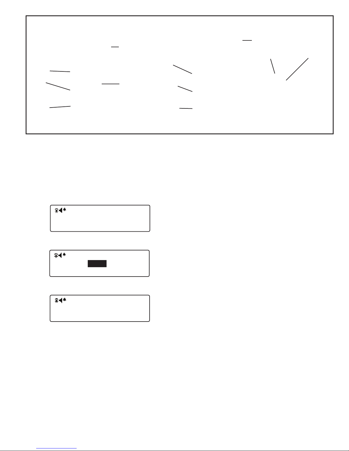
Swivel Clip
Power
Menu
Button
UP 1
Message
Button
Antenna
LCD
Display
Power
Select
Button
Down 1
Message
Button
Operation
Status LED
Alarm
Button
UP 16
Messages
Button
Front View
INTRODUCTION
The SuperCellTM SC500 is a small transceiver that provides Emergency Signaling, Alarm Monitoring, Call Back
and Messaging capability. Emergency Signaling may be
activated by pressing the Alarm Button or through lack of
motion if desired. SuperCellTM SC500 also has the ability
to monitor Emergency Alarm Signals from other Grace
Telemetry products.
Countdown Screen
Pre-Alert Screen
Motion Sensing Disabled Screen
General Operating Information
Power ON/OFF
The SuperCellTM is turned ON by simultaneously pressing and releasing both side buttons marked PWR. This is
accompanied by a series of up sweeping audio tones. A
start-up screen will appear that displays a Grace Indus-
tries logo, under which is displayed the model. (Model
details may be viewed from a Setup sub-menu also).
After the logo is briefly displayed the Status Screen appears. The top line summarizes the active features, and
status of such items as low battery warnings for example,
Down 16
Messages
Button
Back View
Top View
through a series of icons, that will be explained further in
this document.
The center of the screen shows a large number which is
countdown seconds until the alarm sounds due to lack of
motion. Moving the SuperCellTM resets the countdown. The
countdown will be shown in reverse during the Pre-Alert
If motion sensing is disabled this is indicated on the screen,
and no countdown is shown.
The right side of the screen displays OEM code and the I.D.
number. The top line shows the OEM Code, usually 9090,
described in detail later in this document. On the lower line
first two digits represent the System I.D. and the last two or
three digits represent the SC500 unit I.D. The bottom left
line of the screen shows the radio frequency, the radio firmware revision, and the type of firmware.
The SuperCellTM is turned OFF by simultaneously pressing
both PWR buttons and holding for about three seconds or
until the display shows the message Off. This is accompa-
If an alarm has been received then it is not possible to turn
the SuperCell
TM
This is to prevent unintentionally turning the SuperCellTM off
while clearing alarms. A message will be displayed on the
bottom status line indicating that the unit cannot be turned
off until the alarm has been cleared. To force the SuperCellTM to turn off, even with an active alarm, hold down the
Up button, along with the two PWR buttons. This could
be necessary in the case where alarms are coming in from
unknown or uncontrolled sources.
The SuperCellTM operation is controlled by six side push buttons noted in the photo above. The button on the left of the
SuperCellTM unit is the Mode or Menu button, the button on
the right is the Select button.
Note: The display Backlight is activated for ten seconds with
each button press or received Alarm message. The Backlight may be disabled in the unit Setup Menu, for covert
security operations.
.sdnuos mrala noitom fo kcal eht erofeb yletaidemmi ,esahp
.senot oidua gnipeews nwod neht dna pu seires a yb dein
.teser ro deraelc neeb sah mrala eht litnu ffo
1
Page 2
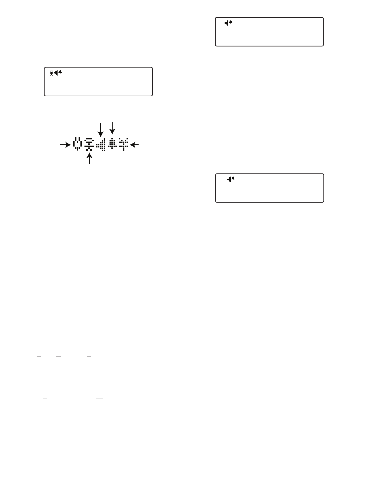
Display Screens and Functions
Sound Icon
Alarm Icon
Signal
Icon
Motion Icon
Low
Battery
Icon
AM16
915 MHzV2.9 Fire
Time To
Alarm:
OEM-9090
ID:DA-007
13
AM16
Send Message:0
Message 00
-120
Group: 0 User: 120 Sel to Send
AM16
Alarms Received
None
Alarm History
After initial startup, all conditions are reset by pressing both
PWR buttons simultaneously resulting in the SC500 Status
Screen being displayed. Pressing the Menu button brings
up the following screens in order:
Status Screen
Icons
The top line displays current unit configuration status, including (left to right) Signal Loss activation, Battery State when
low, Motion Sensing activation, Audio On/Off, and Inhibit
Timer activation. The time until alarm will be displayed to the
right of the top status line, when on any other screen than
the status screen. In the middle of right side of the screen
the unit I.D. number and OEM code is shown.
OEM codes are used as an additional method for isolating
systems having a large number of units operating in the
same geographic area. OEM codes are assigned by Grace
Industries to customers having this potential.
Alarm Monitoring Configurations
The SuperCellsTM can be programmed at the factory with
alarm monitoring disabled, preventing it from receiving
Alarms from other SuperCells . With alarm monitoring
TM
disabled, the SuperCellsTM can only send an Alarm and/or
receive a Call - Page signal. The top status line indicates
how the Alarm Monitor is configured. The different alarm
monitoring modes can only be programmed at the factory.
AM0 - Alarm Monitoring 0, alarm Monitoring disabled, will
not receive Alarms from other telemetry devices
AM1 - Alarm Monitoring 1 secived yrtemelet lla rof delbane ,
within same System I.D. group.
AM16 - Alarm Monitoring 16, enabled for all telemetry
devices within all 16 groups sharing same first digit of
System I.D.
Individual Group Blocks
Individual group blocks may be enabled or disabled over the
IrDA infrared link. When shipped from the factory all groups
are enabled. Enabling only a single group prevents receiving messages from other groups that may be on scene in a
mutual aid situation.
2
Send Message Screen
The Send Message option may be used to send one of 80
pre-programmed text messages. The pre-programmed text
messages are programmed to the SC500 through the SuperCellTM Database Manager Utility Program provided with
SuperCellsTM. The messages are accessed by going to the
Send Message screen, then using the Up/Dwn/*/# buttons
to chose the desired message. Up and Down change the
message count by one, while * and # change the count by
16. Once a message is selected, press and hold the Select
button for approximately three seconds, the message will be
transmitted and a Message Sent acknowledgment will be
displayed on the screen. Use Up/Dwn/*/# buttons to choose
other messages or the Menu button to leave the Send Message feature.
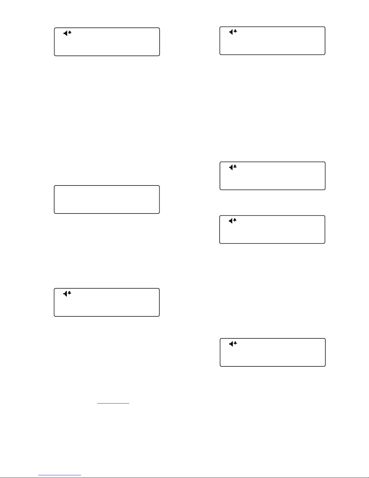
Alarm History Screen
Display Before Any Alarms Have Been Received
TM
When an Alarm is received from other SuperCell
, TPASS®
or other Grace Telemetry equipment, the I.D. of the unit in
alarm is shown on the display. If multiple units are in Alarm,
the I.D.s of the last thirty-two units in ala
rm will be placed
in the Alarm History Menu. The Operation Status LED rapidly strobes, alternating Red and Green. When the side
PWR buttons are pressed simultaneously; the SuperCellTM
is reset and will not respond to the same alarm for thirty
seconds. This is referred to as alarm-inhibit-time and tem-
porarily prevents the device from continually displaying the
same repeating alarm, which would impede the user from
operating the SuperCellTM menu system.
Warning: During this thirty second alarm-inhibit-time,
alarm signals from the same alarm will not be indicated or
displayed.
On the display status screen a solid alarm icon represents
that the unit is actively monitoring alarms. An outline alarm
icon indicates that the recently activated alarms are not being monitored. The Inhibit Timer may be enabled or disabled
in the Setup section described later. From the factory the Inhibit Timer is enabled, as disabling it causes multiple alarms
from the same unit to be received in successions requiring
multiple manual acknowledgments, which would impede the
user from operating the SuperCellTM menu system. Each
individual alarm must be acknowledged by pressing both
side PWR buttons. The bottom line of the display will show
how many alarms have been received that will need acknowledged. If more than eight alarms are received simultaneously, without any operator acknowledgment via the PWR
buttons, additional incoming alarms will not be processed;
until the operator acknowledges at least one alarm and the
thirty second Inhibit Timer expires for that alarm.
Page 3
CALL / PAGE Event Counters
Cpt. J. Doe
Run Time: 01:12:59
AM16
System Test
Hold SELect 3Sec
AM16
Setup Mode
Alarms Disabled
AM16
Hold SELect 35sec
for Setup Mode
AM16
SC500
v0.2.0-1995-02
Feb 2 201007:57:33
AM16
IRDA Transfer
Hold SELect 3Sec
AM16
PAGE: PAR: RECALL:
0 0 0
Event Counters
SETUP MODE
CALL / PAGE Screen
The Operation Status LED will rapidly strobe Green and
the SuperCellTM will vibrate and display Call/Page when a
Call-Page (evacuate) signal is received from In-Command,
Grace-Watch, LCD T3 Command Base, MX900 or MX2400.
Audio tones will also sound if audio is enabled. Receipt of
the Call/Page signal is acknowledged and reset by the user
simultaneously pressing both PWR side buttons.
The top line displays the number of times this unit has been
paged by the supervisory or commanding officer due to
developing hazard, and the number of Roll Call and PAR
messages received. The bottom line contains the count of
Call-Page/PAR/Roll Call messages received since the SuperCellTM was turned on. These values return to zero when
the SuperCell
TM
is turned off.
Name/On Time-Information Screen
Each SuperCell
TM
may be given a specific name or identity
via the IrDA infrared link, see the subsequent section on
programming unit for details. The contents of this identity
field are free format to use as desired. Examples: Station
One, Cpt. J. Doe, Shift 1A. The second line is an Hour meter shown the days/hours/minutes the SuperCellTM has been
running since being turned on.
Setup Mode Screen
SC500 settings that are rarely changed are under the Setup
Menu. Press SELECT to enter the Setup Mode and press
the Menu button to cycle through the ten SC500 setup
screens. To exit the Setup Mode reset the unit by simultaneously pressing and releasing both PWR side buttons.
The Operation LED will be solid Red while in Setup mode.
Approximately two minutes after the last button press, while
in Setup mode, the SuperCell
TM
, will revert to normal operating mode, and an up sweeping Power Up sound signature
will be generated.
IMPORTANT - Alarms Will Not Be Monitored While
In Setup Mode.
Setup Mode Screen 1
SC500 Firmware Data
Setup Mode Screen 2
The top display line shows the model of the SuperCell
The middle line shows the firmware version, build number,
and status code.
TM
.
System Link Test Screen
When used in conjunction with other compatible Grace Lone
Worker products, a complete system test (end to end) may
be initiated by pressing and holding the Select button for
three seconds. After Select has been held for three seconds
a Link Query message is transmitted, and the SuperCell
display shows a round trip timer, used to measure the complete system path test time. The display will show when a
Link Status message is received, in conjunction with a power-up sound sequence. If no Link Status Acknowledgment
message is received after five minutes, this will be indicated
via a simple audio beep and a message.
For more information on System Link Test see Mobile Lone
Worker Applications later in User’s Guide.
The bottom line of the display is the date this firmware version was created.
Pressing Select shows the firmware revision and features of
the radio transceiver, used to do Smart SignalingTM.
IrDA Transfer
TM
Setup Mode Screen 3
The SC500 can hold up to 64,770 Names (254 groups of
255) of 16 characters and 16 Messages, plus the Unit Identity. This Name and Message information is transferred to
and from a host computer via an infrared link and host PC
software. Several features of the SC500 may be configured/
enabled/disabled from the host PC.
To prevent accidentally entering the IrDA Transfer mode,
the Select button must be held continually for three seconds. Once in the IrDA Transfer mode unit will only respond
to commands from the host computer.
IrDA Transfer Continued on Next Page
3
Page 4

The Signal Lost Timer feature is to prevent users from unknowingly wondering out of range of the base/mobile system.
The Signal Lost Timer option may only be used in conjunction with other compatible Grace Lone Worker
products, turning it ON without these products in range
results in a Signal Lost alert message frequently appearing. Simply disable this alert to prevent these messages.
The SC500 is shipped with the Signal Lost Timer option
disabled or turned OFF unless stipulated otherwise by the
customer. The end user may enable this feature by selecting from one to fifteen minutes, in one minute increments,
to activate an alert on the SC500 when no signal has been
received from the Base, Watchdog, or MX products, for the
pre-selected time frame.
Setup Mode Screen 6
Current Countdown Screen
Current Time Setting Screen
Signal Lost Timer - Enabled or ON
Signal Lost Timer - Enabled or OFF
The display shows the current countdown first, followed by
the current time setting, in minutes. For example if three minutes is selected, and one whole minute has already passed,
the display will show 1/3, to indicate that there is one full minute remaining. The last minute is counted down in seconds.
The top status line shows the countdown progression.
Signal Lost
Signal Lost Display Screen
Signal Lost Count Down Time Screen
The first time a Signal Loss happens, until a signal is (re)
acquired, Signal Lost is displayed on the screen, the Super-
Signal Lost Continued on Next Page
IrDA Transfer Continued
AM16
Motion Sensing
Disabled
UP=+15, Down=-15 Secs.
AM16
Motion Sensing
45 Seconds
UP=+15, Down=-15 Secs.
AM16
Signal Lost Timer
Disabled
UP=+1, Down=-1
02
AM16
Signal Lost Timer
02/03 Minutes
UP=+1, Down=-1 Mins.
17
AM16
Signal Lost Timer
18 Seconds
UP=+1, Down=-1 Mins.
02
AM16
915 MHzV2.9 Fire
Motion Sensing
Disabled
OEM-9090
ID:DA-006
AM16
View Adjust
UP=+1,Down=-1,*=+10,#=-10
00
AM16
Out of Range
Signal Lost
Note: Alarms Will Not Be Monitored, and Alarms Can Not
Be Sent when in the the IrDA Transfer mode.
Press both PWR side buttons simultaneously to exit the IrDA
Transfer mode. Interrupting an IrDA Transfer in progress
may corrupt the internal SuperCellTM name data base. If that
occurs the internal SuperCellTM name data base may need
to be reloaded.
To program the Unit Identity enter the desired text into slot
zero of the Messages section of the host program.
View Adjust-Adjust-Adjust Screen Contrast
Setup Mode Screen 4
The screen shows a series of bars representing the display
contrast/viewing angle. Pressing the Up/Dwn buttons advances the bars by one, while */# advance the bars by ten,
until they wrap back to zero. The viewing setting may need
to be adjusted if the unit is exposed to wide temperature
variations.
Motion Sensing - Disable or Select Time to Alarm
Setup Mode Screen 5-A
Motion Sensing Option Disabled
Setup Mode Screen 5-B
Pre-Alert Motion Sensing Time Setting
SC500 is shipped with the Motion Sensing option disabled unless stipulated otherwise by the customer. The end
user may select, using the Up/Dwn buttons, from 30, 45,
60, 75, 90, 105 and 120 seconds to alarm after motion has
ceased. Approximately 12 seconds before the SC500 goes
into alarm a pre-alert is sounded. The pre-alert (a series of
up tones) is sounded at 11, 8, 5 and 2 seconds if no motion
is sensed. If no motion is sensed by the end of the pre-alert
the unit goes into Alarm.
When Motion Sensing is enabled the countdown timer represents the time to alarm. When motion is sensed the timer
will reset to the alarm time selected.
4
Page 5

Signal Lost Continued
AM16
Radio Range Test
Disabled
SELect to Toggle
AM16
SELect to Toggle
Backlight
Enabled
AM16
SELect to Toggle
AlarmButtonSound
Disabled
AM16
SELect to Toggle
Inhibit Timer
Enabled
AM16
SELect to Toggle
Sound
Enabled
CellTM vibrates for two seconds, and three alert tones are
sounded. Approximately every thirty seconds, the three alert
tones are sounded again, as a reminder, until a signal is (re)
acquired. To silence the Signal Lost Timer reminder audio,
reset the SuperCellTM by pressing both PWR side buttons
simultaneously. The Signal Lost count down time will then
be shown in reverse-video, to indicate that the SuperCellTM
is still out of range. When the appropriate signal is (re)acquired the count down time is reset, and the screens returns
to normal video.
Range Test Mode
Backlight
Setup Mode Screen 10
Pressing the Select button will toggle the Backlight state between Enabled/Disabled. It may be desirable to disable the
back light in covert operations, or situations where light can
draw undo attention to the operator.
Inhibit Timer
Setup Mode Screen 7
This mode is used to test the transmission and reception
range with other Grace Telemetry products. Primarily used
for testing of non-emergency signals during system installation. Pressing the Select button will toggle the Range Test
on and off.
Sound
Setup Mode Screen 8
The sound or audio tones can be enabled or disabled by the
user, for cases where a more covert operation is desired.
Pressing the Select button will
toggle the sound state between Enabled/Disabled. When discreet signaling is needed
the audio sound may be disabled. Reset, Call-Page and
Alarm alerts are silent with audio tones disabled. A solid
sound icon on the display status screen indicates that sound
is enabled. An outlined sound icon indicates that sound is
disabled so that the unit may be used in settings where
sound could bring undo attention to the operator in stealth
or covert situations. Power on and off signature tones are
emitted at all times, regardless of the sound on/off setting.
This setting overrides the setting of the Panic Alarm Button
Sound setting described next.
Emergency Alarm Button Sound
Setup Mode Screen 11
Use the Select button to enable or disable the Inhibit Timer.
With the Inhibit Timer enabled, when the side PWR buttons
are pressed simultaneously after an Alarm; the SuperCell
TM
is reset and will not respond to the same alarm for thirty seconds. See the previous Alarm Received section for details.
End Of Setup Mode Screens
Programming SuperCell
TM
The SuperCellTM may have its operating firmware updated
from a host computer via an infrared link. When the SuperCellTM is in range of host computer running SuperCellTM
name base management software, in upgrade mode, pressing both PWR side buttons simultaneously will initiate the
SuperCellTM firmware upgrade process. The completed process is indicated by power up tones.
SuperCellTM I.D.’s are programmed at the Factory and do not
require reprogramming unless desired by the end user. Normally a LCD T3, SM2000TM Command Base or Watchdog is
required to change a SuperCellTM’s I.D.
Setup Mode Screen 9
This setting determines whether pressing of the Alarm button generates an Alarm sound on the unit. If Sound is disabled, as described in the previous section, the Alarm button
will not make any local sound, even if this setting is enabled.
As supplied from the factory pressing the Alarm button does
N
OT generate an Alarm sound.
Refer to LCD T3 or SM2000TM Command Base Manual (Programming TPASS®3, PA2000TM and SuperCellTM) for detailed
programming information.
Programming SuperCellsTM I.D. is identical to programming
of TPASS®3 and PA2000TM units.
Do not try to up update the SuperCellTM firmware, or program
the SuperCellTM I.D. when the SuperCellTM batteries are low;
doing so may render the SuperCellTM inoperable.
5
Page 6

Low Battery Indication
AM16
System Test
Hold Select 3Sec
System Test Sent
Successful
System Test
Timed Out
System Test Sent
Trip Time: 0027
When approximately six hours of operating time remain in
standby mode, the SuperCellTM will display a plug icon on
the display status screen. The power-on tones are not emitted when SuperCellTM has a low battery. Low battery is also
indicated by the Operational Status LED changing to a periodic Red strobe. A double chirp sounds once every five minutes with audio enabled. Warning: There are no audible
low battery sounds with audio tones disabled.
When low battery is indicated, the battery should be recharged as approximately three hours of operating time
remain. The Rechargeable lithium battery is not user
replaceable.
With the charger provided, recharge time is approximately
six hours, from a low battery warning, and nine hours for
a dead battery. Due to current limits imposed by Intrinsic
Safety requirements, a unit that has gone completely dead
will have to be removed from the charging base and reinserted when the charging light turns red. Typical operation
time between recharging is approximately eighty hours in
standby/ready mode.
SuperCell
TM
Charging
which the SC500-OR is to be used, must have its Ping feature turned ON. The two devices operate as a system whereby the MX900 unit (with its PING feature turned on) will echo
back a normal on-mode polling signal that is received from a
Grace Industries SC500-OR two-way signaling device. The
SC500-OR device will receive the echo of its own on-mode
polling signal (sent from the MX900) and resets the Out-ofRange Notification timer. If the echoed signal sent from the
MX900 is not received, or conversely the MX900 does not
receive a polling signal from the SC500-OR within approximately 3 minutes, an audible warning sound will activate on
the SC500-OR indicating the effective range of the system
has been exceeded. This audible Out-of-Range notification
(a bell-like, double-chirping sound) will occur approximately
every 30-40 seconds until the signal link between the SC500OR and MX900 is re-established.
System Link Test
System Test Screen
When used in conjunction with other compatible Grace Lone
Worker products, a complete system test may be initiated
by pressing and holding the Select button for three seconds.
After Select has been held for three seconds a Link Query
message is transmitted, and the SuperCell
a round trip timer, used to measure the complete system
path test time:
TM
display shows
Charging
Adapter
Base
Plug Charger into outlet. It takes about twenty seconds for
the Green charger LED to come on. If it does not come on,
or a Red LED comes on, it indicates the battery is to hot or
cold, or has some other fault.
Charging is completed when the green charge LED starts to
slowly flash.
Mobile Lone Worker Applications
SC500-OR with Out of Range Notification
The SC500-OR is similar to the standard SC500 in most
respects but with the added feature of notifying the user
when they have exceeded the effective signaling range of a
compatible MX900 transceiver. The MX900 transceiver, with
12VAC Charger
6
System Test Sent Screen
The display will show the following when a Link Status message is received, in conjunction with a power-up sound
sequence:
System Test Successful Screen
If no Link Status Acknowledgment message is received after
five minutes, this will be indicated via a simple audio beep
and a message similar to the one below:
System Test Timed Out Screen
Note: The complete system path may contain items beyond
the control of Grace Industries, such as satellite delays. System Test times could vary considerably.
Page 7

Operation Status LED Indicators:
Periodic strobe of Green LED—Standby, ready mode Periodic strobe of Red LED—Low battery
indication, ready mode
Rapid strobe of Green LED—Call-back signal received Rapid strobe of Red LED—
Alarm activated by pressing top alarm button
Rapid strobe of alternating Green and Red LED—Alarm received from other SuperCellTM,
TPASS® or PA2000TM
Approximate Dimensions - 4” H (including antenna) x 2-3/16” W x 1-3/8” Deep
Weight – 5.6 oz. (approximate)
Battery-Rechargeable Lithium, providing over 80 hours of use
High Frequency 2 Way Radio - 902-928 MHz (No FCC License Required)
Smart-Signal Technology - Each SuperCellTM is a Smart Repeater for critical signals providing superior
performance
Manual Alarm Activation - Push Top Button to send an alarm signal. A Red LED will strobe rapidly with
momentary vibration
Motion Sensing - end user may disable or select from 30, 45, 60, 75, 90, 105 and 120 seconds to alarm after
motion has ceased. A Red LED will strobe rapidly with momentary vibration
Receive Call-Page Signals the word Call Page appears on display Initiated from Command Base or Watchdog,
vibration and optional audible alert
Alarm-Receive – Display of ID number, LED alternating Red/Green Strobe, vibration and optional Audible Alert
Power-on Confirmation – Periodic Strobe of Green LED
Low Battery Indication – Low battery icon appears when approx. 4 hours of operating time remaining, Periodic
Strobe of Red LED and optional Audible Alert
Optional audible tones – for alarm, alarm-received, call-back and reset
Check-in Status Signal Periodically transmitted to LCD T3, SM2000 Command Bases, Watchdog and many
other Grace Telemetry products
SuperCellTM SC500 SPECIFICATIONS AND FEATURES
When a train is detected, the Train Detector sends an Evacuation Alarm signal to the SC500. The SC500 displays the
EVACUATION message and sounds the evacuation tones.
The supervisor can immediately warn other personnel on
site of approaching rail traffic. SC500 also repeats the Train
Detector the Evacuation Alarm signal.
Both side buttons must be pressed simultaneously to clear
the Evacuation alarm and silence the audio alarm on the
SC500 for one minute. If the Train Detector is not reset the
audio Alarm on the SC500 will automatically re-activate after
1 minute.
To reset the Track-Watch Train Detector and the Track-side
Warning Alarm with the SC500, the STAR “*” key must
pressed and held for 3 seconds. After the reset message is
sent three acknowledgement tones will sound (beep, beep
and beep). The Track-Watch Train Detector will reset and be
fully operational within 15 seconds.
All signals from the Track-Watch Train Detector and other
telemetry devices are “Smart-Signal” repeated by, SC500s,
TPASS-3-TW, Micro TPASS Repeaters and the Track-Side
Warning Alarm.
To turn SC500 “OFF”, press both side buttons simultaneously. Please note that SC500 MUST be in the ON mode to
receive and repeat emergency signals.
Always test SC500 for proper operation prior to use.
Remote Reset with SuperCell SC500
SuperCELLTM SC500 Track-Watch System Application
7
Page 8

305 Bend Hill Road, Fredonia,
PA16124 U.S.A. 724-962-9231
www.graceidustries. com
© Grace Industries, Inc. Printed in U.S.A. SuperCell-500 06 2011 UI
 Loading...