

Page 1
Copyright Nov 15, 2017
Jim M. Bagley, GraceWood, Inc
(Reproduction Prohibited)
Version 3.7
Page 2

Table Of Contents
IMPORTANT SAFETY INSTRUCTIONS..................................................................................................... 4
Specications And Overview.................................................................................................................. 5
Specications And Overview.................................................................................................................. 6
Included Parts And Tools....................................................................................................................... 7
Wheel Alignment.................................................................................................................................. 8
Installing The Encoder Onto The Carriage.............................................................................................. 9
Installing Encoder Onto The Quilting Machine....................................................................................... 10
Placing The Quilting Machine Onto The Carriage And Connecting Encoders............................................. 11
Attaching Thread Mast........................................................................................................................ 12
Threading The Quilting Machine...........................................................................................................13
Winding The Bobbin........................................................................................................................... 14
Installing The Bobbin Case.................................................................................................................. 15
Adjusting Thread Tension.................................................................................................................... 16
Plugging In The Cables....................................................................................................................... 17
Final Checklist.................................................................................................................................... 18
Basic Controls.................................................................................................................................... 19
Main Menu......................................................................................................................................... 20
Sewing Modes.................................................................................................................................... 21
Sewing Modes Continued.................................................................................................................... 22
T ools Menu........................................................................................................................................ 23
Tools Menu Continued......................................................................................................................... 24
Tools Menu Continued......................................................................................................................... 25
Repair Kit........................................................................................................................................... 26
The Needle Plate................................................................................................................................ 27
The Hook Holder................................................................................................................................. 28
Hopping Foot..................................................................................................................................... 29
Timing The Machine........................................................................................................................... 30
Thread Tension.................................................................................................................................. 31
Changing A Needle............................................................................................................................. 32
Cleaning Bobbin Area.......................................................................................................................... 33
Oiling the Machine: Head.................................................................................................................... 34
Oiling the Machine: Hook.................................................................................................................... 35
14+ Troubleshooting Instruction.......................................................................................................... 36
Needle Information............................................................................................................................. 38
Thread Information............................................................................................................................ 39
Additional Tips................................................................................................................................... 40
2
Page 3

IMPORTANT SAFETY INSTRUCTIONS
When using an electrical machine, basic safety precautions should always be followed, including the
following:
Read all instructions before using (this machine).
DANGER - To reduce the risk of electric shock:
1. The machine should never be left unattended when plugged in. Always unplug this machine from
the electric outlet immediately after using and before cleaning.
WARNING - To reduce the risk of burns, re, electric shock, or injury to persons:
1. Do not allow this machine to be used as a toy. Close attention is necessary when this machine is
used by or near children.
2. Use this machine only for its intended use as described in this manual. Use only attachments
recommended by the manufacturer as contained in this manual.
3. Never operate this machine if it has a damaged cord or plug, if it is not working properly, if it has
been dropped or damaged, or dropped into water. Return the machine to the nearest authorized dealer
or service center for examination, repair, electrical or mechanical adjustment.
4. Never operate the machine with any air openings blocked. Keep ventilation openings of the sewing
machine free from the accumulation of lint, dust, and loose cloth.
5. Never drop or insert any object into any opening.
6. Do not use outdoors.
7. Do not operate where aerosol (spray) products are being used or where oxygen is being administered.
8. To disconnect, turn all controls to the off position, then remove the plug from the outlet.
9. Do not unplug by pulling on cord. To unplug, grasp the plug, not the cord.
ii) Keep ngers away from all moving parts. Special care is required around the sewing machine
needle.
iii) Always use the proper needle plate. The wrong plate can cause the needle to break.
iv) Do not use bent needles.
v) Do not pull or push fabric while stitching. It may deect the needle causing it to break.
vi) Switch the sewing machine off when making any adjustments in the needle area, such as
threading needle, changing needle, threading bobbin, or changing presser foot, etc.
vii) Always unplug sewing machine from the electrical outlet when removing covers, lubricating,
or when making any other user servicing adjustments mentioned in the instruction manual.
Connect this machine to a properly grounded outlet only. See Grounding Instructions.
SAVE THESE INSTRUCTIONS
Do not discard box or packaging
3
Page 4
IMPORTANT SAFETY INSTRUCTIONS
GROUNDING INSTRUCTIONS
This product must be grounded. In the event of malfunction or breakdown, grounding provides a path
of least resistance for electric current to reduce the risk of electric shock. This product is equipped with
a cord having an equipment-grounding conductor and a grounding plug. Plug the cord from the quilting
machine into a surge protector. The surge protector must be plugged into an appropriate outlet that is
properly installed and grounded in accordance with all local codes and ordinances.
DANGER - Improper connection of the equipment-grounding conductor can result in a risk of electric
shock. The conductor with insulation having an outer surface that is green with or without yellow
stripes is the equipment-grounding conductor. If repair or replacement of the cord or plug is necessary,
do not connect the equipment-grounding conductor to a live terminal. Check with a qualied electrician
or serviceman if the grounding instructions are not completely understood, or if in doubt as to whether
the product is properly grounded.
Do not modify the plug provided with the product - if it will not t the outlet, have a proper outlet
installed by a qualied electrician.″
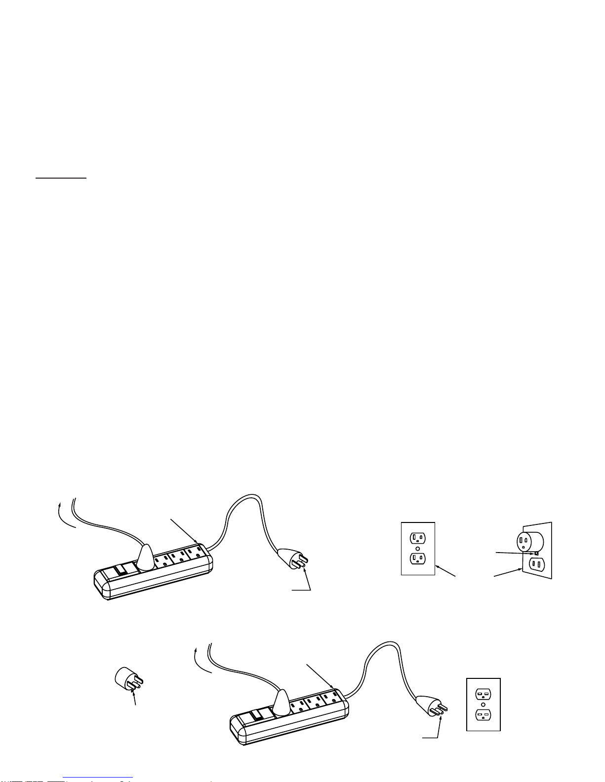
This product is for use on a nominal 120 V circuit, and has a grounding plug that looks like the plug
illustrated in sketch A in Figure 61.1. A temporary adaptor, which looks like the adaptor illustrated in
sketches B and C, may be used to connect this plug to a 2-pole receptacle as
shown in sketch B if a properly grounded outlet is not available. The temporary adaptor should be used
only until a properly grounded outlet can be installed by a qualied electrician. The green colored rigid
ear, lug, and the like, extending from the adaptor must be connected to a permanent ground such as
a properly grounded outlet box cover. Whenever the adaptor is used, it must be held in place by the
metal screw.
A qualied electrician should be consulted if there is any doubt as to whether an outlet box is properly
grounded.
Grounding Methods
Figure 61.1
Surge
Protector
To Sewing
Machine
Adapter
Grounding
Pin
(A)
Surge
Protector
To Sewing
Machine
Metal
Screw
Cover of
Grounded
Outlet Box
(B)
Grounding
Means
(C)
Grounding
PIN
(D)
4
Page 5
Specications And Overview
1. Height: 480 mm, 19”
2. Width: 395 mm, 15.5”
3. Length: 585 mm, 23”
4. Weight: 42 Lbs
5. Quilting Arm Length: 15” W 8.5” H
6. Maximum SPM: 1800
7. Minimum SPM: 90
8. Input Voltage: 110-220 VAC
9. Peak Power Consumption: 300 W
10. Timing Belt System
11. Bobbin Type: Large M Class
12. OLED Screen
13. Custom Ergonomic Handles and Handlebars for
efciency and extended use
14. Built in Bobbin Winder
15. Dual Thread Tension Guides, for precise tension.
Front
Rear
Left
Right
5
Page 6
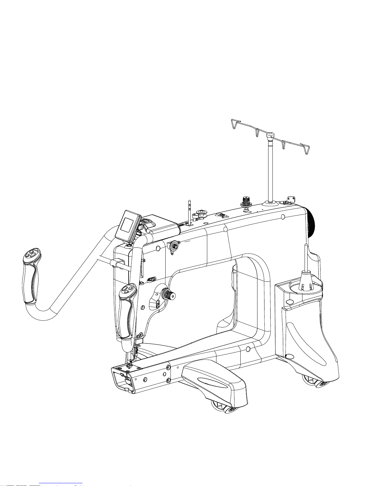
Specications and Overview
12
13
10
11
7
6
5
8
9
4
3
1
16
2
18
14
15
1. Thread Mast Base
2. Bobbin Thread Guide
3. Bobbin Thread Tensioner
4. Bobbin Thread Cutter
5. Bobbin Wind Stand
6. Bobbin Sensor
7. Dual Thread Tension Guide
8. Small Thread Tensioner
9. Large Thread Tensioner
10. Thread Guides
11. Take Up Lever
12. Lamp
13. Needle Bar
14. Needle
15. Hopping Foot
16. Thread Stand
17. Carriage Wheels
18. Handwheel
19. Bobbin Case
17
19
6
Page 7
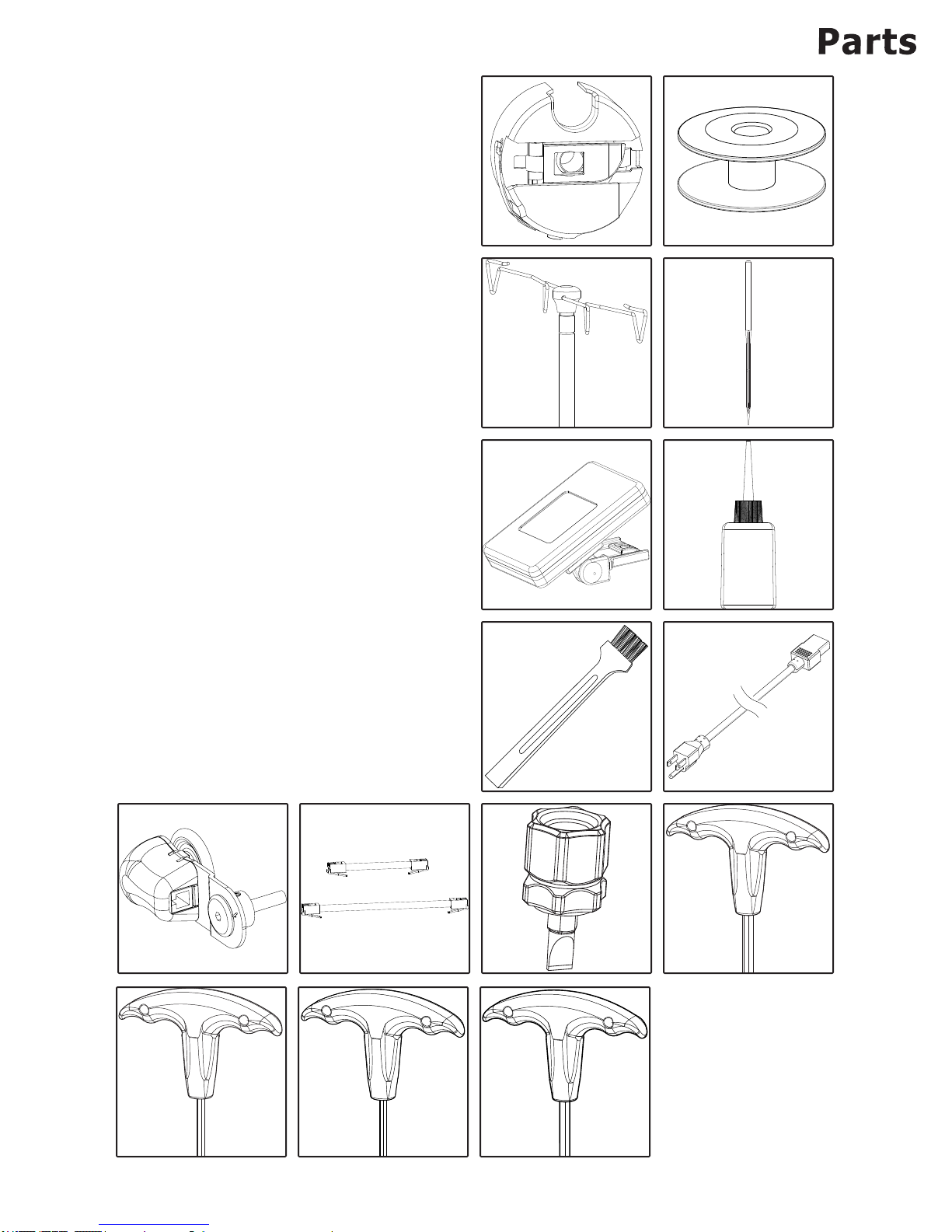
Included Parts And Tools
Please make sure all pieces were included in your kit.
1. Bobbin Case - 1
2. M Class Bobbin - 3
3. Thread Mast - 1
4. Needle - 10
5. OLED Screen with Cable - 1
6. Oil Bottle - 1
7. Lint Brush - 1
8. Power Cord - 1
9. Encoder - 2
• Silver Spring - 1
• Black Spring - 1
10. Top Encoder Cable - 1
(pre-installed in silver spring encoder)
11. Bottom Encoder Cable - 1
(pre-installed in black spring encoder)
Tools:
12. Flat Head Screw Driver - 1
13. 4 mm Allen Wrench - 1
14. 3 mm Allen Wrench - 1
15. 2.5 mm Allen Wrench- 1
16. 2 mm Allen Wrench -1
1
3
2
4
Repair Kit Parts
1. M3 Thumb Screw - 1
2. Encoder Spring Lower (Black) - 1
3. Encoder Spring Upper (Sliver) - 1
4. Encoder O-Ring - 2
5. Timing Spacer - 1
9
10
11
5
7
12
6
8
13
14
15
16
Page 8
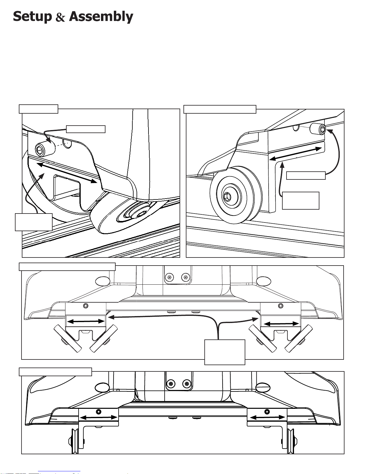
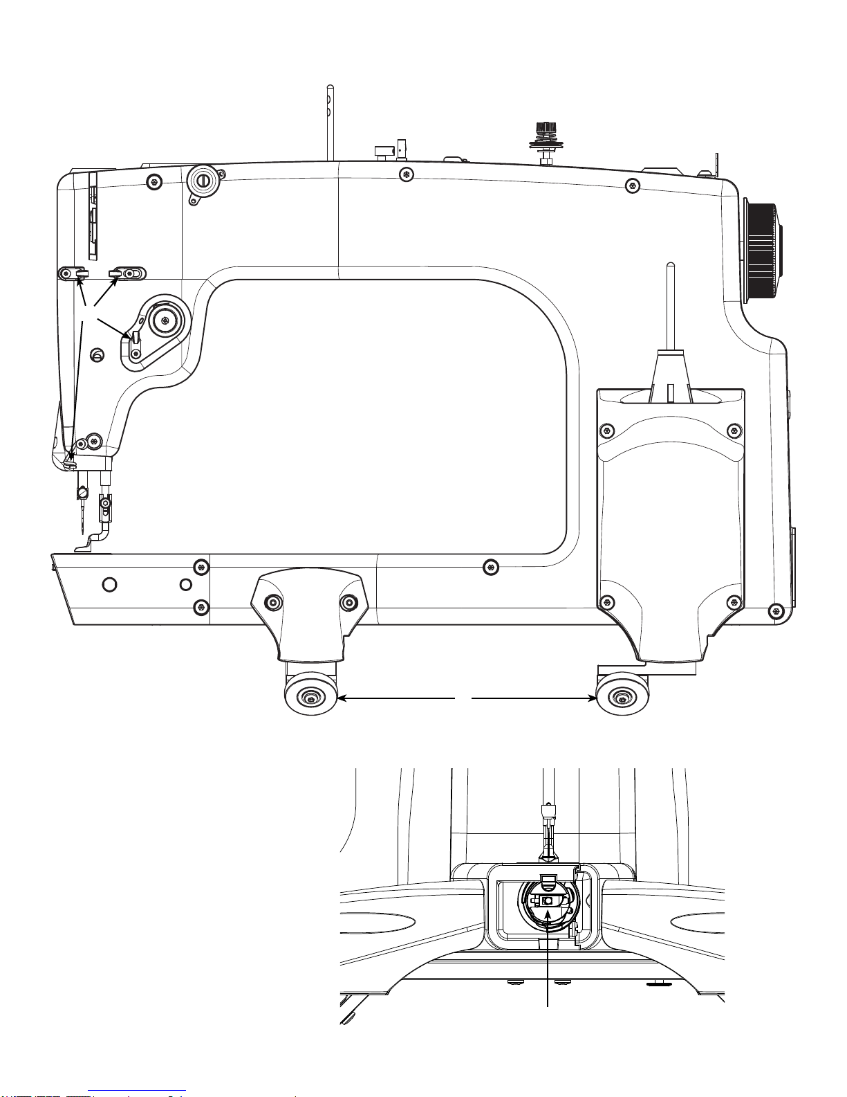
Wheel Alignment
1. Using the 3mm allen wrench, loosen the set screws located above each of the wheels on the
machine.
2. Estimate the distance the wheels need to be moved to sit on your carriage, and set the machine
onto the carriage on your quilting frame.
3. Readjust the wheels as necessary while centering the machine between the left and right wheels.
4. Tighten the set screws using the 3mm allen wrench.
Dual-Track
M6 Set Screw
Double Track
Bracket
Double-Single Track Adaptor
Single Vertical Track
M6 Set Screw
Single Track
Bracket
Single Vertical Track
Double-Single
Track Adaptor
Height Spacer
8
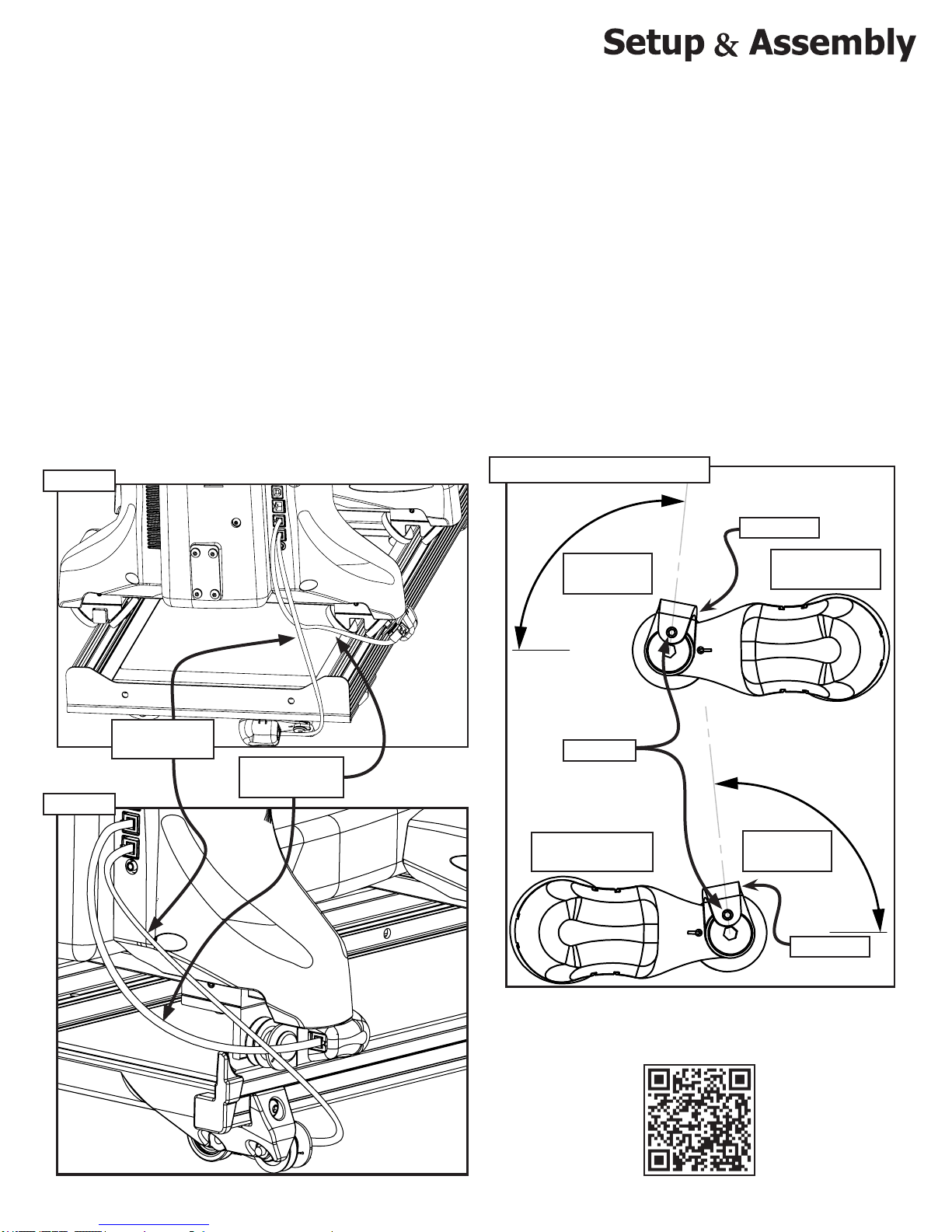
Page 9
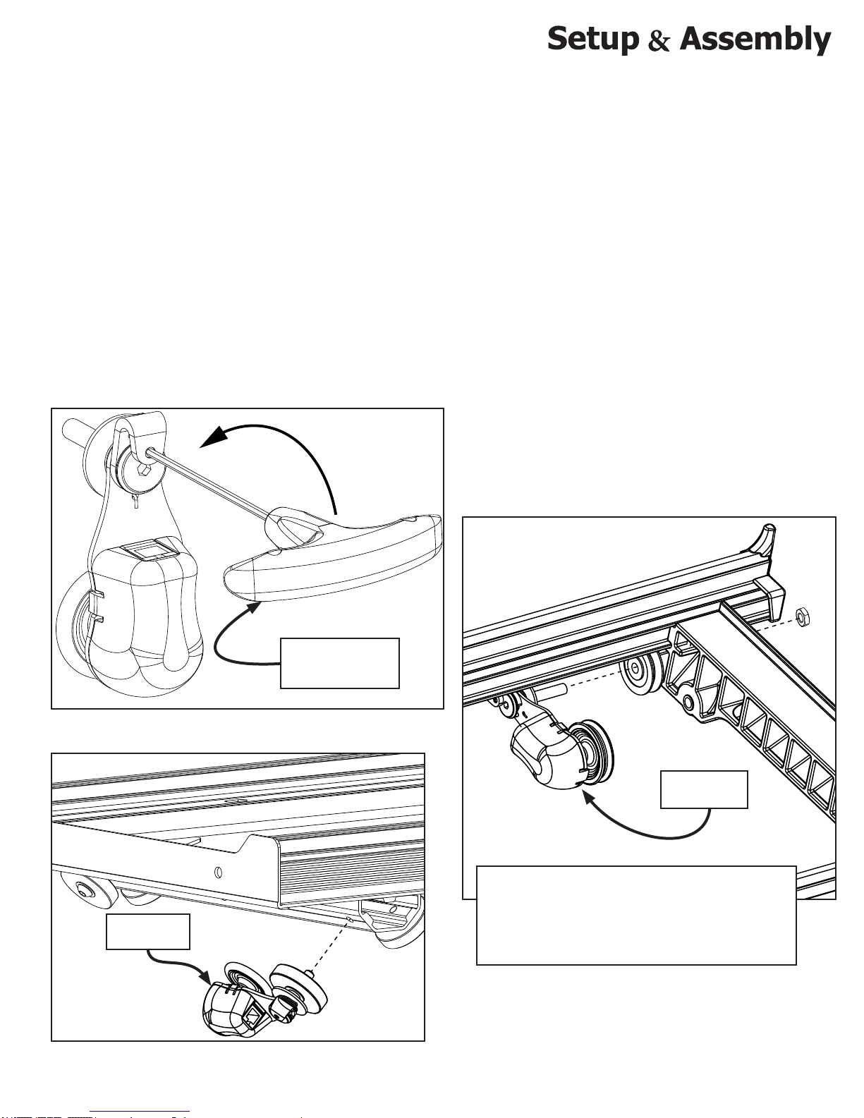
Installing The Encoder
Onto The Carriage
1. Use the 4mm allen wrench to remove the M6 x 16mm SBHCS from the outer, left, rear wheel, in the
Bottom Plate.
2. Put the wheel, which you just removed, onto the encoder wheel bolt of the black spring encoder, with
the anged hub facing out, away from the encoder.
3. Use the 2mm allen wrench to loosen the set screw in the lock collar, without removing it, so that the
encoder wheel bolt can turn freely.
4. Hold the encoder to prevent it from rotating, and use the 4mm allen wrench to fasten the encoder
wheel bolt into the hole made available in the rst step.
5. Keep the spare bolts with your quilting frame’s spare parts.
6. Leave the encoder’s set screw loose. They will be tightened after you place the sewing machine on
your frame.
Encoder With
Black Spring
Loosen The Set
Screw Using The
2mm Allen Wrench
Encoder With
Black Spring
If the encoder is attached on the inside of the
bottom carriage, as shown above, the encoder
spring must be tensioned in the opposite direction.
See the encoder spring tensioning image on page
11 for direction on tensioning the encoder spring
9
Page 10
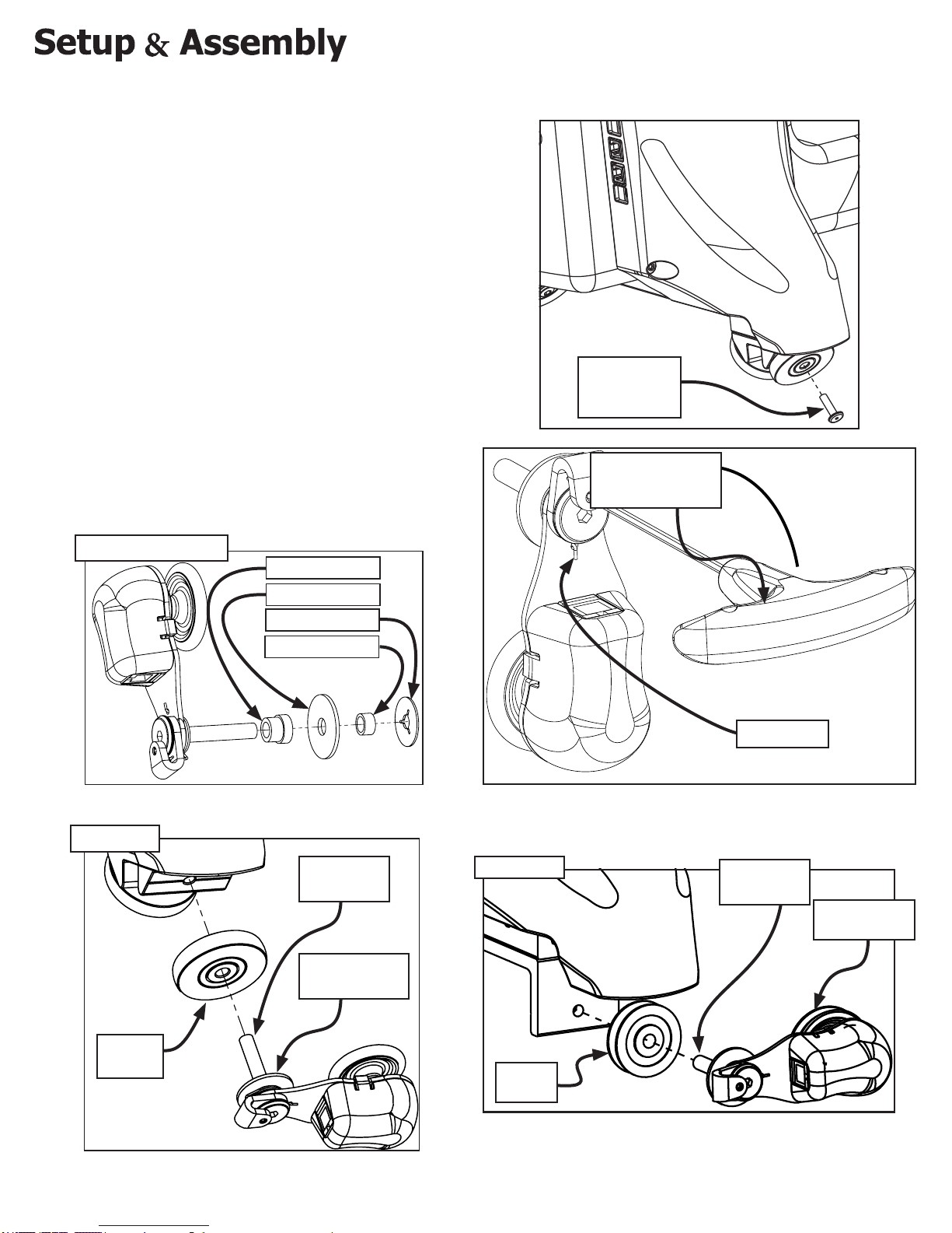
Installing Encoder Onto
1. Use the 4mm allen wrench to remove the
M6 x 16mm SBHCS from the outer, left,
rear wheel, in the sewing machine.
2. Put the wheel, which you just removed,
onto the sliver spring encoder wheel bolt
with the anged hub facing out, away from
the encoder.
3. Before attaching the encoder, use the 2mm
allen wrench to loosen the set screw in the
lock collar, so that the encoder wheel bolt
can turn freely.
4. Hold the encoder to prevent it from rotating,
and use the 4mm allen wrench to fasten
the encoder wheel bolt into the hole made
available in the rst step.
5. Leave the encoder’s set screw loose. They
will be tightened after you place the sewing
machine on your frame.
The Quilting Machine
Remove the
M6 x 16mm
SBHCS
Loosen The Set
Screw Using The
2mm Allen Wrench
Encoder Assembly
Option 1
Shoulder Spacer
Washer
Plastic Stop
Wheel Spacer
Encoder
Wheel Bolt
Encoder With
Silver Spring
Option 2
Sliver Spring
Encoder
Wheel Bolt
Encoder With
Silver Spring
Flat Track
Bearing
“V” T rack
Bearing
10
Page 11
Placing The Quilting
Machine Onto The Carriage
And Connecting Encoders
1. Place the bottom plate onto the quilting frame,
2. Place the sewing machine onto the bottom plate. Make sure that the encoder rides on the
carriage track.
3. Plug in the encoder cables from each of the encoders into the sewing machine. The longer
cable is used for the encoder attached to the carriage, while the shorter cable is used for the
encoder attached to the sewing machine.
4. Rotate the lock collar on the encoder up about 100 degrees or until you feel adequate push back
from the spring. While holding the lock collar in that position, tighten each set screw using the
2mm Allen Wrench.
Option 1
Option 2
Long Encoder
Cable
Short Encoder
Cable
Encoder Spring Tensioning
100 degrees
up
Set Screw
Bottom Encoder/
Black Spring
Lock Collar
Top Encoder/
Silver Spring
100 degrees
up
Lock Collar
An encoder assembly tutorial is availablie on our website at:
http://www.qniquequilter.com/videos/tutorials/
QR CODE
11
Page 12
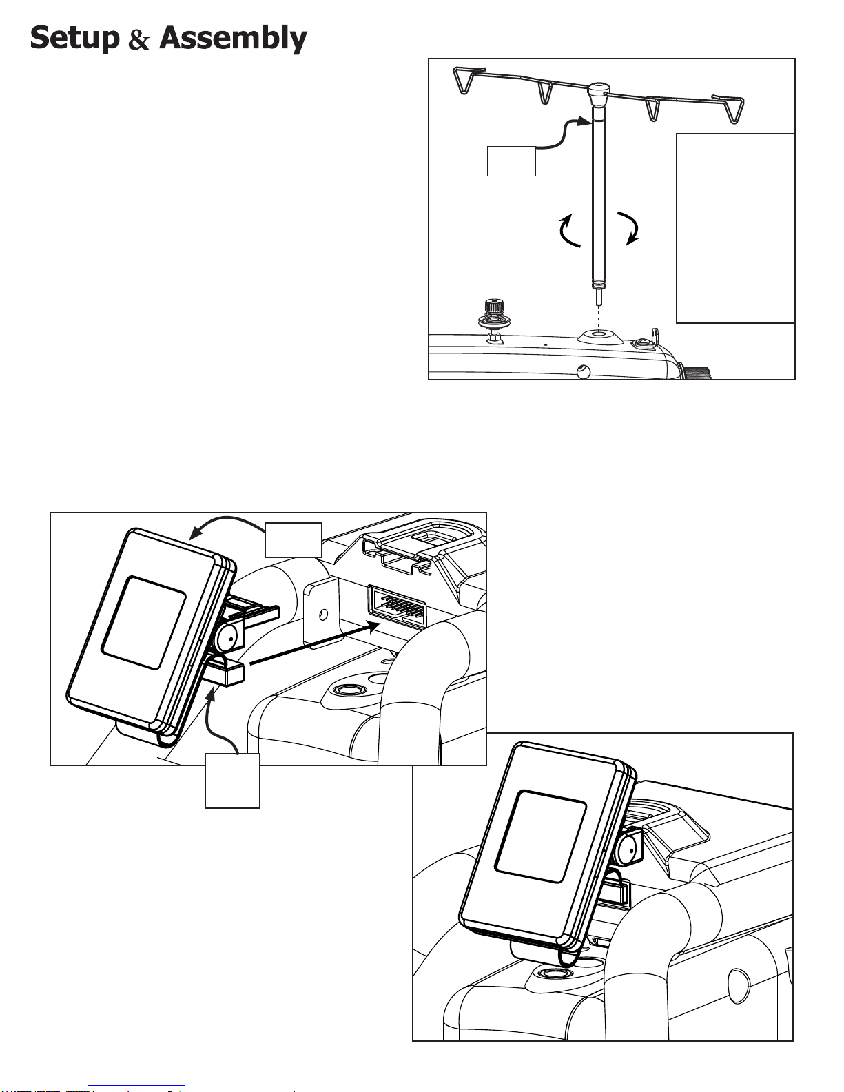
1. Attach the thread mast to the thread mast
base.
2. Make sure it is securely attached by screwing
it on.
3. The guide loops on the thread mast should
be positioned so that they are directly above
the thread stands.
Connecting Front Display
Attaching Thread Mast
Thread
Mast
The thread
mast acts as a
guide for the
thread, and
makes it less
likely to get
snagged or
looped around
any object.
• Connect the Display ribbon cable from the Display to the display
mount, and attach the display by snapping it into the Display hub.
Display
Screen
Display
Ribbon
Cable
12
Page 13
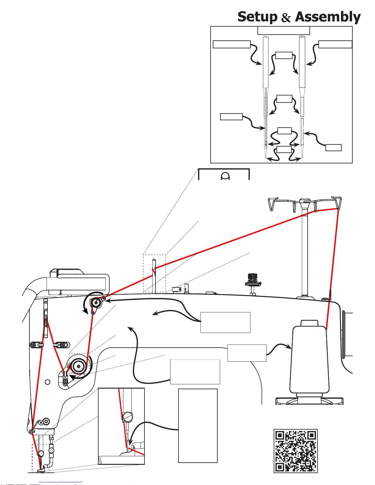
Threading The Quilting Machine
1. Place thread on the cone style thread stand.
2. Pull the thread through both loops of the thread
mast.
3. Put the thread through the top hole on the thread
guide, wrap the thread around and through the
bottom hole of thread guide at the middle of the
machine.
4. Take the thread through the rst thread tensioner,
between the two disks.
5. Loop the thread down around the second tensioner.
6. Pull the thread through the tensioner disks and
around the spring hook.
7. Feed the thread through the right thread guide up
to the take up lever.
8. Pull the thread through the hole in the take up
lever.
9. Feed thread into the left thread guide below.
10. Pull the thread down towards the needle
and through the bottom thread guide.
11. Feed the thread through the eyelet in
the front of the needle arm.
12. Feed the thread through the eye of
the needle.
Needle Diagram
Front View Side View
Shank
Shaft
Groove
Eye
Point
Scarf
2
8
4
9
7
5
6
11
10
11
12
12
3
Make sure the
thread is between
the tensioner discs
Use cone style
thread thread
The Thread Must
Go Through The
Check Spring
1
*Be sure to
install the
Needle with
the scarf
A threading tutorial is availablie on our website at:
http://www.qniquequilter.com/videos/tutorials/
toward
the throat
of your
QR CODE
machine.
13
Page 14

Winding The Bobbin
1. Place the thread on the thread stand.
2. Pass the thread through the hooks in the thread mast.
3. Pull the thread through the bobbin thread guide at the back of the
quilting machine.
4. Loop the thread around the spring hook and around the thread
tensioner.
5. Wrap the thread around the bobbin as shown.
6. Start the bobbin winder by pushing the bobbin winder cam into the
bobbin.
When the bobbin is full it will automatically stop.
Thread
Mast
The bobbin winds in a
clockwise direction
Adjust the
cam so that
the bobbin
does not
over-ll
5
6
2
Push Bobbin
Winder Cam
Thread
Cutter
When the bobbin is full you can cut
the thread with the thread cutter
found next to the bobbin stand.
A bobbin winder tutorial is availablie on our website at:
http://www.qniquequilter.com/videos/tutorials/
QR CODE
4
1
Make sure the
thread is between
the tensioner discs
3
The bobbin winder runs
on a separate motor from
the quilting machine. This
allows you to wind bobbins
with the quilting machine
running or stopped, as
long as the power is on.
14
Page 15

Installing The Bobbin Case
1. Remove the bobbin case.
2. Place the full bobbin into the bobbin case.
3. Pull thread from bobbin through the bobbin case.
4. Place the bobbin case into the quilting machine with the lever arm at the 3 o’clock position, and
press it into place until it “clicks” in.
Pull the
Lever To
Release The
Bobbin Case
Bobbin
Bobbin
Case
1
*Note the direction the
thread is coming off the
bobbin in relation to the
bobbin case.
2
Pull Several Inches
Of Thread Out Of
The Bobbin Case
Do Not Use The
Lever when
Inserting The
Bobbin Case.
Bobbin
Case
3
Hook
Assembly
4
15
Page 16

Adjusting Thread Tension
Note: The thread tension will need to be adjusted
anytime the thread is changed. Follow the process
below to adjust the thread tension for the thread you
have selected. See page 31 for more information about
properly tensioning your thread.
1. Set the bobbin case, with the bobbin inside, in your hand
on its side and pull up on the thread. The thread should
pull the bobbin case vertical and the thread should ow out
of the bobbin without lifting the bobbin off of your hand. If
the bobbin pulls out of your hand, the tension is too tight
and will need to be loosened. If the thread ows out of the
bobbin on its side but does not pull the bobbin vertical the
tension is too loose and will need to be tightened.
When the thread
is pulled The
bobbin will turn
clockwise.
2. To adjust the bobbin tension, locate the larger
of the two screws on the bobbin case. Tighten the
tension in minute adjustments by twisting the large
screw to the right or clockwise. To loosen, twist the
large screw to the left or counterclockwise minutely.
Turn the screw clockwise to
increase bobbin tension and
counter-clockwise to decrease
bobbin tension
3. Adjust the top thread tension after the bobbin tension is
established. Start with the knob loosend so that none of the screw
is showing, then slowly increase the tension until the thread tension
is balanced and the thread knots in the middle layers of your fabric.
A thread tension tutorial is availablie on our website at:
http://www.qniquequilter.com/videos/tutorials/
QR CODE
16
Page 17

Plugging In The Cables
Power
Adapter
Off
On
Quilt Motion
Tablet
(For optional Automation Accessory)
Once all the components are connected,
you can attach the power cord to the
sewing machine, then connect the
power cord to an outlet.
When you are ready to begin sewing, turn
on the machine using the power switch
located on the back of the machine.
Below is a reference of how the machine
should be congured.
» USB Connector Port
(Programming only)
» Quilt Motion Control
» Encoder
» Encoder
Power
Cord
Long
Encoder
cable
» Foot Pedal
(For sit down system)
Short
Encoder
Cable
17
Page 18

Before you begin sewing make sure that:
• The mast is attached and tightened securely
• The bobbin winder was able to ll a bobbin and stops when full
• The quilting machine is threaded correctly
• The handle bars are not loose
• The display hub is secured to the handle bars
• The display powers on and displays the quilting settings
• Check for bent needles
• The needle is secured rmly into the needle bar
• The power cord is securely connected
No objects other than quilting materials should
be near the needle or quilting area of the
quilting machine.
Final Checklist
18
Page 19

Basic Controls
1. Menu - This button returns the user to the main menu screen from any other screen.
2. Back - This button will return the user to the previously viewed screen.
3. Needle Up / Needle Down - A quick push and release of this button allows you to cycle the
needle to the up or the down position. Holding this button for three seconds will change the default
stop needle position. When the machine powers up the needle will always default to the up position.
4. Start / Stop , Select - This button will select the highlighted function icon. When in a sewing
function menu such as regulate, manual or baste this button will cause the sewing machine to sew,
or stop sewing.
5. Increase , Scroll up - When in a menu this button will scroll up for navigation of listed icon
selections. When a variable window is highlighted, such as speed, stitches / inch, time or cycles,
this button will allow the user to increment the value of the variable up.
6. Decrease , Scroll down - When in a menu this button will scroll down for navigation of listed icon
selections. When a variable window is highlighted, such as speed, stitches / inch, time or cycles this
button will allow the user to increment the value of the variable down.
Menu
Back
Menu Controls
Select
Scroll Up
1
3 4
2
5
6
Scroll
Down
1
2
Need Up/
Needle Down
Sewing Controls
Start/
Stop
3
Decrease
Speed
4
Increase
Speed
5
6
19
Page 20

Main Menu
The Main Menu provides access to the different sewing methods and access the tools menu.
Regulated Precise -
In both regulated modes, the sewing machine will adjust its rate of stitching based on the speed at
which the user moves the machine on the quilt frame, in order to maintain a constant stitch length.
The screen will show you the current state, and sewing settings. In Precise Mode, the machine will
stop sewing if it is not being moved.
Regulated Cruise -
In cruise mode, the machine will not stop sewing if it is not being moved. The Stitch speed will not
drop below 5%, even when the machine is at rest.
Manual Mode -
This mode allows you to set the speed of the machine. When sewing in this mode the machine
speed is xed. To get consistent stitch lengths you must adjust your movements to match the
speed of the machine. This mode is especially useful for small continuous stippling type patterns,
as opposed to regulated stitching functions.
Baste -
The baste feature allow the user to place a temporary stitch at large intervals to secure fabric
layers together.
Tools-
The tools menu allows access to information regarding the sewing machine. You can also enter the
diagnostics menu to test different aspects of the machine to identify issues.
20
Page 21

Sewing Modes
Over-speed Indicator -
This will be green when the sewing
machine is being moved within the
speed limit for sewing. When the
indicator turns red and beeps it means
the sewing machine is being moved
more quickly than the sewing machine
can stitch, and will be unable to maintain
the SPI setting. In addition to the red
indicator, an audible beep will sound
until the speed is reduced sufciently
to allow the machine to regulate.
Needle Position Indicator-
This is a visual representation for the
default needle position when sewing is
stopped. T o change, hold the left needle
up/down button for three seconds.
Stitches Per Inch
setting
Over-speed
Indicator
SPI Setting (Stitch Per Inch) -
Shows the current SPI setting, the
minimum is 4, and the maximum is 16.
Start / Stop Indicator -
This button indicates what action the
sewing machine will take when the
start/stop button is pressed.
Needle Stop
Position
Indicator
(up position)
Needle Stop
Position
Indicator
(down position)
Start \ Stop
Indicator
21
Page 22

Sewing Modes Continued
• The baste stitch can be set to
small, medium, or large.
MANUAL
Large
Stitch Size Setting
• The Speed indicator shows current
sewing speed as a percentage of
the maximum 1800 stitches per
minute. The minimum being 5%
and the maximum of 100%.
Speed Setting
Indicator
22
Page 23

Tools Menu
The tools menu allows access to
information regarding the sewing
machine. You can also enter the
diagnostics menu to test different
aspects of the machine to identify
issues.
Stitch / Time
This screen displays the number
of stitches sewn and hours the
machine has run. Hours and
stitches can be reset individually.
T o reset either one, navigate to the
option you wish to reset using the
+ or - keys and then press select.
Total -
This area cannot be reset. The
sewing machine will keep track of
the total number of stitches sewn,
and hours the machine has run.
HOURS
0 0:00
RESET
TOTAL
STITCH
0
RESET
TOTAL
HOURS
0
23
Page 24

Tools Menu Continued
SYSTEM
INFORMATION
MAIN REV:
V1.6.0
03/28/14
DISPLAY REV:
V1.2.2
03/28/14
System Information
This screen will display the motor
control rmware version and the
display control rmware version.
DIAGNOSTICS
ENCODER TEST
BUTTON TEST
SENSOR TEST
SELF TESTS
Diagnostics
The diagnostics are used to identify
where the sewing machine may be
experiencing an issue. This will be very
useful when working with a technician.
The diagnostics can be used to
troubleshoot a machine. They provide
a means to do testing, should a
problem arise.
24
Page 25

Tools Menu Continued
Preferences
This screen will be used to change
defaults for various options as follows:
Default: Precise/Cruise/Baste/Menu
Units: Inches/Metric
Inches/Baste: Small/Medium/Large
Stitch/Inch: 4-16.
Over Speed: On/Off
Left Handed/ Right Handed: This will
reverse the buttons for right or left
handed users.
PREFERENCES
DEFAULT CRUISE
UNITS INCHES
BASTE SMALL
STITCH/INCH 10
OVER SPEED ON
RIGHT HANDED
25
Page 26

This section contains direction for cleaning and maintaining
the quilting machine, and instruction to repair simple issues.
Every sewing machine includes a basic repair kit, which
includes parts to make simple repairs to your machine.
M3 Thumb Screw - 1
A replacement for the needle bar set
screw.
If the thumb screw is overtightened, it
will strip out and will need to be replaced.
Encoder Springs - 1 Black/1 Silver
Replacement springs for the encoders.
Repair Kit
If the encoder springs are over-tensioned
the may break and must be replaced.
Encoder Rubber “O” Ring - 2
Replacement “O” rings for the vertical
The encoder “O” ring may become worn
and need to be replaced.
A tool to make timing your machine
easier and more consistent.
encoder wheel.
Timing Spacer - 1
26
Page 27

The Needle Plate
1. Place your needle plate on your sewing machine and rotate hand wheel to ensure
needle plate orientation so that all screw holes are visible and needle enters the
middle of the needle plate without contacting the needle plate at any point
2. Attach your needle plate using 4 needle plate screws, don’t tighten the screws
during this step.
3. Rotate hand wheel until the needle is in the lowest position move needle plate
till it is centered around needle and tighten all 4 needle plate screws.
Needle Plate Screw
Needle Plate
Needle
27
Page 28

The Hook Holder
Tools Needed:
• 3mm Allen Wrench - Green Handle
1. Rotate your hook assembly so that the positioning guide is at the highest point during rotation.
2. Attach your hook holder to your sewing machine with a M5 X 10 SBHCS (don’t tighten the screw
during this step) with the hook holder’s nger in the middle of the hook assembly’s positioning
guide.
3. Slide your hook holder away from the hook assembly so there is about a 0.75mm gap (it’s hard
to measure so just make it as big of a gap as possible) between the hook holder and the hook
assembly, and tighten the M5 X 10 SBHCS.
M5 X 10 FHCS
Hook Assembly
Hook Holder
Hook Assembly
Positioning
Guide
0.75mm Gap
between Hook
Holder and Hook
Assembly
28
Page 29

Hopping Foot
Tools Needed:
• 3mm Allen Wrench
1. Using the hand wheel in the back of your machine, rotate your machine until the needle
bar is in the lowest position.
2. Attach your hopping foot to the press bar using a M3 Thumb Screw (don’t tighten during
this step)
3. Using the hole in the needle plate, align the hopping foot so that is centered.
4. Place 8 sheets of paper under the foot and lower the hopping foot to the top of the surface.
You may need to use 4 sheets more or less of paper if your project is particularly thick or
thin.
5. Tighten the bolt using the 3mm Allen Wrench
3mm Allen
Wrench
Press Bar
Needle Plate
M3 Thumb
Screw
M3 Thumb
Screw
Hopping Foot
29
Page 30

Timing The Machine
Tools Needed:
• 2mm Allen Wrench
• Timing Spacer
3. Rotate the handwheel clockwise from the front of the machine so needle is raising out of the hook
assembly.
4. Bring the needle so it rests on the top of timing spacer, so the groove in the needle aligns in the
middle of the hook on the hook assembly. The needle should be as close as possible to the hook
assembly without touching, roughly between 0.02mm and 0.075mm.
5. Tighten set screw, make sure needle doesn’t hit hook by watching to see if the needle bends during
rotation and there is no clicking noise. Rotate machine using the handwheel a full rotation to ensure
the needle doesn’t hit anywhere during rotation. If needle hits the hook assembly anywhere during
rotation adjust needle height up or down off center from hook in 0.25mm increments as appropriate
to clear the collision.
6. Tighten the two remaining set screws and reattach the needle plate.
Needle
1. Remove needle plate.
2. Loosen all three hook assembly set screws with a M2 allen
wrench by inserting the wrench into the machines timing hole
cut out when each set screw aligns with the hole.
2mm Allen
Wrench
(Red Handle)
Hook
Assembly
Set
Screws
0.02-0.1mm Gap
Scarf
Timing Hole
Cut Out
Timing Spacer
Hook
Tip Of Needle
A timing tutorial is availablie on our website at:
http://www.qniquequilter.com/videos/tutorials/
QR
CODE
30
Page 31

Thread Tension
Proper Tension
Top
Fabric
Bottom
Fabric
Top Thread
Thread
Knot
Bobbin
Thread
If the thread is properly
tensioned the top thread
and the bobbin thread will
knot in the middle of the
fabric layers.
Too Much Top Tension
Too Little Top Tension
Too Little Bobbin Tension
Too Much Bobbin Tension
If the bobbin thread is
being pulled through the
top layer of fabric you
need to decrease the
tension on the top thread
by turning the top tension
knob counter-clockwise.
Bobbin Thread Pulled
Through Top fabric
If the top thread is
being pulled through the
bottom layer of fabric
you need to increase
the tension on the top
thread by turning the top
tension knob clockwise.
Top Thread
Pulled Through
Bottom Fabric
Decrease Tension
Turn The Knob
Counter-Clockwise
Increase Tension
Turn The Knob Clockwise
It is very important to make sure that the bobbin tension is properly set rst, see page 16 for
directions on setting the bobbin tension. As long as you have your bobbin tension correct, you should
be able to x the tension by adjusting only the top tension. If you are unable to x you tension by only
adjusting the top tension you may need to re-adjust the bobbin tension.
A thread tension tutorial is availablie on our website at:
http://www.qniquequilter.com/videos/tutorials/
QR
CODE
31
Page 32

1. Power off the machine
2. Raise the Needle to the highest point
3. Loosen the thumb screw that secures the needle a quarter
turn.
4. Remove old needle and insert the new one
5. Hand tighten the thumb screw while holding the needle in
place.
Old
Needle
Needle
Thumb
Screw
* Hand tighten Needle
Thumb Screw only.
Changing A Needle
*The eye of
the needle
faces the
bobbin
opening
*Be sure to install the needle
with the scarf (indent) toward
the throat of your machine.
Needle
Thumb
Screw
New
Needle
Cleaning Tension Discs
1. Remove thread
2. Remove all lint and thread remnants.
• You can use canned/compressed air to clean this area
• Lint build up between the tension
discs can prevent you from being
able to properly tension your thread
Separate the
tension discs and
clear them of lint
and debris
32
Page 33

Cleaning Bobbin Area
1. Remove the bobbin case.
2. Remove all lint and any cloth
and thread remnants.
• You can use canned/compressed
air to clean this area out as well.
Cleaning Bobbin Case
1. Remove the bobbin.
2. Remove all lint and thread remnants.
3. Place the bobbin back into the bobbin case.
• Once both components are clean reassemble
the bobbin case and place it into the sewing
machine.
Clean the
inside of the
hook assembly
Clean the
inside of the
bobbin case
Clean the area
around the
hook assembly
Clean the area
under the
bobbin thread
tension spring
33
Page 34

Oiling the Machine: Head
We recommend oiling your machine regularly to keep it operating smoothly. It is recommended that
you oil your machine every 20 hrs of use. If you use the machine frequently, we recommend oiling at
the beginning of each project. Oil before use if you have not used your machine f or more than 30 days.
The head of the machine and the hook assembly are the only areas that require regular lubrication.
Place one to two drops of oil into the holes indicated with the arrows.
Tilting the display away from the machine will make it easier to access the oil points.
Tilt the
Display
Back
1-2 Drops
1-2 Drops
Keeping the machine well oiled will reduce wear and extend the life of the sewing machine.
An oiling tutorial is availablie on our website at:
http://www.qniquequilter.com/videos/tutorials/
QR
CODE
34
Page 35

Oiling the Machine: Hook
Frequency: Once every other bobbin change.
1. Remove the bobbin case.
2. Ensure all lint and thread remnants have been removed.
3. Rotate the handwheel so that the needle is halfway down, about a quarter
turn. This will put the hook in the optimal position to be oiled.
4. Place 1 drop of oil on the hook assembly indicated by the arrow, pictured here.
5. Rotate the handwheel and place it into the ‘needle Up’ position.
1-2 Drops
After oiling, run the machine briey to ensure all components receive lubrication.
35
Page 36

Issue Cause Solution
Critical distances check if not
working/stitching properly or
making noise
Machine Power Cable may be loose
Skipped Stitches
Thread Bunches Up Or Is
Getting Wrapped Around
Hook Holder
14+ Troubleshooting Instruction
Troubleshooting Mechanics
Hopping foot in lowest position .5mm away from
needle plate
Make sure Timing is correct See timing instructions
Check there is a proper distance between hook
holder and hook assembly
Machine stitching troubleshooting
Machine may be improperly threaded
Hopping foot may be too close or too far from
the needle plate
Machine may be improperly timed
The needle may be damaged
Bobbin may be wound or threaded improperly
Thread may have too much or too little tension
Hook holder pressing against hook assembly
Bobbin threaded incorrectly
Machine threaded incorrectly
Bobbin case has a damaged or missing spring Replace the bobbin case
Bobbin is wound incorrectly
Thread tension is not correct
Check timing is correct
See hook holder instructions
Check all cables and ensure they are
securely plugged in
Check threading and make sure the
thread passes through all tensioners and
thread guides (page 13)
Check and adjust the hopping foot gap
(page 28&30)
Re-time the machine. See timing
instructions (page 29)
Check the needle and replace it if
necessary (page 30)
Check the bobbin to ensure that it is
properly wound and that it is properly
inserted into the bobbin case (page 15-
16)
Check and redajust your tension (page
31)
Loosen the hook holder and slide it as far
away from the hook assembly as possible
Check the bobbin to ensure that it is
properly inserted into the bobbin case
(page 15-16)
Check threading and make sure the
thread passes through all tensioners and
thread guides (page 13)
Check the bobbin to ensure that it is
properly wound (page 15-16)
Check and redajust your tension (page
31)
Re-time the machine. See timing
instructions (page 29)
36
Page 37

Issues Cause Solution
Thread Breaking
Machine Is Running Loud
14+ Troubleshooting Instruction
Machine stitching troubleshooting - continued
Thread tension too tight Decrease tension (page 31)
Inspect for accidental double wrapping
of thread on thread guides, make sure
Machine not threaded correctly
Hesitating too long at one point
Bobbin has a burr on it Check and replace the bobbin
Bobbin not inserted correctly
Top thread and bobbin thread tensions not
balanced
Debris on tension discs
Hook holder pressing against hook assembly or
doesn't have enough space
Bobbin is not correctly wound
Timing needs to be adjusted
Needle bent or burred Replace the needle
Hook assembly needs to be replaced Contact your Sewing Machine Dealer
Needle plate off center rubbing needle See needle plate instructions (page 27)
Hook assembly needs oil
Needle bar and mechannics need oil Only one or two drops of oil
Bobbin winder is runnung
thread mast is directly over thread spool,
make sure thread spool is correctly
installed
Move machine quicker within speed
limitations so stitches don't overlap or
build up, sewing in one place will cause
thread to break
Remove the bobin and make sure that
it clicks when you press it into the hook
assembly
Make sure bobbin tension is adjusted
correctly
Clean between and around the tensioner
discs
Redajust the hook holder (page 28)
Check the bobbin to ensure that it is
properly wound and that it is properly
inserted into the bobbin case (page 15-
16)
if needle is hitting the hook thread will
break. Follow the timing instructions
(page 30)
Only one or two drops of oil see
instructions under oiling my machine
Make sure the bobbin winder cam is
pushed out
37
Page 38

Needle Information
Needle Diagram
Front View Side View
Shank
Shaft
Groove
Eye
Scarf
Shank - The part of the neeldle that is held in the
needle bar
Shaft - The long narrow part of the neeldle. The
diameter measurement is based on the shaft
Groove - Allows the thread to pass through the
fabric more easily
Eye - The hole near the tip of the needle for the
thread to pass through
Scarf - A cut away on the back of the needle which
allows the the hook on the bobbin assembly to
move past the needle and “hook” the thread
Point - The sharp end of the needle. There are
different types of points for different applications
It’s important that you change you needle when
the point dulls or you may damage your fabric
Point
Recommended Needle Style- 135x5, DPX5
(Equivalent Needle Styles-134, 135x7, 797, SY 1955)
Needle Size: Thread Size and Type:
14/90 monolament, 100 wt. silk, 60 wt.
polyester
16/100 monolament, 60 wt., 50 wt. polyester or
cotton thread
18/110 40 wt. cotton and polyester, 30 wt. cottons
and polyester
20/125 any thread 30 wt. or heavier
Change your needle:
• If you can hear your needle popping into your
For the best results:
• Use the recommended needle style and make
sure it is properly positioned
• Change your needle after 8 hours of use and
at the beginning of each project
• Choose your needle size based on the weight
and type of the thread that you use
• Use a multidirectional needle
fabric
• If your thread is breaking
• If you are getting skipped or uneven stitches
• If you are getting puckered or damaged
fabrics
• If there is a popping or clunking sound made
by the sewing machine, this may be a sign
that the needle is bent
• After 8 hours of use and at the beginning of
each project
38
Page 39

Thread Information
Things to consider when choosing a thread:
• The manufacturer of the thread matters (for thread weights and quality of thread)
• The weight and ply of the thread. For example: 40/3 means 40 weight 3 ply
• Not every manufacturer uses the same sizing scales. Sometimes it is easiest to examine and
compare threads to nd the size you want
• Thread may be measured in weight, tex, denier, number or composition standards depending
on the brand. Make sure that you know what scale the threads you are considering are
measured by
• The ply is how many strands are twisted together to make the thread
• The size of your thread is important because it will determine the appropriate needle size, effect
your tension and how visible the thread will be on you projects
• Needle sizes
• Too small of a needle will shred medium and heavy threads
• Too large of a needle will cause inconsistent stitching
• The processing and quality of thread. The following processes are the most commonly used:
• Mercerized - Cotton thread that has been treated in a way that increases the strength, improves
color quality and prevents fading.
• Glazed - Mercerized thread that has then been waxed or treated in another way to give it a
polished appearance. The coating may rub off and if this happens it may cause issues with your
machine
• Gassed - Cotton thread that has been exposed to a high temperature gas ame very rapidly. This
process removes fuzz and lint, giving the thread a smoother appearance.
• Bonded - The thread is treated with a resin to increase its strength. Usually used for heavy-duty
applications such as upholstery
• Length of Fibers - Also know as the staple. This is the length of the cotton bers. Extra-long
staple cotton thread is better because it has better strength and creates less lint.
• Lubricants - Polyester threads generally will have a small amount of lubricant on them to reduce
friction. If the thread feels oily it has too much lubricant and should be avoided. Cotton threads
should not have lubricant on them
• Colorfastness - How well a thread will hold its color
For the best results:
• Use a thread from a thread cone unless you have the thread spool accessory
• It is recommended that you use a high quality thread when quilting with high quality fabric
• cotton thread works well with most cotton fabrics
• Don’t use old thread unless it will pass the yank test when pulling it off its cone.
• If you can break the thread by sharply yanking it off the cone or spool then it will break in your
machine and is not suitable
• Slow down with specialty threads
• Write down tension settings you like with each thread
• An example of a recommended thread is an Extra-Long Staple 100% Egyptian Cotton Mercerized
40/3
• Keep your thread out of direct sunlight, as this will cause the thread to fade and lose strength, and
do not store near extreme temperatures
39
Page 40

Additional Tips
Thread
Thread weight is usually stamped on the edge of the spool or printed on the top or bottom of the
spool. Thread becomes heavier as weight designations
• 60 weight, a very thin/ne thread
• 50 weight
• 40 weight
Heavier weight threads are more noticeable on the quilt. A 50 weight thread is a popular choice for
quilting and 40 weight threads will be even more visible, while 60 weight versions will usually blend
into the fabric.
Thread weight is only one of many factors to consider when selecting machine quilting thread. Will
the thread’s color blend with the fabric or stand out to make quilting an important part of the design?
Consider whether you prefer the matte nish of a cotton thread, the shine of a rayon thread, or the
glimmer of a metallic thread. Go with what you like, get the right needle for it, and give the thread a
tryout. Remember to adjust the machines thread tension settings based on the type of thread you
are using.
decrease
.
Needles
The size of the needle shows on the front of the package with 2 sizes, the larger number of the two
is a metric designation and the smaller is the American standard equivalent. The larger the number,
the larger the diameter of the shaft of the needle. As a general rule, the ner the fabric you use on
the quilt, the ner the needle you should use as well.
Batting
The weight and thickness of batting is measured by its loft. A low loft batting is thinner and lighter
than a high loft batting. Low loft batting is used when a atter appearance is the desired look for
a quilt. High loft batting should be used if a uffy full quilt is the goal. Typically, wool batting is the
thickest of the various types of batting and bamboo is the lightest. Wool is known for providing the
most warmth, followed by polyester and then cotton. Choose the batting that will provide you with
the right look and feel for your project.
40
Page 41

Page 42

The Grace Company
2225 South 3200 West
Salt Lake City, UT 84119
Phone: 1-800-264-0644
Fax: 801-908-8888
www.graceframe.com
www.graceframe.com
Model: GC140
115-230 V~, 50-60 Hz, 400 W
CONFORMS TO UL STD. 1594
CERTIFIED TO CSA STD. C22.2 No. 68
Date Code: 1511
1-800-264-0644
5000843
HOUSEHOLD USE ONLY
USAGE MENAGER SEULEMENT
 Loading...