

Grace m920 Owner's Manual
m920 High Resolution Monitoring System
Owner’s Manual Rev B
all contents © Grace Design / Lunatec LLC
www.gracedesign.com / 303.823.8100
Welcome
Thanks for purchasing the Grace Design m920 high
resolution monitoring system. The m920 represents a
powerful combination of pristine audio performance,
robust mechanical construction and steadfast
reliability.
While we strive to build all our products to be
simple to setup and intuitive to operate, we do suggest that you spend a little time familiarizing yourself
with the features and operational functions outlined
in this manual. Doing this will make your experience
with the m920 more productive and enjoyable.
In the event that you encounter any technical or
operational diculties with this or any Grace Design
product, please feel free to contact us at 303-823-
8100. Our oce hours are from 9 to 5, Monday
through Friday, MST. Or you can email questions to:
info@gracedesign.com.
Also, please remember to visit our website www.
gracedesign.com for the latest Grace Design product information, owner’s manuals and technical
documents.
Grace Design has been building superlative quality
professional audio products since 1995. The technology developed for the m920 has evolved through a
process of extensive listening, testing and careful renement. Regardless of what type of monitoring you
do, your m920 will faithfully serve as an invisible link
between your source audio and your headphones
or speaker systems. We sincerely hope it helps you
achieve a new level of excellence in your work!
CONTENTS
Welcome 2
Important Safety Information 3
Safety Marking Symbols 3
m920 Key Features 3
m920 Front Panel Controls / Features 4
m920 Rear Panel 5
Unpacking and Installing your m920 5
Powering up the m920 6
Input Connections 6
Output Connections 7
Selecting an Input Source 7
m920 USB / Computer Audio Configuration 8
Operating the Headphone and Line Outputs 8
page 2
About s-lock™ 9
About x-Feed (crossfeed) 9
Accessing And Using The Setup Menu 10
Grace Design IR Remote Control Operation 15
Apple IR Remote Control Operation 16
Fixed DAC Output Configuration 17
Updating Firmware 18
Block Diagram 20
Specifications 21
Cleaning and Maintenance 22
Warranty Information 22
Manual Revisions 23
Important Safety Information
GENERAL
• Indoor use only
• Ordinary Protection: This equipment should not
be exposed to dripping or splashing.
• Avoid placing objects lled with liquids, such as
vases or glasses, on this equipment.
• Class I Equipment (grounded type)
• Electrical rating: 100-120/220-240V~ 50-60Hz
25W
• Mains supply voltage uctuations are not to
exceed ±10% of the nominal supply voltage.
Safety Marking Symbols
CAUTION: READ ACCOMPANYING
DOCUMENTS
This symbol, located on the equipment and in this manual, refers to
important instructions. Read this
manual thoroughly before operating
this equipment.
• Pollution Degree 2
• Installation (Over voltage) Category II for transient overvoltages.
• Maximum Relative Humidity: <80%
• Operation temperature range: 10 °C to 40 °C
• Storage and transportation temperature range
–40 °C to 70 °C
• Maximum altitude: 3000m (9843 ft)
• Equipment suitable for continuous operation
• Weight: 2.3kg (5lbs)
SERVICE INFORMATION
The Grace Design m920 contains no user serviceable components. Contact Grace Design for repair
and upgrade information. In the event that your
Grace Design m920 needs to be returned to the factory, contact us for a return authorization number.
WARNING: ELECTRICAL SHOCK HAZARD
This symbol, located on the equipment
and in this manual, indicates the potential for electrical shock hazard.
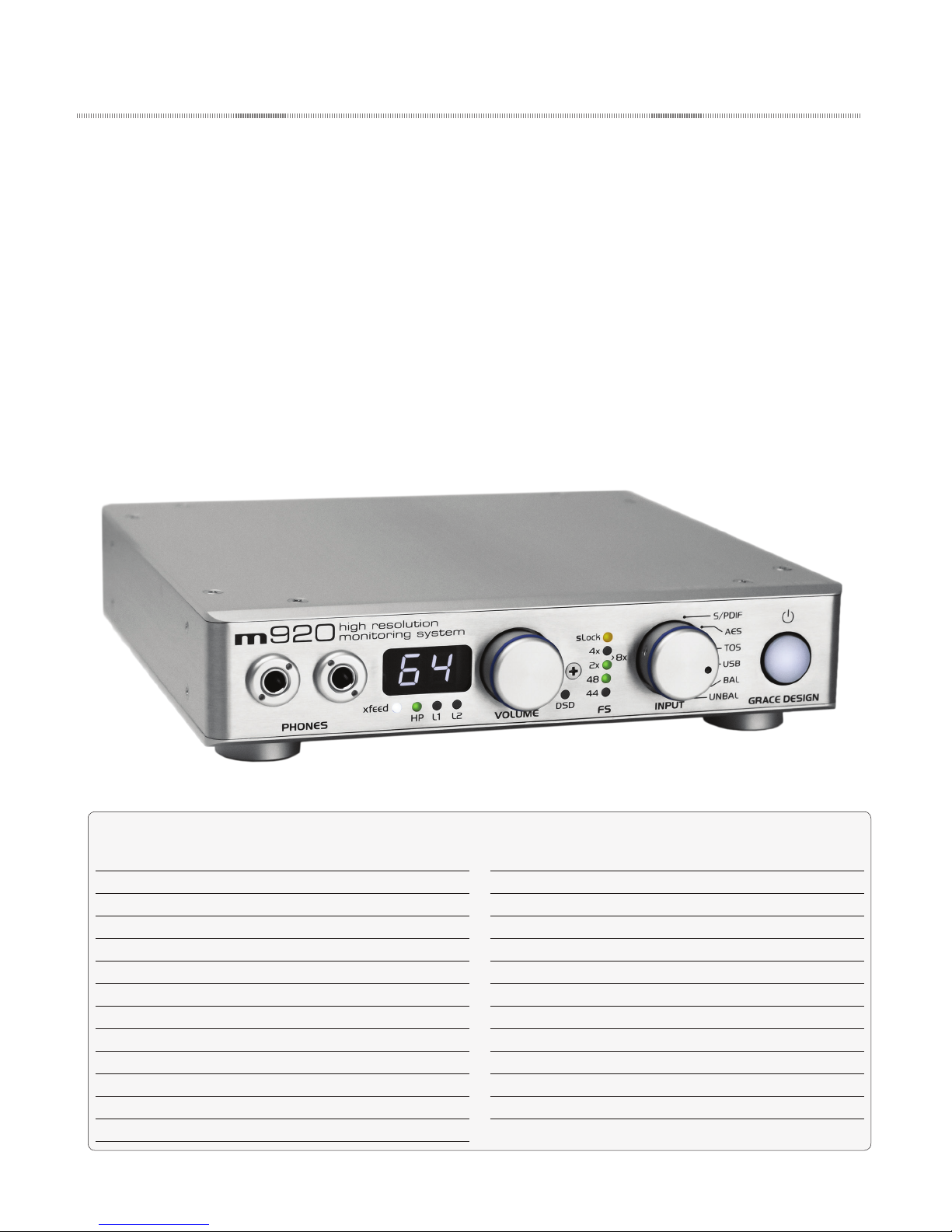
m920 Key Features
• Stereo analog inputs - balanced (+4dBu) XLR and
unbalanced (-10dBv) RCA.
• Ultra low distortion 32-bit /384khz Sabre DAC
accepts stereo digital input sources in AES3,
S/PDIF, TOSLINK (optical) and USB formats with
auto sample rate detection and digital de-emphasis lter
• User congurable DAC lter response for PCM
and DSD playback
• USB for playback of up to 384kHz / 32 bit PCM as
well as DSD64 and DSD128 playback via DoP
• AES and S/PDIF playback of up to 192kHZ / 24bit
PCM as well as DSD64 playback via DoP
• New dual-stage wide lock range PLL for improved jitter rejection on non s-locked sources
• Third generation s-Lock™ dual stage PLL (phase
lock loop) circuitry for the ultimate in low jitter
clocking and sonic integrity
• Two sets of line level outputs provided via RCA
(unbalanced) and ¼ TRS jacks (balanced) for connection to stereo monitors
• RCA line outputs can be congured for variable
or xed DAC output mode for operation as a
page 3
standalone digital to analog converter
• Front panel rotary encoder provides precision
level control of both headphone and the line
output levels. Level adjustments are made in
0.5dB steps within a 95dB range
• 0.05dB channel level matching to ensure true
stereo balance at any monitoring level
• High current transimpedance output amplier
design drives 8 ohm loads. The m920 was specically designed with low impedance headphones
in mind
• Only the highest quality 0.5% metal lm resistors
are used throughout and there are no electrolytic capacitors in the signal path. Sealed gold
contact relays are used for all signal switching
• Large, white 7-segment display is used to show
headphone and stereo main output levels
• Infrared remote control for level control, left/
right balance, mute and more when using the
• New X-feed (crossfeed) simulates the acoustics
optional remote control unit
of a loudspeaker listening environment which
can signicantly improve imaging while reducing listening fatigue when using headphones.
This feature employs carefully designed signal
cross-feed, ltering and delay circuits to simulate
• Apple IR remote control is supported with optional pairing
• USB rmware upgradability
• 5 Year transferable warranty on parts and labor
HRTF (head related transfer functions)
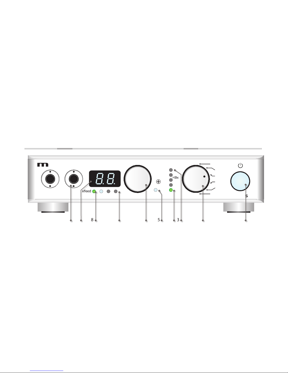
m920 Front Panel Controls / Features
920
PHONES
1 ILLUMINATED POWER SWITCH
high resolution
monitoring system
xfeed
10
HP
L1 L2
VOLUME
illuminates white
when unit is powered on.
2 ROTARY INPUT SELECTOR SWITCH selects be-
tween all available inputs.
3 S-LOCK™ INDICATOR LED illuminates when s-
Lock™ is active.
4 SAMPLE RATE INDICATOR LEDS auto sample rate
detection from selected digital input source.
LEDS indicate the base sample rate with the appropriate multiplier for 2x, 4x and 8x rates.
5 DSD INDICATOR LED auto DSD detection from
the selected digital input source
6 VOLUME / EDIT ROTARY ENCODER This stepped
rotary encoder controls the selected output
level in .5dB increments. This encoder is also
used to adjust other settings found in the setup
menu.
S/PDIF
sLock
4x
8x
2x
48
44
DSD
7 OUTPUT SELECTION LEDS These LEDS indicate
FS
INPUT
AES
TOS
USB
BAL
UNBAL
GRACE DESIGN
1345689 27
which output is currently selected for volume
control.
8 CROSSFEED INDICATOR LED Crossfeed circuitry is
user activated in the setup menu or via optional
wireless remote control.
9 OUTPUT LEVEL / SETUP MENU DISPLAY This white
2 digit display shows the current relative output
level values based on the position of the main
level rotary encoder. The range of this display is
0 to 99. Note the decimal represents a +0.5dB
increment. This display is also used to give the
user information in the setup menu.
10 HEADPHONE OUTPUTS Two stereo headphone
output jacks wired in parallel.
page 4
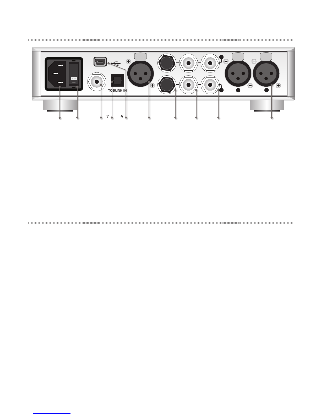
m920 Rear Panel
2
PUSH
1
3
USB IN
S/PDIF IN
TOSLINK IN AES3 IN
10
1 BALANCED ANALOG INPUT standard female XLR
connectors.
2 UNBALANCED ANALOG INPUT standard RCA
connectors.
3 UNBALANCED LINE OUTPUT standard RCA
connectors.
4 BALANCED LINE OUTPUT standard 1/4” TRS
connectors.
5 AES DIGITAL INPUT use 110 Ohm balanced
LINE OUT 2
PUSH
L
UNBAL INLINE OUT
1
R
1
2
3
R
BAL IN
PUSH
2
3
L
1345689 27
cable.
6 USB DIGITAL INPUT standard USB type A -to-
type B mini cable included.
7 TOSLINK DIGITAL INPUT standard TOSLINK opti-
cal cable.
8 S/PDIF DIGITAL INPUT use 75 Ohm cable.
9 AC LINE VOLTAGE SELECTOR selects beteen 100-
120VAC and 220-240VAC operation.
10 AC LINE INPUT MODULE standard 3 prong AC
cable included.
1
Unpacking and Installing your m920
The m920 is shipped in one box which contains the
m920 unit, an AC power cord, a USB cable, a small
plastic bag containing four hand-threaded machined
metal feet and a warranty registration card.
OPEN AND INSPECT THE BOX
Open all shipping boxes, carefully remove the m920
and put it aside. Before you go any further, check to
make sure the above listed components are included
with your shipment. If you believe something is
missing, contact your Grace Design dealer and they
will make sure you’re taken care of.
SAVE YOUR BOX!!
We strongly encourage you to save the box and
shipping materials supplied with your m920. They
are specially designed to properly protect these
valuable components, and in the unlikely event that
you need to return them for service, only these OEM
shipping materials can ensure their safe return to our
factory.
REGISTER YOUR UNIT!
We strongly urge you to register your unit with
Grace Design. We provide a limited 5 year transferable warranty on all of our products, but if you
register your system, it’s easier for us to help you if
necessary. So please take a few minutes to complete
the enclosed warranty registration card and mail it
in, or you can simply go to the warranty registration
form on our web site. We do not share your information with anyone. Thank you!
INSTALLING THE FEET
The m920 is designed to either be placed on a at,
stable surface in your studio or listening environment, or be rack mounted. If you don’t plan to rack
mount your m920, rst install the 4 supplied metal/
rubber feet. Simply thread the supplied feet by hand
into the 4 vacant threaded holes in each corner of
the underside of the m920.
RACKMOUNTING
For rack mount installation, the m920 chassis has a
#10-32 threaded insert mounting hole on the bottom
page 5
towards the back. Two m920’s can be mounted side
by side in a standard 1U rack tray. Use the supplied
Powering up the m920
#10-32 x 3/8” machine screw. Do not use a screw
longer than 3/8”.
POWER CONNECTIONS
The disconnect device for the m920 system is the
mains plug or the appliance coupler on the power
supply cord. The disconnect device must remain
accessible and operable. The power supply cord supplied with the m920 must be connected to a mains
outlet with a protective earthing connection.
CHECK LINE VOLTAGE SETTINGS
The IEC power entry module has been set from the
factory to operate at the voltage required for your
part of the world. However, it’s important to doublecheck this in order to ensure no damage will come
to the unit if power is applied and the setting is
incorrect.
LINE VOLTAGE SELECTOR
To change the line voltage, remove the AC power
chord from the power inlet then use a small screwdriver to pry the fuse carrier out. Remove both fuses
from the fuse carrier and replace with the proper
value fuse from the fuse chart below. Carefully
remove the grey colored fuse holder and re-insert
it into the fuse carrier with the proper line voltage
showing through the small window. Note that time
delay or “slow blow” fuses are required.
Voltage and Fuse information
CAM SETTING LINE VOLTAGE FUSE VALUE
110V~ 100-120V~ 250V~ T 250mA L
220V~ 220-240V~ 250V~ T 125mA L
fuse value table
AC POWER CORD
Connect the supplied AC cord to the iec
power entry module on the rear panel
of the m920. For safety, it is recom-
mended that the cable be connected to
a grounded
outlet.
LOW VOLTAGE DETECTION
The m920 will automatically detect a low line voltage condition. In the event that line voltage drops
below 85 VAC (for 100 -120 VAC) or 170 VAC (200
– 240VAC), the m920 will switch into low voltage
detection mode. In this mode both headphone and
line outputs are muted, and the 7 segment led will
begin to ash. The m920 will automatically return to
the previous operating state when proper line voltage is restored.
POWER-UP SEQUENCE
The m920’s headphone outputs are protected
from any popping when the unit is turned on or o.
However, if you are using the line outputs, observing proper power sequencing is recommended to
avoid any potential popping in your speakers. Before
powering up your m920, make sure your monitor
speakers or power amps connected to your monitors are turned OFF. Once the m920 and the rest of
your audio system are powered up, then turn on the
power to your speakers or ampliers. When powering
down, rst power OFF your speaker system and / or
power amps and then power down the m920. Turn
power amps on last, turn them o rst!
Input Connections
The input / output / interface connections highlighted earlier in this manual are detailed below.
Please contact us if you have any questions regarding
cable terminations or pinout specications.
BALANCED ANALOG INPUTS The balanced stereo an-
alog input is provided via female XLRs. Connection is
made using standard balanced XLR cables. This input
is wired pin 1 shield, pin 2 positive pin 3 negative.
UNBALANCED ANALOG INPUT This stereo input is
page 6
provided for interfacing with consumer level (-10dBv)
unbalanced analog sources. Connections are made
using standard RCA cables.
AES3 DIGITAL INPUT The stereo AES3 input is pro-
vided via one female XLR connector. This conforms
to the AES3 standard. Use of high quality 110 Ohm
balanced cable is highly recommended.
S/PDIF COAXIAL INPUT Standard coaxial stereo
digital input. The input impedance is 75 Ohms. Use a
quality 75 Ohm cable for connections to this input.
pin 3
pin 1
pin 2
TIP
RING
SLEEVE
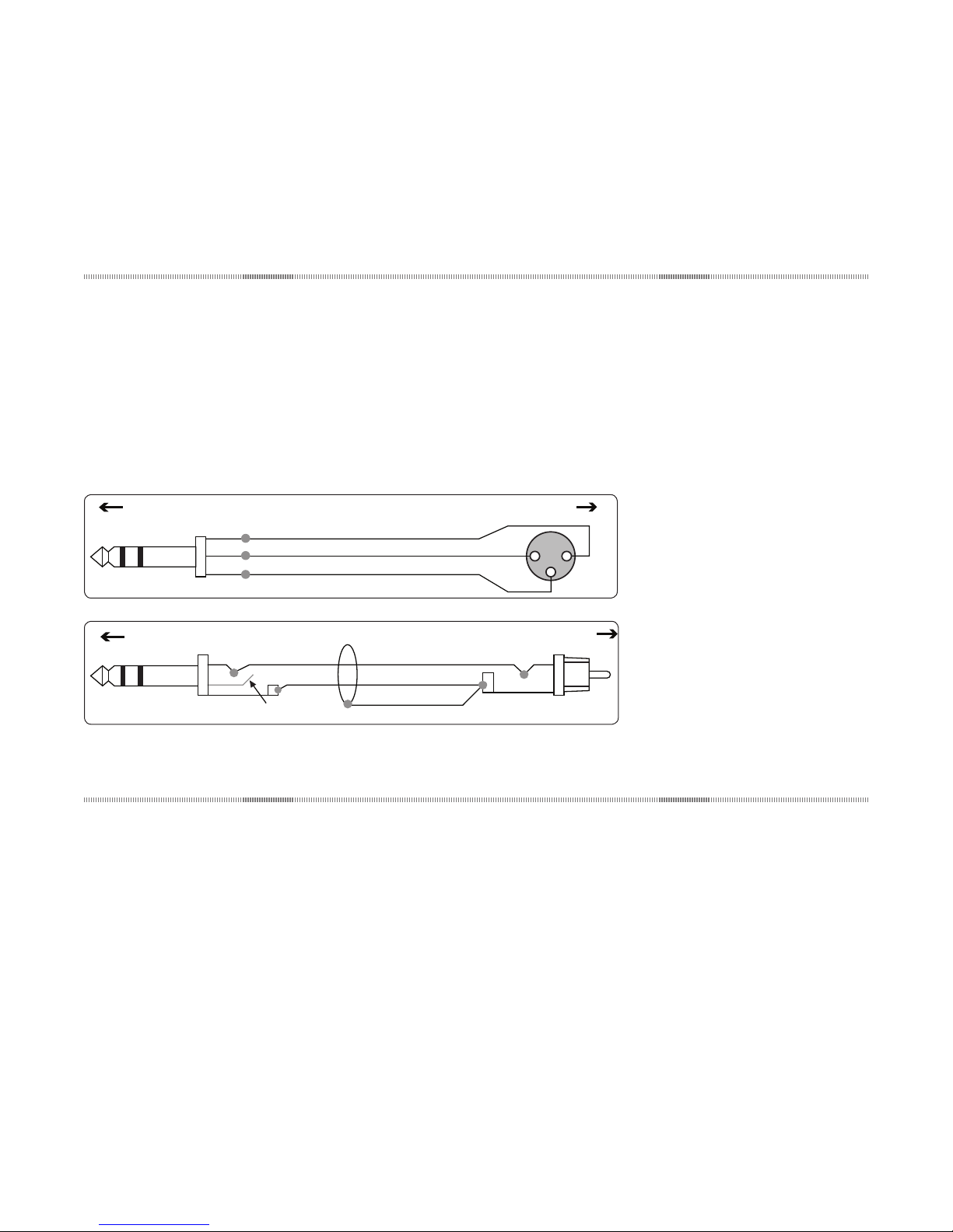
Balanced Input XLRBalanced Output 1/4” TRS
SHIELD
HOT
GND
RING IS OPEN
TIP
RING
SLEEVE
Unbalanced Input RCA
Balanced Output 1/4” TRS
TOSLINK INPUT Standard stereo optical input con-
nector for use with consumer devices. Use a standard TOSLINK optical cable for connections to this
input.
USB INPUT The stereo USB input for connection
Output Connections
to a host computer. Use a USB 2 (high speed) type
A -to- type B mini cable (included with your m920).
The type A connector is to be plugged in to the HOST
PC and the type B mini connector is to be used with
the m920 input. Due to the very high speed operation of this interface we recommend a 6ft (1.8 meter)
maximum length for this cable.
STEREO HEADPHONE OUTPUTS Headphone outputs
are provided via two ¼” TRS (Tip, Ring, Sleeve) jacks.
These outputs are wired in parallel. Connection to
headphones should be made using standard ¼” TRS
stereo connectors.
UNBALANCED LINE OUTPUTS A stereo pair of unbal-
anced line level outputs are provided via two RCA
jacks. These outputs should be connected to powered speakers, a preamplier, or power ampliers
using standard unbalanced RCA cables.
BALANCED LINE OUTPUTS A stereo pair of balanced
line level outputs are provided via two ¼” TRS jacks.
These outputs should be connected to powered
speakers, a preamplier, or power ampliers using
standard balanced cables. Connection to an unbalanced input is also possible. See diagrams below for
proper termination.
Selecting an Input Source
The m920 allows for selection from a variety of
analog and digital input sources. The rotary input
selector switch is used to choose the input source for
both the headphone amplier and line outputs.
ANALOG INPUTS
The m920 provides both balanced and unbalanced
stereo inputs. To select either of these analog inputs,
rotate the input selector to the desired input. When
an analog input is selected, the m920’s internal DAC
is turned o.
DIGITAL INPUTS
The m920 provides the following digital input
sources: AES3, S/PDIF, TOSLINK and USB. The AES3
and S/PDIF inputs support PCM audio data with
sample rates from 44.1kHz to 192kHz / 24 bit as well
as DSD64 via DoP. The TOSLINK input supports PCM
audio data with sample rates 44.1kHz to 96kHz /
24bit. The USB input supports PCM audio data with
sample rates from 44.1kHz to 384kHz / 32bit in addition to DSD64 and DSD128 via DOP.
page 7
 Loading...