

Page 1
m908 Preliminary User Manual, Rev. 04
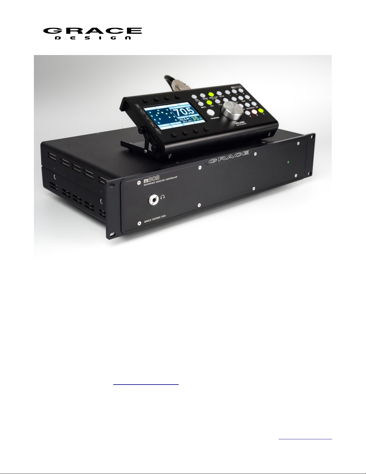
m908 multi channel monitor controller
PRELIMINARY
Entries marked ** are still to be defined.
Owner's Manual – Revision 01 / Feb 2019
RCU Firmware version: 0.01
ACU Firmware version: 0.01*
Grace Design, Lyons, CO / 1.303.823.8100
www.gracedesign.com / info@gracedesign.com
Page 1 of 108 Table Of Contents
Page 2

Table of Contents
m908 Preliminary User Manual, Rev. 04
1 Welcome...................................................................4
2 Important Safety Information...................................4
2.1 General...................................................................4
2.2 Safety Marking Symbols.......................................4
2.3 Service Information...............................................4
2.4 California Proposition 65 Warning........................5
3 Overview And Features............................................5
3.1 Features..................................................................5
3.2 ACU Description...................................................6
3.3 ACU Front Panel Connections and Controls........8
3.4 ACU Rear Panel Connections...............................8
3.5 RCU Description.................................................11
3.6 RCU Front Panel Controls...................................11
3.7 RCU Rear Panel Connections.............................13
3.8 RCU Tilting Base................................................13
3.9 PSU Description..................................................14
3.10 PSU Front Panel Controls and Indicators.........14
3.11 PSU Rear Panel Connections............................14
4 Installation..............................................................15
4.1 Unboxing your m908...........................................15
4.1.1 Open and inspect your box.........................15
4.1.2 Your box will contain..................................15
4.1.3 REGISTER YOUR UNIT...........................16
4.2 Connecting the m908...........................................16
4.2.1 Power Connections.....................................16
4.2.2 Audio Connections......................................16
4.2.3 Optional ADC Module Connections...........17
4.2.4 Clock and Control Connections..................17
4.2.5 Thermal Management.................................18
5 Operation................................................................19
5.1 Manual conventions.............................................19
5.2 Home Screen........................................................20
5.2.1 1 Input Selection.........................................20
5.2.2 2 Control Room Speakers Layout Icons.....20
5.2.3 3 Control Room Speaker Output................21
5.2.4 4 Control Room Monitor Level..................21
5.2.5 5 Headphone Crossfeed..............................21
5.2.6 6 Headphone Monitor Level.......................21
5.2.7 7 SPL Meter................................................21
5.2.8 8 Clock Source and Status..........................22
5.2.9 9 System Sample Rate.................................22
5.3 INPUT SELECT..................................................22
5.3.1 Input Summing Mode.................................23
5.4 DIM......................................................................23
5.5 X-FEED...............................................................23
5.6 MONO / (L-R).....................................................25
5.7 MON>CUE..........................................................25
5.8 MUTE..................................................................26
5.9 CR1, CR2, CR3...................................................26
5.10 BASS MANAGEMENT...................................26
5.11 ROOM CORRECTION.....................................27
5.12 TALKBACK......................................................28
5.13 SOLO/MUTE....................................................31
5.14 VOLUME (push for phones).............................32
5.15 A B C User Switches.........................................33
5.16 Monitor Snapshots.............................................33
5.17 Meter Outputs....................................................34
5.18 **Downmix.......................................................35
5.19 Clocking.............................................................36
5.20 Word Clock In and Out......................................37
5.21 Error Messages..................................................38
5.21.1 ACU Over Temperature............................38
5.21.2 PSU Error..................................................39
5.21.3 Communication Error...............................39
5.21.4 Cooling Fan Error.....................................40
6 System Setup..........................................................40
6.1 Introduction.........................................................40
6.2 Workflow Setup...................................................42
6.2.1 Workflow Setup Main Screen.....................42
6.2.2 Select Workflow To Edit Screen.................43
6.2.3 Editing Workflow Screen............................44
6.2.4 Workflow Channel Setup Screen................45
6.2.5 Editing Workflow Rename Screen..............46
6.2.6 Editing Workflow Save and Exit................47
6.2.7 Editing Workflow Cancel............................48
6.2.8 Workflow Load...........................................49
6.2.9 Workflow Copy...........................................50
6.2.10 Workflow New..........................................51
6.2.11 Workflow Import From USB....................52
6.2.12 Workflow export to USB..........................54
6.2.13 Workflow delete........................................57
6.3 Setup....................................................................58
Page 2 of 108 Table Of Contents
Page 3

m908 Preliminary User Manual, Rev. 04
6.3.1 Navigating and Using the Setup Menus.....58
6.3.2 Standard Parameter Editing........................60
6.3.3 Standard Name Editing...............................61
6.3.4 Standard Channel Routing..........................63
6.3.5 Input Setup..................................................65
6.3.6 Dim setup....................................................67
6.3.7 CR1, CR2, CR3 Speaker setup...................68
6.3.8 Bass Management setup..............................71
6.3.9 **SOLO/MUTE Setup................................71
6.3.10 Room Correction setup.............................73
6.3.11 Monitor Control setup...............................74
6.3.12 MONO setup.............................................76
6.3.13 (L-R) setup................................................76
6.3.14 CUE setup.................................................77
6.3.15 MUTE setup..............................................79
6.3.16 User A B C Switches Setup.......................80
6.3.17 Downmix setup.........................................81
6.3.18 Monitor Snapshot setup............................81
6.3.19 Meter Output setup....................................82
6.3.20 Talkback setup...........................................84
6.3.21 SPL Meter setup........................................86
6.3.22 Clock Source Setup...................................87
6.3.23 Word Clock Termination Setup.................88
6.3.24 Word Clock Output Setup.........................88
6.3.25 *GPIO Setup.............................................88
6.3.26 System Setup.............................................91
7 Option Modules......................................................93
7.1 ADC Option Module...........................................93
7.2 Dante Option Module..........................................94
7.3 DigiLink Option Module.....................................94
7.4 Phono Preamp Option Module............................95
8 USB Audio Setup...................................................96
8.1 Computer Audio Requirements...........................96
8.2 Windows USB ASIO Driver................................97
8.2.1 Installing USB ADIO Driver......................97
8.2.2 Using The USB ASIO Driver.....................99
9 **Firmware Upgrades..........................................101
9.1.1 Firmware Update Procedure.....................102
10 Electrical Specifications.....................................102
11 Block Diagrams..................................................102
12 Cable and Connector Diagrams..........................103
13 Dimensions.........................................................106
14 Warranty Information.........................................107
15 Illustrations Index...............................................108
16 Manual Revision History....................................109
List of Tables
Clock Status...............................................................36
Speaker Names...........................................................42
Workflow Templates..................................................48
GPIO FUNCTIONS...................................................79
GPIO VOLTAGE CONFIGURATION.......................81
Page 3 of 108 Table Of Contents
Dante Channel Count.................................................85
DB25 Digital AES3 (Tascam Pinout).........................92
DB25 Analog (Tascam Pinout)...................................92
DB15 RCU Connector................................................93
Manual Revision History............................................98
Page 4
m908 Preliminary User Manual, Rev. 04
1 Welcome
Thanks for purchasing the m908 multi-channel monitor controller. It has been painstakingly
designed and built to provide you with a beautiful sounding, configurable and reliable monitoring
system. Please familiarize yourself with the setup and operational details contained in this
manual. And as always with this or any other Grace Design products, please don't hesitate to
reach out if you have any questions. We are available by telephone Monday – Friday, 9AM to
5PM MST, or by email at info@gracedesign.com. Also, other information including technical
documents and firmware can always be found on our website – www.gracedesign.com. Thanks
for reading and enjoy your m908!
2 Important Safety Information
2.1 General
• Indoor use only
• Ordinary Protection: This equipment should not be exposed to dripping or splashing.
• Avoid placing objects filled with liquids, such as vases or glasses, on this equipment.
• Class I Equipment (grounded type)
• Electrical rating: 90-240V~ 50-60Hz 40W
• Mains supply voltage fluctuations are not to exceed ±10% of the nominal supply voltage.
• Pollution Degree 2
• Installation (Over voltage) Category II for transient overvoltages.
• Maximum Relative Humidity: <80%
• Operation temperature range: 10 °C to 40 °C
• Storage and transportation temperature range –40 °C to 70 °C
• Maximum altitude: 3000m (9843 ft)
• Equipment suitable for continuous operation
2.2 Safety Marking Symbols
This symbol, located on the equipment and in this manual, refers to important instructions.
Read this manual thoroughly before operating this equipment.
This symbol, located on the equipment and in this manual, indicates the potential for
electrical shock hazard.
2.3 Service Information
Page 4 of 108 Table Of Contents
Page 5

m908 Preliminary User Manual, Rev. 04
The Grace Design m908 contains no user serviceable components. Contact Grace Design for
repair and upgrade information. In the event that your Grace Design m908 needs to be returned to
the factory, contact us for a return authorization number.
2.4 California Proposition 65 Warning
This product may contain metallic nickel, a chemical known to the State of California to cause
cancer and birth defects or other reproductive harm. Wash hands after handling.
3 Overview And Features
3.1 Features
• 24 Channel DSP for immersive surround formats such as ATMOS™, DTS:X™ and Auro 3D™
• Manage playback systems from mono through 22.2
• Our latest generation of AD and DA converters
• Powerful and ergonomic remote control unit for access to all system controls
• 4th generation s-Lock pll clocking system for vanishingly low jitter
• High resolution volume control
• Up to 1 second sync delay
• Room correction EQ
• Full bass management
• Speaker channel level and delay calibration
• Comprehensive downmix control
• 16 channel analog out / 24 channel AES3 digital I/O
• 16 channel ADAT Lightpipe In / USB 24 channel In
• AES3, S/PDIF, and TOSLINK Stereo In
• Optional Dante™, DigiLink™ or MADI module for additional 32 channel I/O
• Optional 8 channel ADC module for 8 or 16 channel analog inputs
• Optional high performance RIAA phono preamplifier for MC and MM cartridges.
• Flexible Meter outputs
• Built in SPL meter
• Dual redundant external power supply
• Reference quality headphone amplifier with cross-feed.
• Flexible talkback system with built-in mic on remote control and mic input for external talkback
mics
• Up to 8 stereo CUE paths
• 4 General Purpose Input and Output pins for interfacing to external systems.
Page 5 of 108 Table Of Contents
Page 6

m908 Preliminary User Manual, Rev. 04
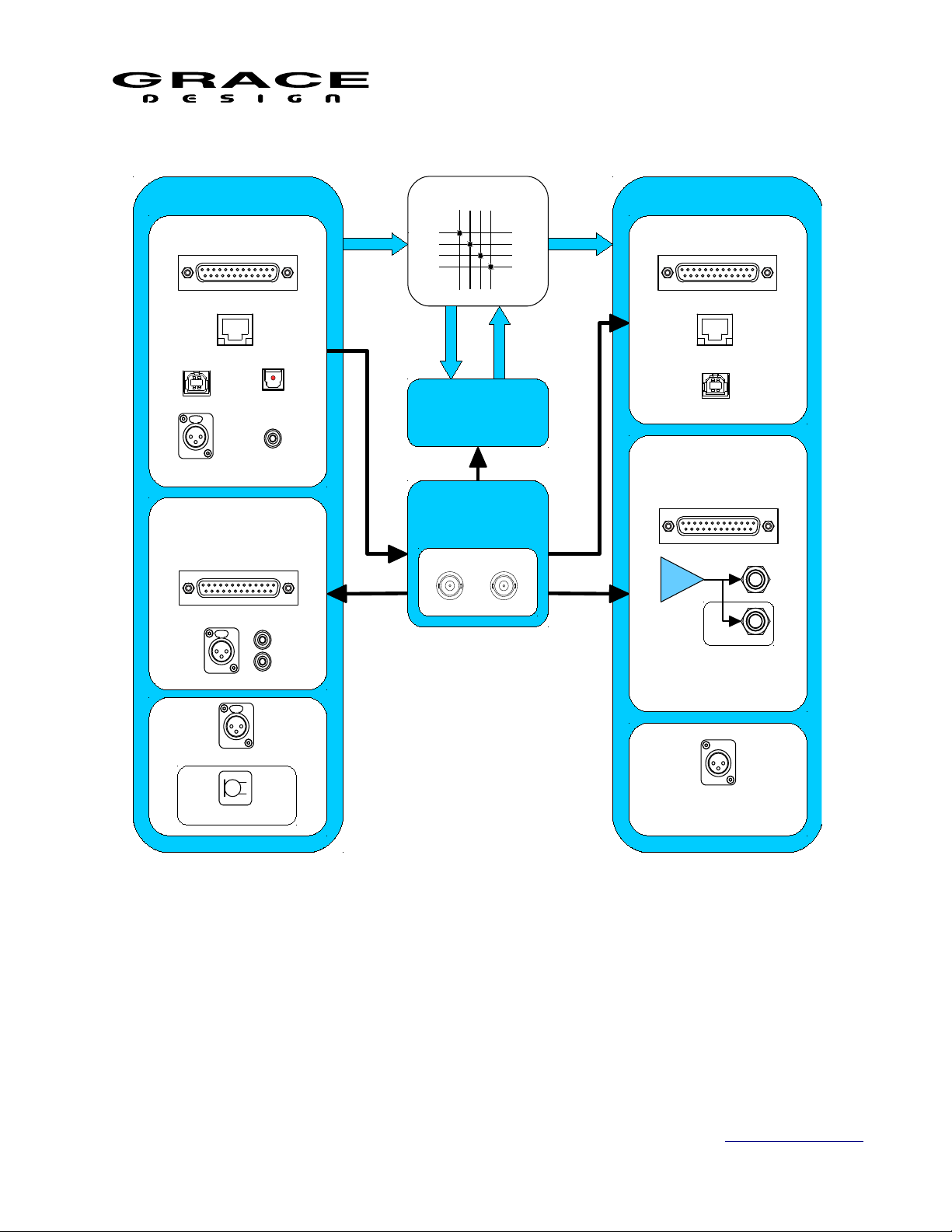
The m908 consists of three components: ACU (Audio Control Unit), RCU (Remote Control Unit), and
PSU (Power Supply Unit) Below is a description of the connections, controls, and indicators for each
component.
3.2 ACU Description
The 2U ACU chassis houses all of the analog and digital audio IO, DSP processing, and
control IO. The audio signal processor is a 1GHz 32 bit floating point unit which allows for
highly accurate and low latency signal processing. 2GB of DDR2 ram allows for ample sync
delay across 24 channels at sample rates up to 192kHz. Audio routing, AES and ADAT encoding
and decoding is handled by an Artix-7 FPGA. The system is managed by an ARM Cortex-A15
processor running embedded Linux.
The m908 system clock is based on our 4th generation s-Lock PLL technology. This is an
incredibly low jitter PLL that provides exceptional ADC and DAC sample clocking accuracy.
The Audio and Clock flow is shown in the simplified block diagram below.
Page 6 of 108 Table Of Contents
Page 7
m908 Preliminary User Manual, Rev. 04
AUDIO INPUTS
ROUTING
DSP
ADC OPTION
ANALOG 16CH
ANALOG 2CH
AUDIO OUTPUTS
DAC
ANALOG 16CH
HP AMP
RCU
DIGITAL OUTPUTS
AES DIGITAL 24CH
USB 8CH
DANTE 32CH
CLOCK
s-Lock PLL
WORD CLOCK I/O
IN OUT
ACU TALKBACK
RCU TALKBACK
DIGITAL INPUTS
AES DIGITAL 24CH
USB 24CH
ADAT 16CH
(TOSLINK 2CH)
DANTE 32CH
SPDF 2CH
AES 2CH
TALKBACK OUT
Illustration 1: Audio and Clock Flow Diagram
The audio signal processing signal flow is shown in the diagram below.
Page 7 of 108 Table Of Contents
Page 8
m908 Preliminary User Manual, Rev. 04
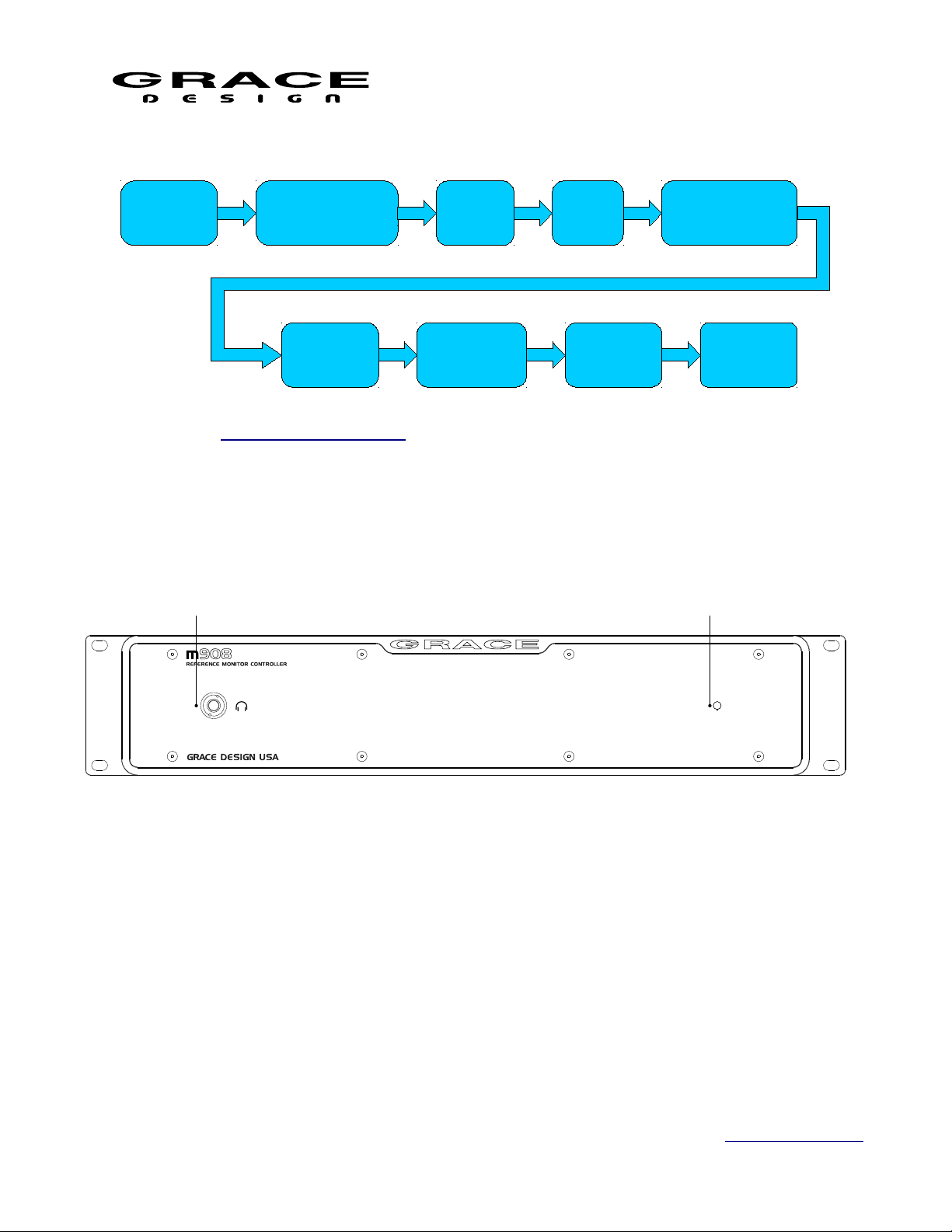
1 2
AUDIO
INPUTS
INPUT SELECT
AND SUMMING
SPEAKER
DELAY
LEVEL
OFFSET
SPEAKER
LEVEL
OFFSET
Illustration 2: audio path flow diagram
3.3 ACU Front Panel Connections and Controls
SYNC
DELAY
SPEAKER
VOLUME
BASS
MANAGEMENT
AUDIO
OUTPUTS
Illustration 3: ACU Front Panel
1. 1/4" Headphone Jack: The m908 headphone amplifier is an ultra high performance current
feedback design. Very low output impedance ensures good damping factor at the headphone
driver. The proprietary crossfeed circuit provides natural imaging and minimizes listening
fatigue.
2. Power indicator LED: Green LED illuminates solid green under normal conditions. Flashing
indicates a fault contrition in the redundant power supply unit.
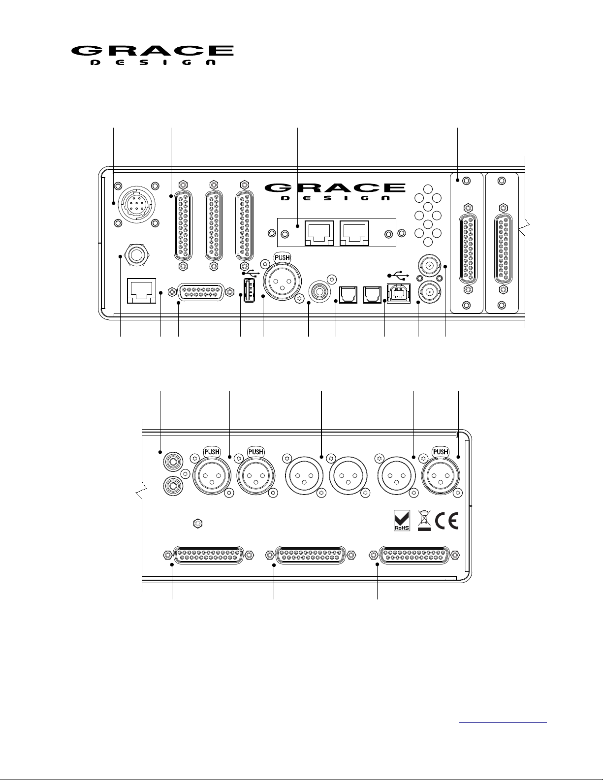
3.4 ACU Rear Panel Connections
Page 8 of 108 Table Of Contents
Page 9
m908 Preliminary User Manual, Rev. 04
1 2
1
2
3
5
86
DC IN
A140-M908
PSU ONLY
TALKBACK SWITCH
ETHERNET
10 11
5 6 7 8 9
3 4
ADC 2
A
E
S
3
3
I
N
/
O
U
T
1
4
A
E
S
3
2
I
N
/
O
U
1
T
m908 RCU
A
E
S
3
1
I
N
/
O
U
T
1
1
4
1
9
m908 REFERENCE MONITOR CONTROLLER
1
1
4
HOST
AES3 IN
OPTION I/O
S/PDIF
OPTICAL IN AUDIO
WC OUT
2
1
WC IN
12 13 14 15 16 17 18 19
A908
ADC
A
N
A
L
O
G
I
N
1
-
8
1
4
A908
ADC
A
N
A
L
O
G
I
N
1
-
8
1
1
1
4
ADC
1
L
R
UNBAL IN
BAL IN
L L
R CR 3 OUT R
TB INTB OUT
MADE IN LYONS, CO USA
CR 1 OUT CR 2 OUT
1
14
- 8
(1
)
- 8
(1
) (
1
14
CUE/CR EXT.
9 - 16
)
1
14
20 21 22
Illustration 4: ACU Rear Panel
1. DC power input connector 8 Pin Circular: Connect to PSU. CAUTION: CONNECT PSU TO
ACU WITH DC POWER CABLE BEFORE APPLYING POWER.
Page 9 of 108 Table Of Contents
Page 10

m908 Preliminary User Manual, Rev. 04
2. AES3 I/O x 3 DB25 (Tascam pinout) 110Ω: 24 channel input and output. Accepts sample rates
from 44.1kHz-192kHz.
3. Option I/O slot (Dante , Digilink, and MADI options): The Option I/O module can receive and
transmit 24 channels of PCM audio.
4. Analog balanced input ADC (optional): There are slots for two optional 8 channel ADC
modules with DB25 input connectors. The ADC modules plug in to the main digital pcb. Two
ADC modules can be used for a total of 16 channels. The ADC in position 1 is also connected
to the stereo balanced XLR and unbalanced phono jacks so that it can be used for monitoring
stereo sources on channels 1-2. Note that when monitoring the stereo connections, channels 1-2
on the DB25 connector are not heard.
5. Stereo Input analog unbalanced RCA Phono: Present if an ADC option module is installed. Can
be switched to Phono level if the RIAA Phonograph Preamplifier module is installed.
6. Stereo Input balanced analog XLR: Present if an ADC option module is installed.
7. Control Room 3 Output balanced analog XLR: Analog output signals sourced from DAC
channels 1-2.
8. Talkback output balanced analog XLR: Talback signal sourced from ACU or RCU Mic. Can be
configured to be momentary while talkback is active or continuously on.
9. Talkback mic input balanced XLR: Balanced microphone level input with available 48V
phantom power. The talkback signal is fed to an ADC and sent to the DSP section and also sent
to the Talkback output XLR connector. This is a full featured high performance microphone
preamplifier that can be used for recording and voice over applications.
10. External Talkback switch jack 1/4" TRS: Wiring a normally open switch to this jack will allow
for another talkback control. The Ring of this connector carries current limited 5V for
powering a tally LED. See Cable Diagrams.
11. Ethernet Control Port RJ45: Reserved for future use.
12. RCU serial control DB15: Connect to RCU with supplied DB15 cable.
13. USB Host USB-A: USB host connector for system firmware update.
14. AES3 Input XLR: Stereo AES digital input. Supports sample rates from
15. SPDIF Input RCA Phono
16. ADAT/TOSLINK x 2 Optical: Optical receivers for ADAT or TOSLINK. Supports SMUX for
8ch 96kHz operation.
17. USB Audio I/O USB-B: The USB Audio Class 2 compliant interface allows for monitoring up
to 24 channels of PCM audio at 48kHz/24bit and 8 channels of PCM audio at 192kHz/24bit.
18. Word Clock IN BNC 75Ω or 47kΩ (setup menu selected): External clock input.
19. Word Clock OUT / THROUGH BNC 75Ω: Output clock signal can be a buffered copy of the
incoming word clock or can be from the internal word clock.
Page 10 of 108 Table Of Contents
Page 11

m908 Preliminary User Manual, Rev. 04
20. Control Room 1 output balanced analog DB25 (Tascam pinout): Analog output signals sourced
from DAC channels 1-8.
21. Control Room 2 output balanced analog DB25 (Tascam pinout): Analog output signals sourced
from DAC channels 1-8
22. CUE/WIDE OUT balanced analog DB25 (Tascam pinout): Analog output signals sourced from
DAC channels 9-16. These outputs can be for speakers in immersive playback systems or for
CUE outputs. CUE outputs have level control, assignable talkback summing, and MON>CUE
routing. MON>CUE sends the Left and Right signal from the current monitor signal to the
CUE output. In the case of multi-channel monitoring the Left and Right signal or a stereo
downmix can be sent to the CUE output.
3.5 RCU Description
The Remote Control Unit is designed to be a seamless interface between the user and the
audio system being controlled. We have carefully selected the display, switches, and encoder to
be long life and provide excellent tactile feedback. All of the necessary information is displayed
on the 1/4WVGA display while the most used functions have dedicated switches. There is a 1/4"
headphone jack on the rear of the RCU for convenient access to the m908s high performance
headphone amplifier.
The RCU sits on a tilting base so it can be adjusted to the most comfortable angle. The built in
talkback microphone on the RCU also doubles as an accurate sound pressure level (SPL) meter.
The RCU is powered from the ACU via the DB15 cable.
3.6 RCU Front Panel Controls
Many of the most used monitoring functions are directly accessed through the push button
switches on the RCU front panel. Primary functions are accessed with a press-release. Where a
switch has more than one function the primary function is indicated with large upper case letters.
The secondary function is indicated in small letters and is accessed with a push-hold of the
switch. Some switches can have secondary functions assigned to them by the user. These
switches do not have lower case labeling.
Page 11 of 108 Table Of Contents
Page 12

m908 Preliminary User Manual, Rev. 04
TALKBACK
VOLUME
push for phones
MUTE
SETUPMON > CUE
CR 2 CR 3
MONO
x-feed
DIM
spl clear
L - R
L C R
RSLS
SUB
RB
SOLO/MUTE
A
LB
B C
CR
1
21 3 4 7 8 9
10111213
5 6
14
Illustration 5: RCU Front Panel
1. LCD Display screen: This color LCD displays all operating parameters and setup menus.
2. INPUT Select switches (8x): These switches select the input source to be monitored. See Input
Select operation for details.
3. DIM (x-feed): Dims the monitor system by a pre-programmed level. Push-hold enables/disables
the headphone cross-feed circuit. See DIM operation for details.
4. MUTE: Mutes the monitor system. See MUTE operation for details.
5. MONO (L-R): Sums the Left and Right channels (L+R). Push-hold for difference (L-R). See
MONO operation for details.
6. CR1, CR2, CR3: Control Room Speaker system select. See CR1 CR2 CR3 operation for details.
7. MON > CUE (spl clear): Sends the current source being monitored to the CUE sends. Pushhold clears the maximum spl field in the sound pressure level meter. See MON>CUE operation
for details.
8. SETUP: System Setup access. Push-Hold for System Workflow setup. See System Setup and
Workflow Setup for details.
Page 12 of 108 Table Of Contents
Page 13
m908 Preliminary User Manual, Rev. 04
m908
ACU
1 2 3 4
9. L, C, R, LS, SUB, LR, LB, RB: Speaker select for SOLO or MUTE. See SOLO MUTE for
details.
10. SOLO/MUTE: Selects between SOLO and MUTE monitoring mode. See SOLO MUTE for
details.
11. A, B, C: User programmable switches. See A B C User Switches operation for details.
12. VOLUME: Monitor level control for Control Room speakers and headphones. See VOLUME
operation for details.
13. TALKBACK: Talkback is activated by pushing this switch. See TALKBACK operation for
details.
14. INPUT Select switch and Input Page change. See Input Select operation for details.
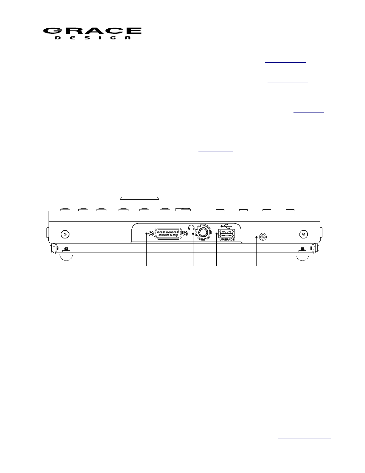
3.7 RCU Rear Panel Connections
Illustration 6: RCU Rear Panel
1. m908 ACU DB15: Serial control cable connection to ACU
2. Headphone Jack 1/4" TRS: Carries stereo headphone signal from ACU headphone amplifiers.
This jack is wired in parallel with ACU front panel headphone jack.
3. USB Host USB-A: USB host connection for user configuration export/import and RCU
firmware update.
4. Microphone: Built in mic for talkback and spl measurement
3.8 RCU Tilting Base
The RCU features a tilting base so that it can be tilted to an angle for optimal viewing. Loosen
Page 13 of 108 Table Of Contents
Page 14
m908 Preliminary User Manual, Rev. 04
A140 REDUNDANT DC POWER SUPPLY UINT
OK
PS #1 FAULT
PS #2 FAULT
CAUTIO N: CONNECT DC POWER CORD B EFORE T URNING ON PO WER
+18V
+6.5V +50V
-18V
1
2
the four thumbscrews located on each side of the RCU and tilt the unit to the desired angle.
While holding the RCU at this angle tighten the four thumbscrews. The tilt range is from
horizontal to 30º.
3.9 PSU Description
The m908 monitor controller is powered by the A140 Dual Redundant Power
Supply Unit. The A140 features Universal AC Input for operation from 100240VAC. This new generation external power supply contains two complete power
supply modules which operate in parallel. Should one power supply module fail
the other module will continue to power your system with no interruption. The A140 contains an
intelligent microprocessor that monitors all of the DC rail voltages and reports fault conditions by
flashing front panel LEDs. In the unlikely event that a power supply module fails the A140 front
panel LEDs with flash to indicate which power supply module is at fault. The power supply
modules are easily replaced in the field which minimizes any possible system down time.
A low speed serial communication link allows the power supply unit to communicate voltage
rail status to the main ACU processor.
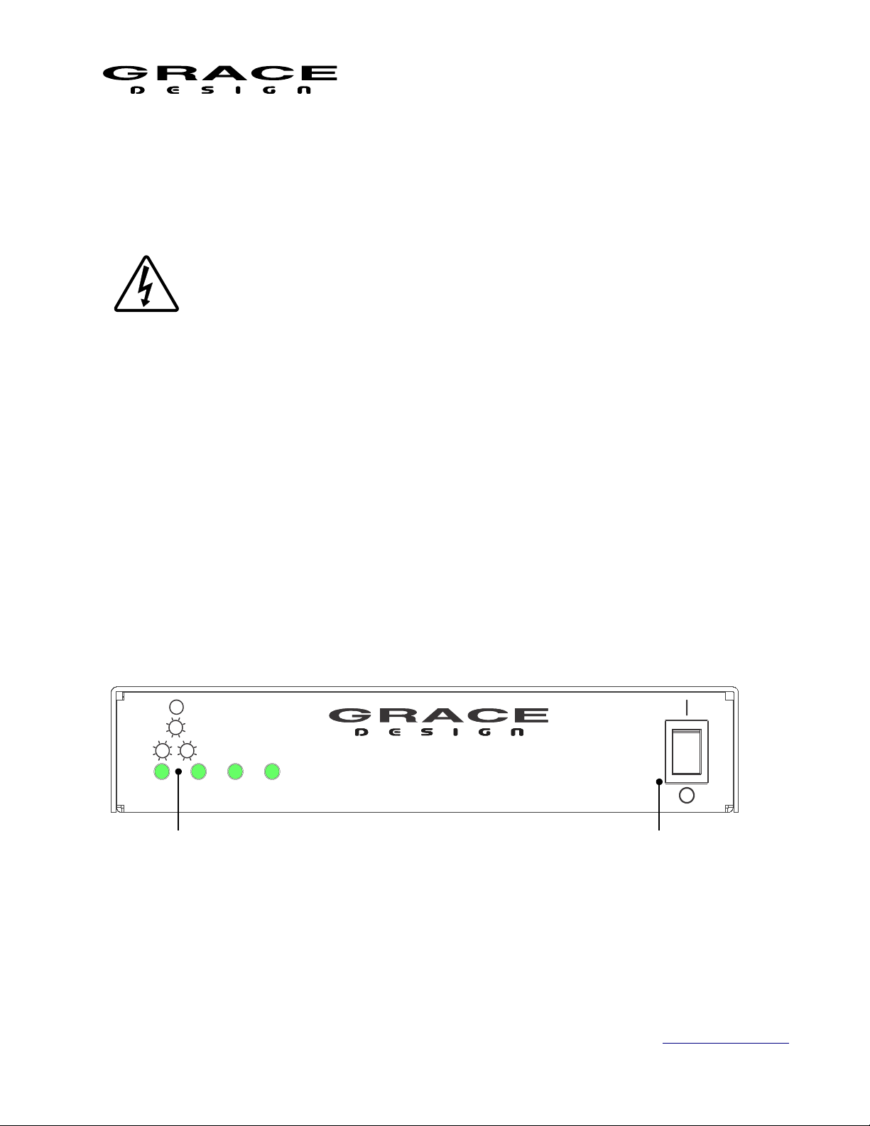
Under normal operating conditions the four front panel Status LEDs will be solid green.
If a DC output of power supply module #1 becomes too low or too high the corresponding LED
will flash once repeatedly. If a DC output of power supply module #2 becomes too low or too
high then the corresponding LED will flash twice repeatedly. If this happens contact Grace
Design Technical Support at 303-823-8100 x105 or service@gracedesign.com
3.10 PSU Front Panel Controls and Indicators
Illustration 7: PSU Front Panel
1. Voltage rail monitor LED x 4: These LEDs will illuminate steady green under normal operation.
2. Mains power switch: This is the AC Mains disconnect device. It must remain accessible.
Page 14 of 108 Table Of Contents
Page 15
m908 Preliminary User Manual, Rev. 04
A140-m801
A140-m802
A140-m906
A140-m908
MADE IN USA
100-240VAC
50W MAX
2 31
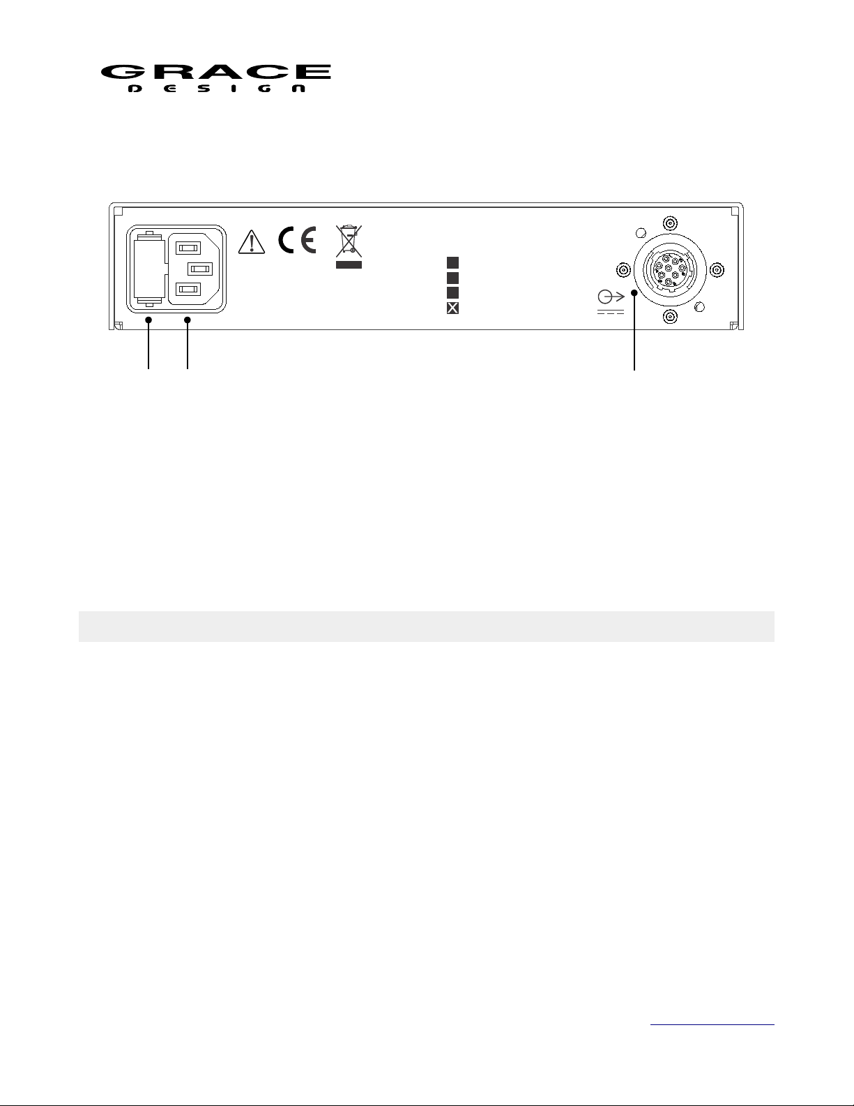
3.11 PSU Rear Panel Connections
Illustration 8: PSU Rear Panel
1. Fuse drawer: Contains (2) 5x20mm 800mA Time Delay fuse.
2. AC Power inlet: 90-240V~ 40W max. Connect to a grounded outlet.
3. DC Output connector: ALWAYS connect DC power cable to m908 before turning on power and
turn off the power before disconnecting the DC power cable!
4 Installation
4.1 Unboxing your m908
4.1.1 Open and inspect your box
Please take care when removing the m908 from its OEM packaging. Our packaging is
designed with ‘Korrvu©’ suspension inserts, which provide the best protection from the dubious
underworld of freight handling – so save your packaging material. Inner boxes will contain all
the items listed below. If you think you are missing anything, give your dealer or us a call and
we’ll get you taken care of right away.
4.1.2 Your box will contain
• 1pc Audio Control Unit (ACU)
• 1pc Remote Control Unit (RCU)
• 1pc Power Supply Unit (PSU)
• 1pc AC power cord
Page 15 of 108 Table Of Contents
Page 16

m908 Preliminary User Manual, Rev. 04
• 1pc DC power cord 8’ (2.8m) (Grace Part No. WA084)
• 1pc DB15 Remote Cable, 25' (7.6m) (Grace Part No. WA141)
• 1pc USB 2.0 Cable, Type A to Type B, 6 foot (Grace Part No. WA551)
• 2pc spare fuses. 800mA 250V~ Time Delay 5x20mm (Grace Part No. F101, Littlefuse
0239.800HXP or equivalent)
• 4pc Adhesive backed rubber feet, 0.12" thick (Grace Part No. H560)
• 4pc Adhesive backed rubber feet, 0.23" thick (Grace Part No. H580)
• 4pc 10-32 X 3/4 Truss Head Phillips rack mount screw (Grace Part No. H455)
• 1pc m908 User Manual
4.1.3 REGISTER YOUR UNIT
We strongly urge you to fill out your warranty registration card. The m908 is covered by a 5
year transferable warranty. Registering your unit will help us contact you if there are important
updates and simplifies warranty service. So please take a few minutes to complete and send in the
enclosed card, or simply fill out the warranty registration form on our website. We always keep
your information private. Thank you!
4.2 Connecting the m908
4.2.1 Power Connections
A DC power cord is supplied to connect the PSU to the ACU. This cord can be
identified by the 8 pin circular connectors at each end.
Please note that the DC power cord should be connected before the AC power is turned
on. This prevents incorrect power sequencing which can cause damage to the audio circuits. To
avoid any interference with the low level audio circuitry, the power supply should be located at
least 3’ (1m) from the ACU.
WARNING: A damaged DC power cord can create a shock hazard as voltages of 72VDC can
be present.
Do not operate the m908 with a damaged DC power cord. If damage occurs, please contact
Grace Design for a replacement. A standard AC power cable is included. For safety, the power
supply cord must be connected to a grounded outlet.
4.2.2 Audio Connections
Talkback Microphone Input: Female XLR, pin 2 positive, pin 3 negative and pin 1 ground.
48V phantom power is supplied on pins 2 and 3. With a gain range +7dB and +15-70dB in 1dB
steps this inputs can be used for any type of microphone or as a line level input.
Talkback Microphone Output: Male XLR, balanced, pin 2 positive, pin 3 negative and pin 1
Page 16 of 108 Table Of Contents
Page 17

m908 Preliminary User Manual, Rev. 04
ground. Provides a direct output of the talkback microphone preamp.
Analog Balanced Control Room Outputs: DB25 Tascam pinout (See CABLE
DIAGRAMS). These outputs are defined in the setup menus for your control room speaker
system.
Analog Balanced CUE/WIDE Outputs: DB25 Tascam pinout (See CABLE DIAGRAMS).
Depending on your workflow these outputs are defined in the setup menus for your additional
surround/overhead speakers or CUE outputs.
Analog Balanced Stereo Control Room Output: Male XLR, balanced, pin 2 positive, pin 3
negative and pin 1 ground. These outputs are defined in the setup menus for your control room
speaker system.
AES3 Digital I/O: DB25 Tascam pinout, 110Ω (See CABLE DIAGRAMS)
ADAT Lightpipe / TOSLINK Inputs: In ADAT Lightpipe Mode these optical jacks provide
8 channels of audio data on each (at 44.1kHz and 48kHz). With ADAT S-MUX enabled 88.2kHz
or 96kHz sample rate audio channels 1-4 are received on OPTICAL input 1, while channels 5-8
are received on OPTICAL input 2. 176.4kHz and 192kHz sample rates are not supported over the
ADAT interface. In TOSLINK mode stereo signals up to 96kHz can be received on each
connector. See the System Setup section of this manual for details on configuring the optical
input connectors.
SPDIF Digital Stereo Input: RCA Phono jack, 75Ω. This input will receive PCM audio
signal sample rates from 44.1kHz to 192kHz.
USB Class 2 Audio Interface: USB Type B jack. This interface is capable of 24 channel
input from host computer and 8 channel output to the host computer. Use a standard USB type A
-to- type B cable (included with your m908). The type A connector is to be plugged in to the
HOST computer and the type B connector to the m908 input. PCM 44.1kHz – 192kHz/24 bit is
supported. Please refer to USB Audio Setup.
4.2.3 Optional ADC Module Connections
Analog Balanced 8 Channel Line Inputs: DB25 Tascam Pinout (see CABLE DIAGRAMS).
8 channel ADC module balanced inputs. Internal jumpers select input sensitivity of
+18dBu=0dBFS or +22dBu=0dBFS.
Analog Balanced Stereo Line Input: Female XLR, balanced, pin 2 positive, pin 3 negative
and pin 1 ground. Supplied with ADC Option Module. Allows for the connection of balanced
stereo sources to the ADC. Left channel is connected to ADC 1 channel 1 and Right channel is
connected to ADC 1 channel 2.
Analog Unbalanced Stereo Line Input: RCA Phono. Supplied with ADC Option Module.
Allows for the connection of unbalanced stereo sources to the ADC. Left channel is connected to
ADC 1 channel 1 and Right channel is connected to ADC 1 channel 2.
Page 17 of 108 Table Of Contents
Page 18

m908 Preliminary User Manual, Rev. 04
4.2.4 Clock and Control Connections
REMOTE CONNECTOR: DB15 The m908 RCU handles all system control. Connection to
the m908 RCU is via this DB15 connector, which carries RS485 serial data, DC power and
headphone signals. The m908 ships with a high quality 25’ cable. Custom cables can be
assembled by the user according to the diagrams in the Cable Diagram section of this manual.
While the serial data can travel over 1000 feet we do not recommend cables longer than 50’ for
headphone use. If you need a longer, cable contact your Grace Design dealer or us directly. Do
NOT use an off the shelf DB15 cable as the pinout will be incompatible and may cause damage
to your system.
WORD CLOCK IN: BNC 75Ω or 47kΩ (setup menu selected). The m908 can accept a
standard 5V/75Ω word clock signal from an external clock generating unit. This might be a
stand-alone clock source or via, for example, the word clock output from your digital audio
workstation. The m908 locks to the incoming word clock with an ultra low jitter PLL. The PLL
has a fast lock mode which rapidly acquires lock and then switches to a high jitter rejection mode
with a loop bandwidth of 0.5Hz. This provides exceptional jitter rejection for the DAC and ADC
sample clocks. In the event of a dropout or loss of incoming word clock signal, the intelligent
PLL will remain at the last known valid frequency. When the signal is restored the PLL will
smoothly re-acquire lock.
WORD CLOCK OUT: BNC 75Ω. The word clock output allows the user to synchronize
other digital audio equipment to the m908. When the system menu setting "clock output" is set to
external, this connector output is a buffered copy of the signal on the word clock IN jack. This
mode is useful for "daisy chaining" to other units in a system. When "clock output" is set to
system clock this connector outputs a buffered copy of the internal m908 word clock. The output
is buffered and is designed to drive a 75Ω line.
ETHERNET: RJ45. This is a standard 1000 Base-T Ethernet interface. Currently it is
reserved for factory diagnostics.
USB HOST: USB A connector. This host connector is intended for firmware upgrades.
EXT. TALKBACK: 1/4" TRS Jack. External talkback control. This input allows the
connection of an external switch, such as a footswitch, for remotely activating the ACU talkback
mic input, or the built in talkback mic on the RCU. The input is a TRS jack and is used with a
“normally open” switching device. Note that when using this jack the talkback function can be
activated at both the RCU and the remote switch. See the remote talkback cable diagram at the
end of this manual for connection details.
4.2.5 Thermal Management
The m908 ACU requires adequate ventilation to maintain proper operating temperature.
Under normal operating conditions the m908 will dissipate 30-35W of power depending on
user settings. To protect the m908 from excessively high internal temperatures, and to ensure
Page 18 of 108 Table Of Contents
Page 19

m908 Preliminary User Manual, Rev. 04
long term reliability, it is equipped with a 40mm variable speed fan. Whether or not this fan turns
on is dependent on several variables. These are: ambient temperature, whether there is air
movement around the m908, and if the m908 is mounted directly above or below other heat
generating equipment.
The variable speed fan to comes on to cool the internal circuits if the main circuit board
temperature rises above 45ºC (113ºF). The fan has four speed ranges which are triggered by the
following pcb temperature thresholds:
1. Low: 45ºC (113ºF)
2. Med: 49ºC (120ºF)
3. High: 52ºC (125ºF)
4. Max: 55ºC (131ºF)
If the m908 is mounted without space above and below and it is adjacent to heat generating
devices then the internal temperature can rise above 45ºC and the fan will come on.
If the m908 is being used in an area where fan noise is undesirable it is recommended that the
m908 be mounted such that it has space below and above the chassis and where the ambient
temperature does not exceed 30ºC (86ºF).
5 Operation
Out of the box the m908 comes with a many factory presets that will allow for quickly
connecting the most common input sources, cue, and speaker systems. If your installation
requires customization, then see the Workflow Setup and Setup sections of this manual.
Otherwise read this section for the basics on operating the m908.
The m908 uses a closed loop control system to ensure that the status reported on the RCU
matches the actual hardware setting in the ACU. Any changes made to the configuration of the
system are transmitted to the ACU, where they are processed and reported back to the RCU for
confirmation. The following sections detail all of the controls and features of the normal
operation mode.
5.1 Manual conventions
Throughout the Operation and Setup sections of this manual references to screen elements and
setup menu parameters will use the following formatting:
• Hardware controls and connectors will be in ALL CAPITOL LETTERS
• Switches with secondary functions will be (in parentheses)
• Setup menu screen names will have the First Letter capitalized
• Setup parameter names will be in bold lower case
• Setup parameter values will be <enclosed>
Page 19 of 108 Table Of Contents
Page 20
• "push" refers to a quick push and release of a switch.
1
2
3
4
5
8 7
6
9
• "push-hold" refers to a 1/2 second push and hold of a switch.
• "push long-hold" refers to a 3 second push and hold of a switch.
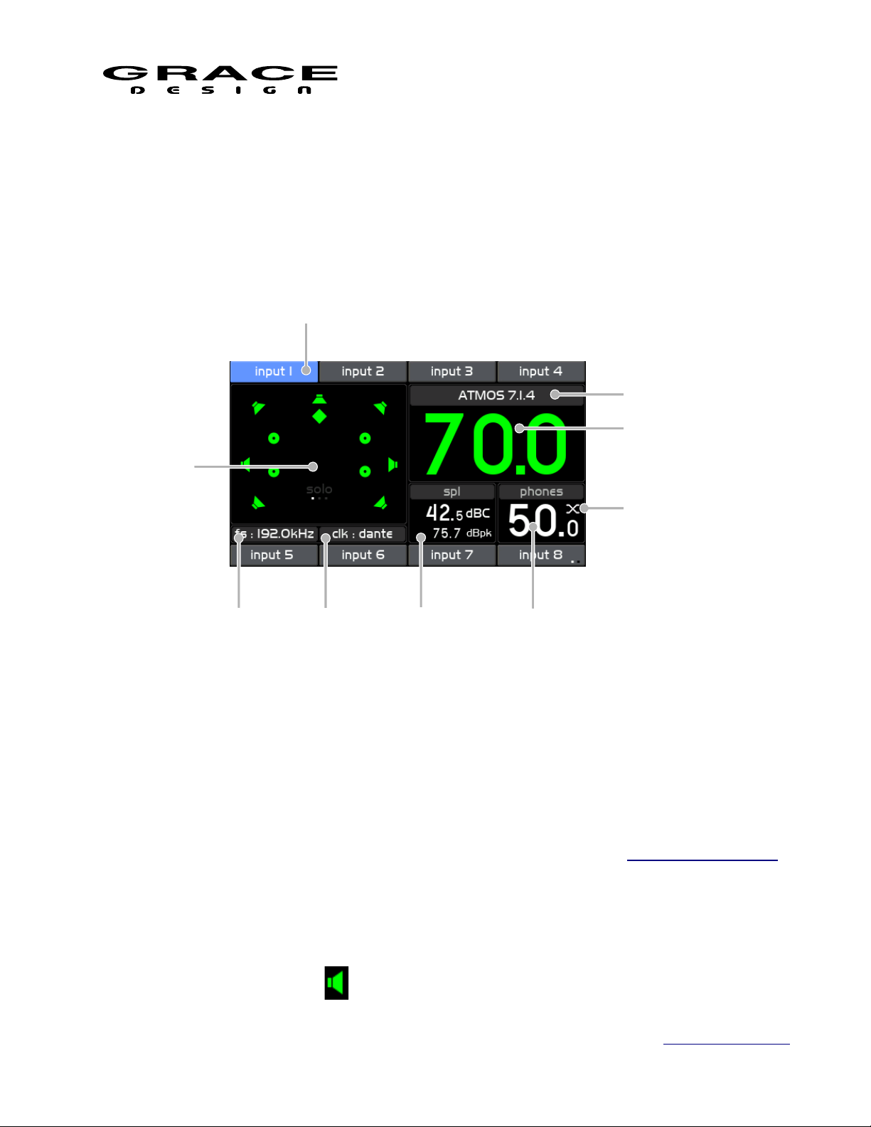
5.2 Home Screen
m908 Preliminary User Manual, Rev. 04
Illustration 9: Home Screen
The home screen provides an overview of the m908 system status.
5.2.1 1 Input Selection
The top and bottom bands of the LCD display area show the input sources available for
monitoring. The currently selected input will be highlighted in blue. With Input Summing Mode
active, the selected input(s) will be highlighted in green.
5.2.2 2 Control Room Speakers Layout Icons
Page 20 of 108 Table Of Contents
The Control Room speaker system layout window displays a graphic representation of the
currently selected speaker system. There are 4 types of speaker icons.
1. Front and Surround
Page 21

m908 Preliminary User Manual, Rev. 04
2. Top
3. SUB
4. Height
Each icon also acts as a signal level indicator. The level is monitored post-processing
and pre-volume control.
• White No signal present.
• Green Signal greater than -50dBFS
• Yellow Signal greater than -6dBFS
• Red Signal OVER
In the lower center area of the speaker system layout window is the solo/mute page and status.
The word "solo" will be visible in gray when the system is in solo mode. The word solo will be
visible in white when there is a speaker in solo mode.
The word "mute" will be visible in gray when the system is in mute mode. The word "mute"
will be visible in white when there is one or more speaker in mute mode.
The speaker system can be configured in the Speaker Output setup
5.2.3 3 Control Room Speaker Output
The name of the currently selected Control Room speaker system is displayed directly above
the Control Room Monitor Level.
5.2.4 4 Control Room Monitor Level
The current control room monitor level is displayed in large numbers which will be green
when the encoder is controlling the control room level. The default volume range is 0-100 in
0.5dB steps. 0 is mute and 100 is unity gain.
The Control Room Monitor Level can also be displayed with a user defined reference level.
This way the volume readout can be calibrated to SPL.
See Monitor Control setup for details on configuring the Control Room Monitor Level display.
5.2.5 5 Headphone Crossfeed
The Headphone Crossfeed circuit status is displayed in the upper right corner of the
headphones volume display window. See the X-FEED section of this manual for details.
5.2.6 6 Headphone Monitor Level
The current headphone monitor level is displayed in small numbers which will be green when
the encoder is controlling the headphone level.
See Monitor Control setup for details on configuring the Headphone Monitor Level display.
Page 21 of 108 Table Of Contents
Page 22
m908 Preliminary User Manual, Rev. 04
5.2.7 7 SPL Meter
Using the internal m908 RCU microphone, the m908 computes the real-time sound pressure
level based on the system configuration. The current and peak SPL levels are displayed along
with the filter mode in this section of the display. The peak spl value can be cleared at any time
with a push-hold of the MON>CUE (spl-clear) switch. The SPL measurement settings are
configured in SPL Meter setup.
When talkback is activated on the RCU, SPL monitoring will be suspended and the built in
microphone will switch to become the talback mic. The SPL Display area will indicate
TALKBACK ACTIVE. Upon exiting Talkback the SPL meter will return to normal operation.
5.2.8 8 Clock Source and Status
The clock status window displays the current clock source and indicates it's status by changing
the color of the text. See the Clocking section of this manual for details.
5.2.9 9 System Sample Rate
The sample rate display indicates the sample rate detected on the input connector. If the input
data or sample rate is invalid then the sample rate display will be blank (--).
5.3 INPUT SELECT
The m908 features a total of 16 input sources which are accessed with 8 dedicated INPUT
Select switches, in 2 rows of 4, above and below the LCD display. Each INPUT Select switch is
located adjacent to it's name area in the upper and lower bands of the display area. Pushing any of
these switches will select the associated input source and connect it to the monitoring path. When
an input is selected for monitoring it's name area background will be blue. Inactive inputs will
have a gray background in the name area.
The 16 inputs are displayed across two "pages" of 8 inputs. To switch between the input pages
push-hold the lower right INPUT select switch. The input name area next to the lower right hand
INPUT switch will show which page is currently being displayed with two small dots. When the
left dot is white inputs 1-8 are displayed. When the right dot is white inputs 9-16 are displayed.
Illustration 10: Input Page Select
Each input can be custom defined in the Setup Menu. The hardware connector, channel count,
level offset, sync delay, clock override mode, and name can be configured. See the Input Setup
Page 22 of 108 Table Of Contents
Page 23

m908 Preliminary User Manual, Rev. 04
section of this manual for details.
5.3.1 Input Summing Mode
The m908 allows up to three inputs to be summed. To enter summing mode, simultaneously
press the INPUT select switches for up to three of the desired inputs to sum. The inputs will
become active at the same time and the name areas will turn green on the display.
To change the inputs that are being summed press the INPUT select switches for the channels
that are to be removed from the sum then press the INPUT select switches for the channels that
are to be added to the sum.
Pressing any of the active INPUT select switches will toggle that input on and off in the sum.
To exit input summing mode simply de-select the inputs that you don't want in the sum. When
only one input is active push that switch and summing mode will turn off. The input name area
will be displayed in blue.
Any input that has clock override enabled can not be summed with other inputs.
Inputs that do not have identical Input sync delay settings can not be summed together. This is
because the delay happens after the input summing section in the m908.
Note: If the Meter Outputs are to provide metering for summed input signals the meter output
source must be set for <follow monitor post>.
5.4 DIM
The multi-function DIM / (x-feed) switch controls the monitor DIM and headphone x-feed
features.
Speaker DIM attenuates the current control room speaker system and/or the headphones by
the preset attenuation level. When dim is active, the switch is lit solid yellow.
DIM level and which outputs it affects can be configured in Dim setup.
5.5 X-FEED
Press-hold of the DIM / (x-feed) switch engages the Headphone cross-feed circuit in the
headphone output. When x-feed is active it is indicated on the headphone status display. X-feed
(cross-feed) simulates the acoustics of a loudspeaker listening environment which can
significantly improve imaging while reducing listening fatigue when using headphones. This
feature employs carefully designed signal cross-feed, filtering and delay circuits to simulate hrtf
(head related transfer functions).
Press-hold the DIM (x-feed) switch to toggle Headphone Crossfeed on and off. Crossfeed is
indicated in the upper right corner the phones volume window.
When listening to loudspeakers in a room, your left ear hears sound primarily from the left
speaker (and vice versa) but also receives a signal from the right speaker at a lower level and with
Page 23 of 108 Table Of Contents
Page 24

m908 Preliminary User Manual, Rev. 04
some time delay compared to the right ear. As well, the right speaker sound that reaches the left
ear does not have a flat frequency response as the sound waves have traveled around the shape of
your head before reaching your left ear. The brain uses delay, level and frequency response
characteristics to process the location of a sound and hence, create an aural image.
When listening to a stereo (or down-mixed) signal through headphones, each ear only hears
the sound from one transducer and the mixing of signals between the ears does not exist. In this
situation the brain is left without many of the psycho acoustic clues required to generate a
properly distributed image and an accurate sound stage. The result is that sounds seem to cluster
in the far left, far right or center of your head. Since the vital clues are absent, the brain has a
difficult time deciding how to process the sounds coming from the headphone, which can result
in listening fatigue when listening for extended periods of time. The m908 contains circuitry
which electronically simulates the signal cross-feed that occurs in a real acoustic space and helps
the brain establish instrument locations across the entire sound stage. While it is difficult to
perfectly model the very complex level, delay and frequency response characteristics of the head,
the cross-feed circuitry in the m908 gives the brain some of the basic clues it needs and the result
is a very pleasing simulation of an acoustic space. We chose the parameters of the cross-feed
circuit to find a good compromise between accurate imaging and tonal neutrality. For recreational
listening there could be more aggressive modeling of the head related transfer function (HRTF)
but this is usually at the expense of adding tone color. For critical monitoring during the
recording/editing/mixing process the user will find that the m908 cross-feed circuit provides a
sonically neutral character.
Below is a flow diagram and frequency response plot showing the response of the m908
crossfeed circuit. In this graph one channel of the headphone amplifier is driven. The two traces
show the direct channel and the opposite (cross-feed) channel.
Illustration 11: Headphone Crossfeed Flow Diagram
Page 24 of 108 Table Of Contents
Page 25
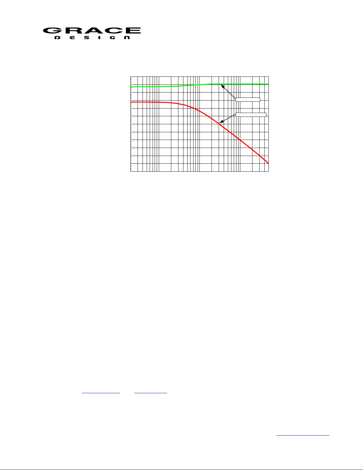
m908 Preliminary User Manual, Rev. 04
+5
+0
-5
-10
-15
-20
-25
dB
-30
-35
-40
-45
-50
-55
20 50k50 100 200 500 1k 2k 5k 10k 20k
Hz
DIRECT SIGNAL
CROSSFEED SIGNAL
Illustration 12: Headphone Crossfeed Response Plot
5.6 MONO / (L-R)
The multi-function MONO / (L-R) switch controls the MONO and the L-R (Left minus Right)
features.
Pressing the MONO causes the output of the m908 to play in mono.
When speaker / headphone MONO is active, the switch is lit solid yellow.
Press-hold of the MONO switch enters L-R mode. In this mode the m908 subtracts the right
channel from the left channel and provides this signal to the monitor output.
When L-R is active, the switch flashes yellow.
Press and release MONO witch:
• Toggles mono on and off. Disables L-R if currently active.
Push-hold switch:
• Toggles the L- R mode on and off. Disables MONO if currently active.
The MONO and L-R processing can be applied to the Control Room speakers and/or the
headphone outputs.
The signal source for the MONO and L-R processing can be the Left and Right channels of
whatever input is being monitored. The output of the MONO and L-R processing can be the Left
and Right speakers or the Center speaker.
See the MONO setup and (L-R) setup for configuration options.
5.7 MON>CUE
Page 25 of 108 Table Of Contents
Page 26

m908 Preliminary User Manual, Rev. 04
The MON>CUE switch activates Monitor to Cue mode which routes the currently selected
monitor source to the CUE outputs. The MON>CUE function can be enabled or disabled for each
of the cue outputs. Also, the send to the cue outputs can be the Left and Right channels of the
current monitor source or a stereo downmix if the source is in surround.
When active the MON>CUE switch will illuminate green.
See the CUE setup for configuration options.
5.8 MUTE
The MUTE switch mutes the audio in the control room speaker and/or the headphones. When
active the MUTE switch will illuminate red.
See the MUTE setup for configuration options.
5.9 CR1, CR2, CR3
Speaker system selection is made with one of the three CR (Control Room) switches.
Each output is defined in the Setup Menu. The hardware connector, channel count, level
offset, delay, bass management parameters, room correction eq, and name can be configured in
the CR Setup section of this manual.
The control room speaker select switches are exclusive and only one can be selected at a time.
The currently selected speaker switch will illuminate green.
5.10 BASS MANAGEMENT
The m908 includes comprehensive Bass Management control. Each speaker in the Control
Room system can be individually configured for crossover frequency, high pass filter slope, and
low pass filter slope. The internal summing of the LPF signals is done in stereo. All left channel
speakers are added to the Left sub bus, right channel speakers are added to the Right sub bus, and
center speakers are added to both busses equally. The user can decide to use stereo sub woofers
or use a mono sum of the stereo bus.
The high pass filter can be bypasses to a full range signal is sent to the speaker. As well, the
low pass filter can be turned off so that no signal is sent to the sub woofers.
See the Bass Management setup section of this manual for details.
The LFE input channel contains a variable low pass filter and a 0 or +10dB gain setting. These
are system level settings which are contained in the Monitor Control setup. See the Monitor
Control setup section of this manual for details.
Page 26 of 108 Table Of Contents
Page 27
m908 Preliminary User Manual, Rev. 04
IN 2,3...
IN 1
OFF
20-150Hz HPF
20-150Hz LPF
50-150Hz HPF
6,12,18,24dB/oct
50-150Hz LPF
6,12,18,24dB/oct
OUT 2, 3...
WORKFLOW
DEPENDENT
OFF
OUT 1
WORKFLOW
DEPENDENT
OFF
SUB MODE
IN LFE
80-120Hz LPF
0dB
+10dB
Σ
Σ
SUB OUT L
SUB OUT C
SUB OUT R
Σ
SUB MODE
Illustration 13: Bass Management Flow Diagram
5.11 ROOM CORRECTION
The Control Room speaker output channels each contain up to 6 fully parametric bands of
Page 27 of 108 Table Of Contents
Page 28

m908 Preliminary User Manual, Rev. 04
equalization for correcting minor frequency response aberrations in your control room.
The first 7.1, 7.2 or 7.3 channels in a speaker system will have 6 bands of eq per speaker. The
remaining speaker channels (if any) have 3 bands.
Each band of eq can be set for high pass, low pass, high shelf, low shelf, and peak response.
See the Room Correction setup section of this manual for details.
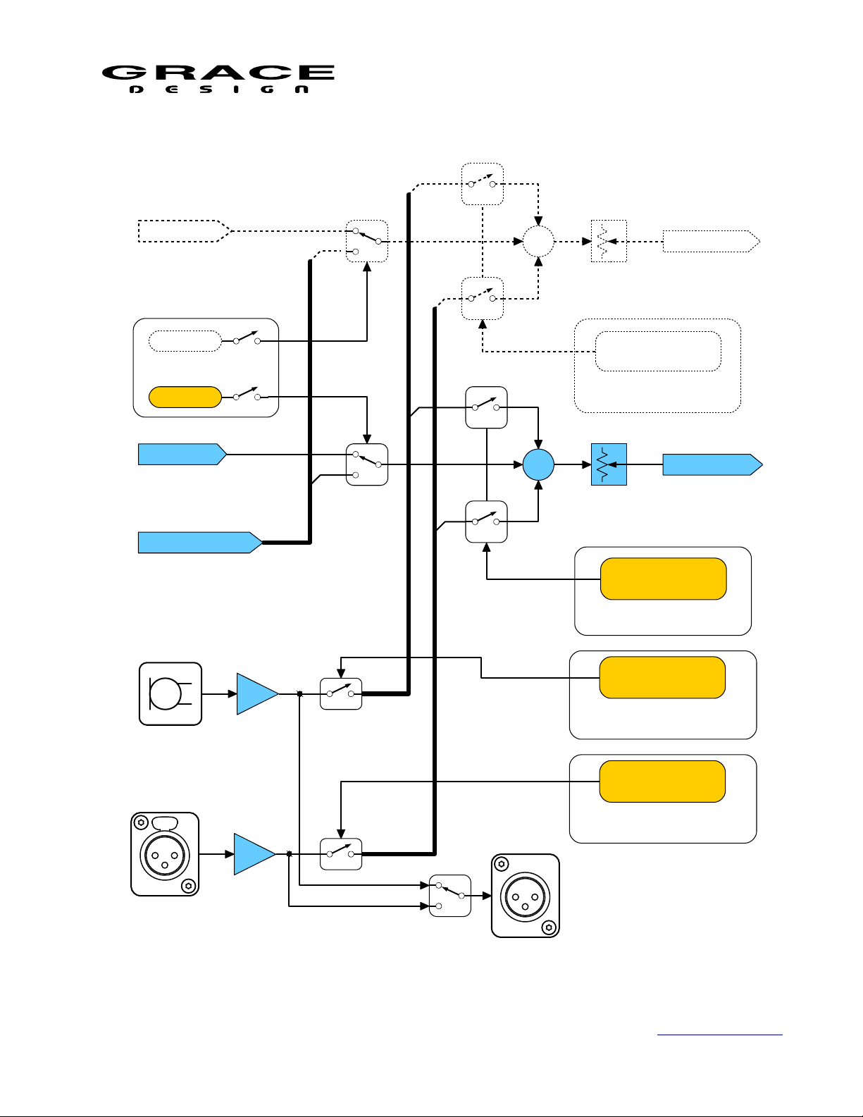
5.12 TALKBACK
The m908 has a flexible talkback system that can be adapted to a wide range of applications.
There is a microphone built in to the RCU and a talkback mic amp built in to the ACU. The
talkback microphones can be controlled from multiple trigger sources and routed to multiple
CUE paths. Trigger sources include the RCU TALKBACK switch, an external talkback switch
jack on the ACU, A B and C User switches, and GPIO input pins. As well, GPIO pins can be
programmed to output a logic level tally when talkback is active. Multiple routing configurations
allow different talkback triggers to route talkback audio to various CUE sends. For instance, you
can have the main TALKBACK switch on the RCU send talkback audio to all cue sends while
USER A switch can send talkback audio to only a specific CUE output.
The analog XLR Talkback Output jack on the ACU outputs the talkback signal from the
currently active talkback mic. This allows the Talkback signal to be sent to other headphone
systems or studio playback speakers.
Page 28 of 108 Table Of Contents
Page 29
m908 Preliminary User Manual, Rev. 04
CUE INPUT 1
CUE OUTPUT 1
CUE INPUT 2
CUE OUTPUT 2
RCU TALKBACK MIC
ACU TALKBACK MIC AMP
MON>CUE
MON>CUE
CR MONITOR INPUT
Σ
MON>CUE
CUE ASSIGN
TALKBACK SWITCH
CUE ASSIGN
TALKBACK SWITCH:
RCU, EXT, A-B-C,OR
GPIO
RCU TALKBACK MIC
SWITCH ASSIGN
TALKBACK SWITCH:
RCU, EXT, A-B-C,OR
GPIO
ACU TALKBACK MIC
SWITCH ASSIGN
TALKBACK SWITCH:
RCU, EXT, A-B-C,OR
GPIO
TALKBACK SWITCH
CUE ASSIGN
TALKBACK SWITCH:
RCU, EXT, A-B-C,OR
GPIO
Σ
ACU TALKBACK OUT
Illustration 14: Talkback-Cue Flow Diagram
Page 29 of 108 Table Of Contents
Page 30

m908 Preliminary User Manual, Rev. 04
The TALKBACK, ABC, and external talkback switches use an automatic latch/momentary
operation. A quick press-release will latch the talback mic on. Press-release again to turn talkback
off. Pushing and holding the talkback switch will activate talkback only while the switch is being
held down (momentary mode).
Pressing and releasing these switches quickly latches the talkback function on or off. Pushhold of the TALKBACK switch operates the talkback function for as long as the switch is held
down.
See the Talkback setup section of this manual for configuration details
5.13 SOLO/MUTE
The nine bi-colored SOLO/MUTE switches are used to solo or mute any individual channel or
group of channels being monitored. Eight of the switches engage solo or mute for the relevant
channel, while the solo/mute switch is used to toggle between solo or mute mode.
When in Solo mode the SOLO/MUTE switch will illuminate green. Pressing any of the 8
SOLO/MUTE switches will toggle solo mode on and off for that channel. In the speaker layout
window the word "solo" will appear in green and channels that are not soloed will be grayed out.
When in Mute mode the SOLO/MUTE switch will illuminate red. Pushing and of the 8
SOLO/MUTE switches will toggle mute mode on and off for that channel. In the speaker layout
window the word "mute" will appear in red and channels that are muted will be grayed out.
The SOLO/MUTE switches handle a complete 7.1 speaker system. However, if your speaker
system has more than 8 channels the SOLO/MUTE switches can "page" to the higher order
channels.
To page to higher order channels push-hold the RB switch. To page to lower order channels
push-hold the LB swich. The current solo/mute page is indicated in the group of 3 small dots in
the middle area of the speaker layout section of the LCD display. The current solo or mute mode
is indicated right above the page dots.
Page 30 of 108 Table Of Contents
Page 31

m908 Preliminary User Manual, Rev. 04
L C R
RSLS
SUB
RBSOLO/MUTELB
PAGE
INDICATORS
PUSH HOLD
PAGE LEFT
PUSH HOLD
PAGE RIGHT
Illustration 15: Solo/Mute Page Keys
With the three "pages" of SOLO/MUTE switches there are a total of 24 controls. From the
factory the first 8 of the SOLO/MUTE switches are mapped to speaker channels as indicated on
the RCU panel: L, C, R, LS, SUB, RS, LB, RB. SOLO/MUTE switches 9-16 are unassigned.
More than one speaker channel can be mapped to a SOLO/MUTE switch. This allows for
solo/mute "groups" to be created. For instance, you could have a SOLO/MUTE switch assigned
to all of the overhead speakers in an ATMOS system. One button press would then allow muting
and soloing of the whole group of speakers at once.
The mapping of speaker channels to SOLO/MUTE switches can be changed in the SOLO
MUTE Setup section of this manual.
5.14 VOLUME (push for phones)
The m908 utilizes a single rotary push-button encoder for the control room speaker volume
level, headphone volume level, and volume level preset recall.
Pushing the VOLUME encoder toggles between Control Room and Headphone control.
Turning the VOLUME encoder increases and decreases the monitoring level in 0.5dB steps.
The volume control is speed sensitive, so the turning the knob at a higher velocity results in faster
volume changes with larger step sizes.
With Control Room Speaker control active:
Push-hold of the VOLUME encoder will set the monitoring level to the Preset Level.
There are two modes of level display for the Control Room level:
• Standard Mode The Control Room level range is 0-100 with 0 being mute and 100 being
unity gain. With 0.5dB steps this is a 99.5dB attenuation range.
• Reference Mode The control room level readout can be scaled so that a calibrated
Page 31 of 108 Table Of Contents
Page 32

m908 Preliminary User Manual, Rev. 04
monitoring level can be displayed as 0dB.
With Headphone control active:
Push-hold of the VOLUME encoder will set the monitoring level to the Preset Level.
See the Monitor Control setup section of this manual for configuration details.
5.15 A B C User Switches
The ABC User Switches are software definable and can be configured to control a variety of
system commands.
Available uses are pre-defined monitoring modes called "Monitor Snapshots", additional
talkback triggers, and GPIO triggers.
See the A B C User Switches Setup and Monitor Snapshot setup section of this manual for
configuration details.
When configured for Talkback the User switches will behave just like the dedicated Talkback
switch and will illuminate RED when active.
When configured for Monitor Snapshot the User switches will recall the prescribed Monitor
Snapshot settings and illuminate GREEN.
When configured to be GPIO triggers the User switches will toggle on and off and illuminate
GREEN when active.
5.16 Monitor Snapshots
Monitor Snapshots are presets that contain a set of monitoring settings that can be recalled
quickly. The Monitor Snapshots are assigned to A, B, or C User switches for easy access.
Snapshots are "captured" from the current m908 monitoring settings. Up to 3 snapshots can be
stored and assigned to the User A,B, and C switches.
The following settings can be selected to be stored in a Monitor Snapshot:
• input source
• downmix
• control room speaker selection
• control room speaker volume
• headphone volume
• mono
• dim
• solo/mute
See the Monitor Snapshot setup section of this manual for details on selecting monitor
functions to be included.
Once the monitoring settings have been selected do the following to "capture" a Snaphot.
• Set the m908 to the desired monitoring state.
Page 32 of 108 Table Of Contents
Page 33

m908 Preliminary User Manual, Rev. 04
• Push long-hold the corresponding User A, B, or C switch until it illuminates green.
If downmix was enabled in setup then the selected downmix template will be activated and
the display will indicate the downmix being used in the speaker layout area.
Illustration 16: Home Screen with Downmix Active
Pushing the User witch again will turn off downmix and turn of the green illumination but all
the other monitoring settings will stay the same.
Otherwise, the switch will remain illuminated green until any setting is changed that makes
the current monitor state not match the state stored in the snapshot. When this happens the switch
will blip green. Pushing the switch will turn off the Monitoring Snapshot and the switch LED
will extinguish. Pushing the switch again will recall the stored Monitor Snapshot.
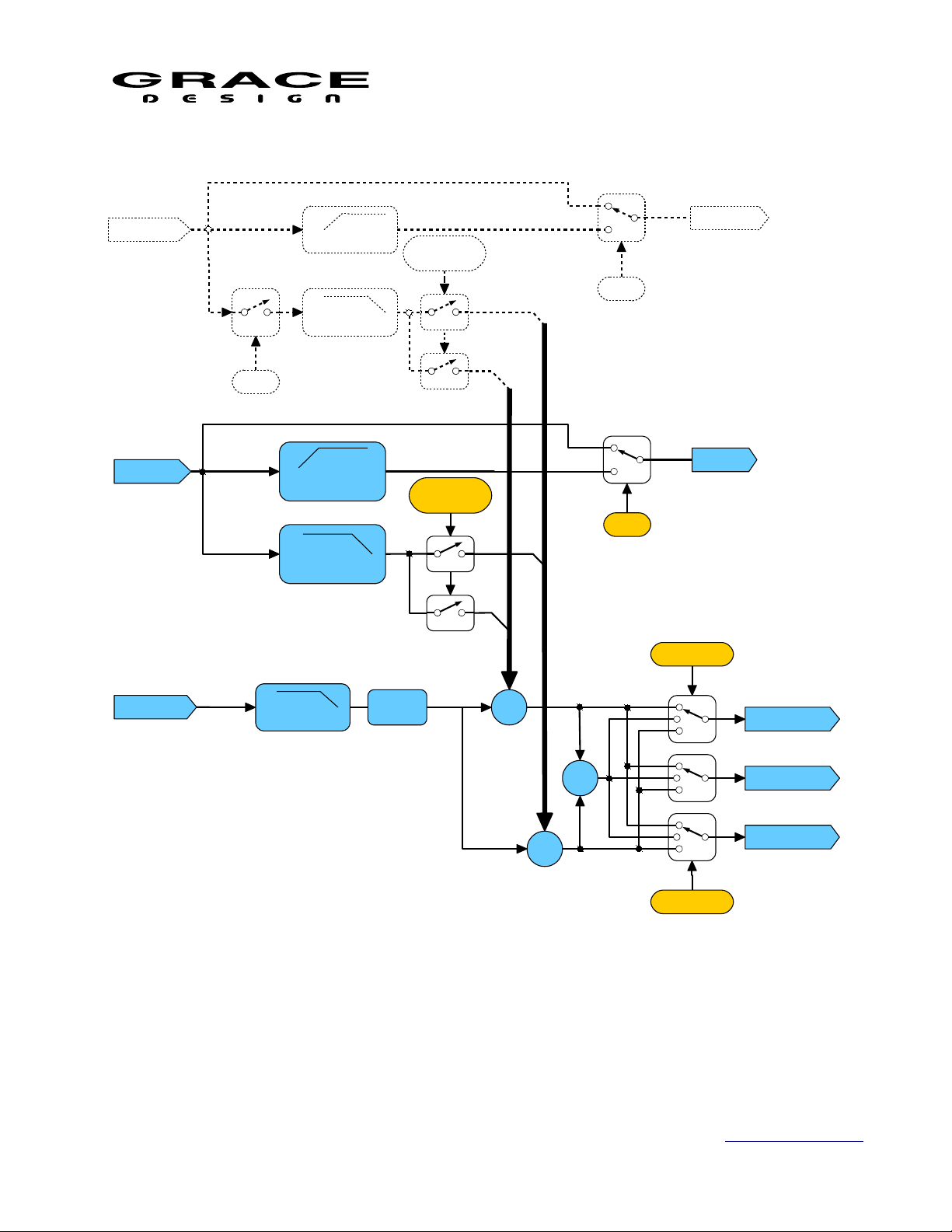
5.17 Meter Outputs
The m908 allows for flexible routing of input signals to Meter Outputs.
AUDIO INPUTS
DIGITAL INPUTS
ANALOG INPUTS
MONITOR
SOURCE SELECT
LEVEL
OFFSET
DSP
AUDIO OUTPUTS
DIGITAL OUTPUTS
ANALOG OUTPUTS
METER
INPUT SELECT
METER OUTPUTS
Page 33 of 108 Table Of Contents
Illustration 17: Meter Signal Flow Diagram
Page 34

m908 Preliminary User Manual, Rev. 04
The meter source options are:
• Audio Input source
This option fixes the Meter source to a specific input. The signal level is identical to the
incoming signal level.
• Follow monitoring source selector pre level offset
This option allows the Meter source to follow whatever is being monitored on the Control
Room speakers. The signal level is identical to the incoming signal level.
• Follow monitoring source selector post level offset
This option allows the Meter source to follow whatever is being monitored on the Control
Room speakers. The signal level follows whatever input level offset is set for the
currently selected input.
The Meter outputs can be assigned to any hardware output connector that is not being used by
a Control Room speaker or a Cue output.
Note: CR1, CR2, and CR3 OUT can not be used for meter outputs.
See the Meter Output setup section of this manual for details on Meter Output routing.
5.18 **Downmix
The m908 contains a predefined set of downmix mixers. Each mixer contains downmix level
parameters. These parameters are set to default Dolby metadata values in most cases. Downmix
templates are accessed by adding a template to a Monitoring Snapshot. See the Monitor Snapshot
setup section of this manual for configuration details.
Downmix formulas
• 7.1 > 5.1 PLII (Pro Logic II)
◦ LMS = LMS + (–1.2dB x LBS) + (–6.2dB x RBS)
◦ RMS = RMS + (–6.2dB x LBS) + (–1.2dB x RBS)
• 7.1 > 5.1
◦ LMS = 0 dB x LMS + 0 dB x LBS
◦ RMS = 0 dB x RMS + 0 dB x RBS
• 7.1 > Lt/Rt
◦ Lt = L + (–3 dB x C) – (–3 dB x (LMS + LBS)) – (–3 dB x (RMS + RBS))
◦ Rt = R + (–3 dB x C) + (–3 dB x (LMS + RBS)) + (–3 dB x (RMS + RBS))
• 7.1 > Lt/Rt PLII (Pro Logic II)**
◦ Lt = L + (–3 dB x C) – (–3 dB x (LMS + (–1.2dB x LBS) + (–6.2dB x RBS))) – (–3
dB x (RMS + RBS))
◦ Rt = R + (–3 dB x C) + (–3 dB x (RBS + (–6.2dB x LBS) + (–1.2dB x RBS))) + (–3
Page 34 of 108 Table Of Contents
Page 35

m908 Preliminary User Manual, Rev. 04
dB x (RMS + RBS))
• 5.1 to Lt/Rt:
◦ Lt = L + (–3 dB x C) – (–3 dB x LMS) – (–3 dB x RMS)
◦ Rt = R + (–3 dB x C) + (–3 dB x LMS) + (–3 dB x RMS)
• 5.1 to Lt/Rt (Pro Logic II)
◦ Lt = L + (–3 dB x C) – (–1.2 dB x LMS) – (–6.2 dB x RMS)
◦ Rt = R + (–3 dB x C) + (–6.2 dB x LMS) + (–1.2 dB x RMS)
• 5.1 to Lo/Ro
◦ Lo = L + (–3 dB x C) + (–3 dB x LMS)
◦ Ro = R + (–3 dB x C) + (–3 dB x RMS)
•
To enable a downmix mixer one of the A, B, or C User switches must be assigned to Monitor
Snapshot mode with a downmix template selected. See the A B C User Switches Setup section of
this manual for details.
Up to three downmix templates can be used by assigning each A, B, and C switches to a
Monitor Snapshot.
For Downmix to work properly the Input Source and the Control Room output speaker system
must match the input and output channel configuration of the selected Downmix template. For
instance, if a 7.1 downmix template is enabled, the Input source should be 7.1 and the Control
Room output speakers should have at least as many channels as the downmix output.
A downmix template can be included in a Monitoring Snapshot which makes it easy to define
an Input, Control Room output, and a downmix template with a single switch push. See the
Monitor Snapshot section of this manual for details.
See the Downmix setup section of this manual for configurations details.
5.19 Clocking
The m908 System Clock can run from an internal crystal reference or it can lock to external
Word Clock or digital audio input. See Clock Source Setup for configuration details.
The m908 will attempt to lock to the clock source selected in System setup. If the selected
clock is at a valid sample rate (see Electrical Specifications for frequency ranges) the m908 will
lock and the Clock Display will indicate the lock status.
If the System Clock is present but not at a valid sample rate the m908 will attempt to lock to
the audio data source and play audio.
Page 35 of 108 Table Of Contents
Page 36

Clock Status
m908 Preliminary User Manual, Rev. 04
Clock Status
Display
White Locked to System Clock
Yellow Locked to System Clock
Flashing Red Unlocked. No clock
Flashing Red Locked. Not at same
If the input source is composed of more than one hardware input source (4 AES3 signals for
instance) the m908 will lock to the lowest channel number.
The m908 does not contain a sample rate converter. If the clock source is set to a source that is
not the same as the audio data source then it is assumed that the audio data will be at the same
sample rate and be synchronous to the clock source.
If the m908 system clock source is set to one of the Internal sample rates then the m908 is the
clock master. Any digital audio source connected to the m908 will need to be synchronized to the
m908 word clock output.
System Clock Status Audio Source Condition
Audio data and sample rate valid
source
source
present or out of range
sample rate as audio
m908 will play audio.
Input source set for Clock Override.
m908 will play audio at incoming data sample rate.
Audio data valid
m908 will play audio at incoming data sample rate.
Audio data valid.
m908 will play audio at incoming data sample rate.
If there is a digital input source that can not be synchronized to an external clock (CD player
for instance) then set the override clock in the Input Setup for that device. When that input is
selected for monitoring, the System Clock will switch the clock source to that input audio stream
automatically. See the Input Setup section of this manual for details.
5.20 Word Clock In and Out
The m908 can accept a standard 5V/75Ω word clock signal from an external clock generating
unit. This might be a stand-alone master clock source or the word clock output from your digital
audio workstation interface. The m908 locks to the incoming word clock with an ultra low jitter
s-Lock PLL. The PLL has a fast lock mode which rapidly acquires lock and then switches to a
high jitter rejections mode with a loop bandwidth of 0.5Hz. This provides exceptional jitter
rejection for the ADC and DAC sample clocks. In the event of a dropout or loss of incoming
word clock signal, the intelligent PLL will remain at the last known valid frequency. When the
signal is restored the PLL will smoothly re-acquire lock.
The word clock output allows the user to synchronize other digital audio equipment to the
m908. When the menu setting clock output is set to <clock in> this connector output is a copy of
the signal on the Word Clock IN jack. This mode is useful for "daisy chaining" multiple devices
together in a system. When clock output is set to <system clock> this connector outputs a copy
Page 36 of 108 Table Of Contents
Page 37

m908 Preliminary User Manual, Rev. 04
WC IN
WC OUT
75Ω
CLOCK TERM CLOCK OUT
s-LOCK
PLL
of the m908 system word clock. The Word Clock output jack is buffered and is designed to drive
a 75Ω line at 5V.
Illustration 18: Word Clock Flow Diagram
If the clock output parameter is set for <system clock> and the m908 is being synchronized to
an external word clock, the Word Clock output will be a re-clocked low jitter version of the
incoming clock. If the incoming clock is interrupted the m908 will continue to transmit on the
Word Clock output at the last frequency that the system was locked to. When the input clock is
restored the m908 will re-lock smoothly unless then new incoming sample rate has changed.
See Word Clock Termination Setup and Word Clock Output Setup for setup instructions.
5.21 Error Messages
The ACU monitors several hardware systems for fault conditions and will report errors if there
are any detected faults.
5.21.1 ACU Over Temperature
The ACU contains a temperature sensor on the circuit board near the main DSP processor. If
the temperature rises above a safe level for the processor then the RCU will report an over
temperature condition.
If this message appears check that the ACU has proper ventilation and that the ambient
temperature where it is installed is below 40°C (104°F). Verify that the fan exhaust on the right
side of the chassis and the cool air inlet openings on the left side of the chassis are not obstructed.
Page 37 of 108 Table Of Contents
Page 38

m908 Preliminary User Manual, Rev. 04
Illustration 19: ACU Temperature Error
5.21.2 PSU Error
The PSU contains a processor that monitors the voltages from the two redundant power supply
modules. If any of these voltages fall outside of the permitted tolerance then this will be
communicated to the ACU and a warning will appear on the RCU display screen. If this error
occurs contact Grace Design Technical Support
Illustration 20: PSU Error
5.21.3 Communication Error
The RCU and ACU communicate over a balanced RS485 serial link. If the RCU experiences a
communication error this screen will be displayed.
Page 38 of 108 Table Of Contents
Page 39

m908 Preliminary User Manual, Rev. 04
Illustration 21: Communication Error
5.21.4 Cooling Fan Error
The m908 conatins a cooling fan that will turn on if the internal temperature of the m908 rises
above a preset level. At power up the ACU processor tests the fan to ensure that it is runs at the
proper rpm. If the fan fails to rotate at the proper rpm this error message is shown.
Illustration 22: Cooling Fan Error
6 System Setup
6.1 Introduction
There are two setup menus for the m908: Workflow Setup, and System Setup. Workflows are
system presets that determine the mode that the DSP section of the m908 will operate in.
Workflow Setup allocates the 24 DSP channels for the speaker system, cue system, stereo
headphone monitor, and talkback system. Speaker system formats range from Stereo to 24
Page 39 of 108 Table Of Contents
Page 40

m908 Preliminary User Manual, Rev. 04
INPUT
CONFIG
AND ROUTING
DSP
CONFIG
OUTPUT
CONFIG
AND ROUTING
WORKFLOW
SETUP
SETUP SETUP
CLOCK
GPIO
TALKBACK
BACKLIGHT
ABC SWITCHES
SETUP
channel monitoring. When choosing a speaker system format that uses less than 24 channels, the
remaining processor channels can be assigned as cue channels, stereo headphone monitor, and
talkback.
For instance, if you select a 7.1 Workflow, 8 channels of the processor will be allocated to
speaker processing, while the remaining 16 channels can be allocated to 4 stereo Cue channels,
stereo headphones, and two talkback mics.
Note that the number of channels assigned to the speaker system represents the maximum
number of speakers that can be used. However, the m908 supports multiple speaker systems so,
for instance, with the example above you could have a 7.1, 5.1 and stereo speaker system
connected to the m908.
In the System Setup menu the input sources and speaker outputs can be configured. Input
sources can be assigned to hardware connectors and routed to the appropriate DSP channels.
Speaker systems can be assigned to hardware output connectors and routed from the appropriate
DSP channels.
Illustration 23: Workflow Setup Flowchart
The m908 contains a large set of workflow templates for the most common speaker system
formats and typical input and output configurations. Selecting one of these templates as a starting
point for your system setup can save much time and effort in manual configuration.
System Workflows contain ALL of the configuration settings in the m908. System Workflows
Page 40 of 108 Table Of Contents
Page 41

m908 Preliminary User Manual, Rev. 04
can be saved to a USB storage device for making a backup of the system settings. This also
makes it easy to load a specific setup in to multiple m908s.
6.2 Workow Setup
The m908 ships from the factory with one workflow installed. This workflow is called
ATMOS 7.1.4. If this matches your speaker system requirements then you can skip Workflow
Setup and continue to the System Setup section of this manual. If you want to load a new
Workflow from a factory template or modify the existing workflow then continue with Workflow
Setup.
NOTE: Changes made to the current workflow are not updated in real time. If changes are
made they will not become active until the workflow is saved.
6.2.1 Workow Setup Main Screen
To setup the system workflow push long-hold the SETUP switch (for 3 seconds). The SETUP
switch will start flashing quickly and the display will have red colored bars across the top and
bottom of the screen. When in workflow setup, monitor control functions are held in their current
state and cannot be changed until workflow setup is exited.
The top bar displays the message: CHANGES WILL RECONFIGURE SYSTEM
The bottom bar displays: SYSTEM WORKFLOW: <CURRENT WORKFLOW>
Illustration 24: Main Workflow Setup Screen
The Workflow Setup screen is divided in to two main windows. In the left window is a graphic
representation of speaker system. At the bottom, there are indicators showing the number of
stereo cue channels, talkback mics, and headphone system status. In the middle of this window is
an indicator displaying the DSP channel utilization for the active workflow.
The right window contains a menu list with the following options:
1. <edit> Edit a workflow
2. <load> Load an existing workflow
Page 41 of 108 Table Of Contents
Page 42

m908 Preliminary User Manual, Rev. 04
3. <copy> Copy an existing workflow to a new workflow
4. <new> Create a new workflow from a list of factory workflow templates
5. <import from usb> Import a workflow from a file saved on a USB storage device
6. <export to usb> Save a workflow to a USB storage device
7. <delete> Delete a workflow
Use the VOLUME knob to scroll up and down the list. Push the VOLUME knob to select a
menu item.
6.2.2 Select Workow To Edit Screen
Illustration 25: Select Workflow to Edit Screen
Selecting <edit> from the main workflow setup screen enters this screen.
The Select Workflow To Edit Screen screen is divided in to two main windows.
In the right hand window there is a list of all of the available user workflows. If this is a new
m908 there will be only one workflow listed (ATMOS 7.1.4) The currently loaded workflow will
be highlighted in the list. At the top of the list is the <exit> menu option.
In the left window is a graphic representation of all of the assigned speaker locations for the
workflow that is highlighted in the list to the right. At the bottom are three small windows that
indicate the following status for the currently highlighted workflow:
1. cues:1-8
2. tb:1-2
3. phones:on-off
To edit a workflow: scroll to the desired workflow and push the VOLUME encoder. This will
open the selected workflow for editing.
To exit the workflow edit window: scroll to <exit> and push the VOLUME encoder.
Page 42 of 108 Table Of Contents
Page 43

m908 Preliminary User Manual, Rev. 04
6.2.3 Editing Workow Screen
Illustration 26: Editing Workflow Screen
In the right window the following menu items are:
1. <cancel> Returns to the previous screen. Asks if you want to exit without saving.
2. <save and exit> Saves the changes to the edited workflow and returns to the previous
screen. Asks if you want to save your changes.
3. <rename> Opens the workflow name editing screen with keyboard.
4. <channel setup> Enters channel setup mode where speakers, cues, talkback mics and
headphones can be added or subtracted from the workflow.
In the left window all of the available speaker positions will be visible. If a speaker position is
enabled for the current workflow it will be white. If it is not enabled it will be gray. At the bottom
of this window the number stereo cues, talkback mics, and headphone status is displayed.
Page 43 of 108 Table Of Contents
Page 44

m908 Preliminary User Manual, Rev. 04
Speaker Names
FRONTS HEIGHT FRONT TOPS
LEFT LEFT HT LEFT FRONT 1 TOP
LEFT CENTER LEFT SCREEN HT RIGHT FRONT 1 TOP
LEFT SCREEN LEFT CENTER HT LEFT FRONT 2 TOP
CENTER CENTER HT RIGHT FRONT 2 TOP
RIGHT SCREEN RIGHT CENTER HT LEFT MIDDLE TOP
RIGHT CENTER RIGHT SCREEN HT CENTER MIDDLE TOP
RIGHT RIGHT HT RIGHT MIDDLE TOP
LEFT BACK 1 TOP
SIDE SURROUNDS HEIGHT SURROUND RIGHT BACK 1 TOP
LEFT WIDE LEFT WIDE HT SURR LEFT BACK 2 TOP
RIGHT WIDE RIGHT WIDE HT SURR RIGHT BACK 2 TOP
LEFT FRONT SURR LEFT FRONT HT SURR
RIGHT FRONT SURR RIGHT FRONT HT SURR SUBS
LEFT MIDDLE SURR LEFT MID HT SURR LEFT SUB
RIGHT MIDDLE SURR RIGHT MID HT SURR CENTER SUB
LEFT BACK SURR LEFT BACK HT SURR RIGHT SUB
RIGHT BACK SURR RIGHT BACK HT SURR
BACKS HEIGHT BACK
LEFT BACK LEFT HT BACK
LEFT CENTER BACK LEFT CENTER HT BACK
CENTER BACK CENTER HT BACK
RIGHT CENTER BACK RIGHT CENTER HT BACK
RIGHT BACK RIGHT HT BACK
6.2.4 Workow Channel Setup Screen
Scroll to the <channel setup> menu option and push the VOLUME encoder to enter the
channel setup screen.
Page 44 of 108 Table Of Contents
Page 45

m908 Preliminary User Manual, Rev. 04
Illustration 27: Workflow Channel Setup Screen
In the channel setup screen the VOLUME encoder controls a highlight cursor that can be
moved from speaker to speaker through all of the possible speaker positions. When a speaker is
highlighted push the VOLUME encoder to enable/disable that speaker position. When the
speaker is enabled it will be white. When the speaker is disabled it will be gray. The name of the
currently selected speaker will be shown in the right hand window.
The small window in the middle of the speaker icons shows the current tally of DSP channel
utilization. It will update with the number of DSP channels allocated as you add or subtract
speakers. Continue scrolling through all of the speakers to get to the cue, talkback, and
headphones setup. When one of these switches is highlighted pushing the VOLUME encoder will
toggle through the following options:
• cues: Each push of the encoder increases the number of stereo cue paths to a maximum
of 8 stereo cues. The number of cue channels is limited by the available DSP channels.
For example, if there are only 4 DSP channels available then pushing the VOLUME
encoder will toggle through cues:0, cues:1, and cues:2.
• tb: Each push of the VOLUME encoder increases the number of talkback channels
to a maximum of 2. The number of talkback channels is limited by the available DSP
channels.
• phones: Each push of the VOLUME encoder toggles the headphone system on or off.
The headphone outputs require 2 available DSP channels.
To exit the channel setup screen, push-hold the VOLUME encoder.
6.2.5 Editing Workow Rename Screen
From the Editing Workflow screen clicking the <rename> menu option will open the
Workflow Rename Screen. This uses Standard Name Editing interface. If a name is chosen that is
already used by another existing workflow the system will not overwrite the existing workflow. A
Page 45 of 108 Table Of Contents
Page 46

m908 Preliminary User Manual, Rev. 04
dialog box will appear indicating the conflict.
Illustration 28: Editing Workflow Rename Conflict
Clicking OK in this dialog will return to the Workflow name editing screen so that another
name can be entered.
To cancel Workflow Rename select the CANCEL button on the rename keyboard.
6.2.6 Editing Workow Save and Exit
From the Editing Workflow screen clicking the <save and exit> menu option will open a
dialog box asking if you are sure you want to save changes made to the workflow open for
editing. This dialog appears whether or not any changes were made.
Illustration 29: Save System Workflow Changes Dialog
If the workflow being edited is the currently active system workflow the changes will be
executed upon exiting. All monitor levels will be set to zero.
Page 46 of 108 Table Of Contents
Page 47

m908 Preliminary User Manual, Rev. 04
Illustration 30: Save Active System Workflow Changes
Dialog
Exiting from the editing workflow screen returns to the main workflow setup screen. To exit
this screen and return to the home screen press the flashing SETUP switch.
Note that if any changes have been made to the workflow that affect the number of speakers,
their positions, number of cue channels, talkback mics, or headphone status then there will need
to be routing changes made in the regular setup menus to reconnect hardware inputs and outputs
to the changed DSP channels.
If changes were made to a workflow that is not the currently loaded system workflow then that
workflow would need to be loaded so that routing changes can be made.
Changes to the workflow name will not have any effect on routing.
6.2.7 Editing Workow Cancel
From the Editing Workflow screen clicking the <cancel> menu option will open a dialog box
asking if you are sure you want to discard changes.
Page 47 of 108 Table Of Contents
Page 48

m908 Preliminary User Manual, Rev. 04
Illustration 31: Cancel System Workflow Changes
Dialog
Selecting "NO" will return to the workflow editing screen.
Selecting "YES" will exit to the main workflow setup screen.
To return to the home screen press-release the flashing SETUP switch.
6.2.8 Workow Load
Illustration 32: Selected Workflow to Load Screen
The Select Workflow To Load screen displays a list of the Workflow presets that have been
saved on the m908. While scrolling through the list of workflows the DSP channel allocations
will be displayed on the left window. Push the VOLUME encoder to select a workflow. A
confirmation dialog box will appear asking if you want to load the selected preset.
Page 48 of 108 Table Of Contents
Page 49

m908 Preliminary User Manual, Rev. 04
Illustration 33: Load System Workflow Dialog
Select YES to load the workflow in to the m908. The system will be updated. Select NO to go
back to the Select Workflow To Load screen.
If YES is selected the system will be reconfigured to the new workflow and all monitor levels
will be set to zero.
Select <exit> to exit the Select Workflow To Load screen without loading a new workflow.
6.2.9 Workow Copy
Illustration 34: Select Workflow to Copy Screen
The Select Workflow To Copy screen displays a list of the Workflow presets that have been
saved on the m908. While scrolling through the list of workflows the DSP channel allocations
will be displayed on the left window. Push the VOLUME encoder to select a workflow. A
confirmation dialog box will appear asking if you want to copy the selected preset.
Page 49 of 108 Table Of Contents
Page 50

m908 Preliminary User Manual, Rev. 04
Select YES to copy the workflow. The list of workflows will now include the new copy.
Select NO to go back to the Select Workflow To Copy screen.
The new copy will have the name of the original with -1 added to the end. For example,
copying the workflow "ATMOS 7.1.4" will make the workflow "ATMOS 7.1.4-1". If "ATMOS
7.1.4-1" already exists then the new file will be named "ATMOS 7.1.4-2" and so on.
Select <exit> to exit the Select Workflow To Load screen without loading a new workflow.
6.2.10 Workow New
Illustration 35: Select Template for new Workflow
The Select Template For New Workflow screen displays a list of the factory workflow
templates. These are read-only and can be loaded in to the systems list of available workflows.
They can then be modified, renamed, and saved.
These templates are based on the most common surround speaker system formats and contain
default input and output configurations and signal routing.
While scrolling through the list of workflow templates the DSP channel allocations will be
displayed on the left window. Push the VOLUME encoder to select a workflow template.
Selecting a workflow template will open a confirmations dialog box asking if you want to create
a new system workflow.
[new system workflow confirmation dialog]**
Click NO to return to the Select Template for New Workflow screen.
Click YES to create new workflow. This will add the new workflow to the list of available
user workflows. You can load this workflow in to the m908 by using the <load> option.
The new workflow will have the name of the template. If a workflow already exists with that
name then -1 added to the end. For example, creating the workflow "ATMOS 7.1.4" will make
the workflow "ATMOS 7.1.4". If "ATMOS 7.1.4" already exists then the new file will be named
Page 50 of 108 Table Of Contents
Page 51

m908 Preliminary User Manual, Rev. 04
"ATMOS 7.1.4-1".
Select <exit> to exit the Select Template For New Workflow screen without loading a new
workflow.
Workow Templates
ATMOS 13.1.10 AURO 3D 13.1
ATMOS 13.1.6 AURO 3D 11.1
ATMOS 13.1.4 AURO 3D 10.1
ATMOS 11.1.6 AURO 3D 9.1
ATMOS 11.1.4 CINEMA 13.1
ATMOS 11.1.2 CINEMA 12.1
ATMOS 9.1.6 CINEMA 11.1
ATMOS 9.1.4 CINEMA 9.1
ATMOS 9.1.4 CINEMA 7.1
ATMOS 9.1.2 CINEMA 6.1
ATMOS 7.1.6 CINEMA 5.1
ATMOS 7.1.4 PRO LOGIC
ATMOS 7.1.2 LCRS
ATMOS 5.1.4 LCR
ATMOS 5.1.2 2.1
2.0
6.2.11 Workow Import From USB
The m908 can export and import workflows using a USB drive plugged in to the USB A
connector on the rear panel of the RCU. The USB device must be formatted FAT16 or FAT32 for
the RCU to recognize it. Workflows are saved in a json formatted text file with a .grw file name
extension.
Being able to export and import workflows makes it possible create backups of a system setup
as well as making it easy to copy system setups to multiple m908s.
Page 51 of 108 Table Of Contents
Page 52

m908 Preliminary User Manual, Rev. 04
Illustration 36: Select Workflow to Import from USB
The Select Workflow To Import screen displays a list of workflow files located on the attached
USB storage device.
While scrolling through the list of workflows on the USB device DSP channel allocations will
be displayed on the left window. Push the VOLUME encoder to select a workflow to import.
Selecting a workflow will open a confirmations dialog box asking if you want to import the
selected workflow.
Illustration 37: Import Workflow from USB Dialog
Select YES to import the workflow from the USB device to the m908. The following message
will appear while the file is being transferred.
Page 52 of 108 Table Of Contents
Page 53

m908 Preliminary User Manual, Rev. 04
Illustration 38: Import Workflow from USB Status
The list of workflows will now include the imported workflow.
Select NO to go back to the Select Workflow To Import screen.
Select <exit> to exit the Select Workflow To Import screen without importing a new
workflow.
In the unlikely event that the m908 experiences a USB file system error the following dialog
will appear.
Illustration 39: Import Workflow from USB Error
Dialog
If you encounter this error message click OK and try again. If the problem persists contact
Grace Design Technical Support.
6.2.12 Workow export to USB
The Select Workflow To Export screen displays a list of workflow files located on the m908
Page 53 of 108 Table Of Contents
Page 54

m908 Preliminary User Manual, Rev. 04
available for export.
Illustration 40: Export Workflow to USB
While scrolling through the list of workflows DSP channel allocations will be displayed on the
left window. Push the VOLUME encoder to select a workflow to export. Selecting a workflow
will open a confirmations dialog box asking if you want to export the selected workflow.
Illustration 41: Export Workflow to USB Confirmation
Select YES to export the workflow from the m908 to the USB storage device. The following
message will appear:
Page 54 of 108 Table Of Contents
Page 55

m908 Preliminary User Manual, Rev. 04
Illustration 42: Export Workflow to USB Status
Select NO to go back to the Select Workflow To Import screen.
Select <exit> to exit the Select Workflow To Import screen without importing a new
workflow.
If there is no valid USB memory device plugged in the the RCU the system will display the
following message when an export to USB is attempted.
Illustration 43: Insert Proper USB Drive Message
Make sure that the USB memory device is inserted and that it is formatted FAT16 or FAT32.
In the unlikely event that the m908 experiences a USB file system error the following dialog
will appear.
Page 55 of 108 Table Of Contents
Page 56

m908 Preliminary User Manual, Rev. 04
Illustration 44: Export Workflow to USB Error
If you encounter this error message click OK and try again. If the problem persists contact
Grace Design Technical Support.
6.2.13 Workow delete
The Select Workflow to Delete screen list the available workflows on the system. Scroll to the
workflow to delete and click.
Illustration 45: Select Workflow to Delete
A confirmation dialog will appear. Click NO to cancel deleting the selected workflow. Click
YES to permanently delete the selected workflow.
Page 56 of 108 Table Of Contents
Page 57

m908 Preliminary User Manual, Rev. 04
Illustration 46: Delete Workflow Confirmation
Note: The currently loaded and active workflow can not be deleted. To delete the active
workflow first load a different workflow .If you attempt to delete the current workflow this
message will appear:
Illustration 47: Cannot Delete Active Workflow
6.3 Setup
6.3.1 Navigating and Using the Setup Menus
From the home screen pushing the SETUP switch once enters the m908 in to Setup Mode. The
SETUP switch will flash slowly and the following screen will be displayed:
Page 57 of 108 Table Of Contents
Page 58

m908 Preliminary User Manual, Rev. 04
Illustration 48: Initial Setup Mode Dialog
A single push of the SETUP switch will exit Setup Mode and save any changes that were
made.
A push long-hold of the SETUP switch will exit Setup Mode and prompt you to discard any
changes that were made. Clicking NO will return to the previous Setup screen. Clicking YES will
exit Setup without saving changes.
Illustration 49: Exit Setup Without Saving Dialog
Pushing any of the following switches will enter in to the setup for their specific function:
• INPUT SELECT 1-8
• DIM
• MONO
• MON>DUE
• MUTE
• CR1-3
• TALKBACK
• A, B, and C User Switches
Page 58 of 108 Table Of Contents
Page 59

m908 Preliminary User Manual, Rev. 04
Press-hold any of the following switches will enter in to the setup for their specific
function:
• VOLUME for monitor
• MONO for Left minus Right
• MON > CUE for SPL
• MUTE for SYSTEM
• A, B or C for D, E or F respectively
When in the setup screen for any of these functions the parameters can be changed and
auditioned in real time.
At any time another switch can be pushed to switch to another setup screen.
Save any changes by pushing the SETUP switch and exiting Setup Mode.
The following section outlines the available Setup parameters in the m908.
6.3.2 Standard Parameter Editing
Throughout the m908 Setup menus there are lists of parameters that can be adjusted/edited.
The conventional behavior is that turning the VOLUME encoder will scroll through this list
while highlighting the available parameters. The parameter name is on the left and the value is on
the right. For instance an input level offset will look like this:
Illustration 50: Edit Screen With Parameter
Highlighted but Not Selected for Editing
Pushing the VOLUME encoder will enable the parameter for editing and the value will turn
red. Turning the VOLUME encoder will change the value of the parameter.
Page 59 of 108 Table Of Contents
Page 60

m908 Preliminary User Manual, Rev. 04
Illustration 51: Edit Screen with Parameter
Highlighted and Selected for Editing
Pushing the VOLUME encoder again will exit editing of the parameter and the value will turn
black. From here, turning the VOLUME encoder will again scroll through the list of parameters.
6.3.3 Standard Name Editing
m908 features a name entry and editing keyboard interface. It is used in any setup menu where
a name can be created or customized. Some examples are:
• INPUT Name
• SPEAKER Name
• WORKFLOW Name
• USER SWITCH Name
Illustration 52: Name Edit Screen
For features that only require numbers there is a simplified Numeric Input Screen. It is used
Page 60 of 108 Table Of Contents
Page 61

m908 Preliminary User Manual, Rev. 04
for entering Ethernet IP address and subnet mask numbers.
Illustration 53: Number Edit Screen
In the both screens the current name is displayed in the text edit window in the upper right
portion of the screen. The maximum number of characters for a custom name is 12.
The upper section of the keyboard contains numbers, letters, and special characters. The lower
section of the keyboard contains the following text editing tools:
1. FIRST Moves the cursor to the left most position in the text edit window
2. LEFT Moves the cursor one character to the left
3. RIGHT Moves the cursor one character to the right
4. LAST Moves the cursor to the right most position of the current test string
5. CAPS Toggles between upper case and lower case letters
6. CLEAR Clears all text from the text edit window
7. BKSPC Removes the character to the left of the cursor
8. DEL Removes the character to the right of the cursor
9. CANCEL Exits the Name screen without saving changes
10. ENTER Saves changes and exits the Name screen
Note: Pressing the SETUP switch while in the Name/Number edit screen will exit without
saving changes. Be sure to select ENTER and click the encoder or push the SOLO/MUTE switch
to save the changes and exit.
Navigation:
Turning the VOLUME encoder will scroll through all the keys in the keyboard. The selected
key will be highlighted in blue. Pushing the VOLUME encoder will press the highlighted key.
The keyboard can also be navigated with the illuminated switches in the SOLO/MUTE section of
the RCU front panel. The SUB, LB, RB, and B switches act as up down left right navigation
keys. The SOLO/MUTE switch has the same "ENTER" function as pushing the VOLUME
Page 61 of 108 Table Of Contents
Page 62

encoder.
L C R
RSLS SUB
RB
SOLO/MUTE
A
LB
B C
These switches will be flashing green.
Name Edit Navigation Keys
m908 Preliminary User Manual, Rev. 04
Illustration 54:
6.3.4 Standard Channel Routing
Several Setup screens contain channel routing options. The following signal types contain
routing configurations:
The following Input Channel Routing behaviors are the same for Input Sources, Cue Inputs,
and Auxilliary Inputs:
Page 62 of 108 Table Of Contents
• Input Sources
• Control Room Speakers
• Cue inputs and outputs
• Meter Outputs
Page 63

m908 Preliminary User Manual, Rev. 04
Illustration 55: Input Channel Setup Screen
The source parameter shows the connector being used for the currently selected input.
Clicking and scrolling through the list will display the available connectors.
Clicking on a connector that is different from the current connector will disables the current
channel selection and immediately mute the audio. Scroll to the channel parameter and select the
desired channel number from the list. Upon clicking on a channel number the audio will be
routed from the new selection.
NOTE: Input connectors can be used for multiple inputs. For instance, you can route analog 1
channels 1 and 2 to Cue 1 and also route the same channels to an Input. This way you can easily
select Cue 1 as a monitor source.
The following Output Channel Routing behaviors are the same for Control Room Speaker
outputs, Cue outputs, and Aux outputs:
Illustration 56: Speaker Channel Setup Screen
The output parameter shows the connector being used for the currently selected speaker
Page 63 of 108 Table Of Contents
Page 64

m908 Preliminary User Manual, Rev. 04
(signal source). Clicking and scrolling through the list will display the available connectors.
Clicking on a connector that is different from the current connector will disables the current
channel selection and immediately mute the audio. Scroll to the channel parameter and select the
desired channel number from the list. Upon clicking on a channel number the audio will be
routed to the new selection.
NOTE: If a connector/channel is selected that in already in use by a Cue, or Meter output then
the following dialog will appear:
[Replace Existing Route? dialog]**
6.3.5 Input Setup
Push the SETUP switch then any of the 8 INPUT select switches will enter the Setup Input
screen.
The m908 has 16 inputs available with 8 inputs visible at a time. To change "input pages"
push-hold the lower right INPUT (◄►) select switch.
Illustration 57: Setup Input Screen
This screen contains the following list of setup parameters that can be selected by turning the
VOLUME encoder knob. The available parameters are:
• input name Clicking this option enters the Name Edit Screen. (see above for Standard Name
Editing).
• channel setup Clicking this option enters the Channel Setup screen.
Page 64 of 108 Table Of Contents
Page 65

m908 Preliminary User Manual, Rev. 04
Illustration 58: Input Channel Setup Screen
The Channel Setup screen is where input channels are enabled and routed to DSP input channels.
The left side of the screen window shows all of the available DSP input channels enabled in the
current Workflow. Speaker Icons that are green are enabled for the currently selected input.
Channels that are disabled are indicated with the gray speaker icons. The currently selected DSP
channel has a white box around it.
The three possible Sub channel icons seen in the Workflow Setup or Control Room Setup screens
will be highlighted as one LFE channel.
Since and input will only have one LFE channel this is where the LFE signal is routed so that it
will be properly handled by the DSP. Input signals routed to the LFE channel will run through the
LFE low pass filter and 0-10dB gain option. These settings are in Monitor Control setup.
On the right side of this screen there is a list of options and the top item is highlighted
initially:
◦ channel name The name of the currently currently selected DSP channel in the left
window. Pushing the VOLUME encoder enters the Channel Select mode. Turning the
encoder scrolls through the available DSP channels. Pushing the VOLUME encoder
selects the highlighted DSP channel for routing. See the Standard Channel Routing
section of this manual for details on channel routing.
◦ source Selects the input connector for the currently selected DSP channel. Select
"disabled" if the selected DSP channel is not used in the current Input. The selected
speaker icon will turn gray.
◦ channel Select the desired connector channel for the currently selected DSP channel.
Select "disabled" if the selected DSP channel is not used in the current Input. The
selected speaker icon will turn gray.
Page 65 of 108 Table Of Contents
Page 66

m908 Preliminary User Manual, Rev. 04
To exit the Channel Setup screen and return to the Setup Input screen press the INPUT
select switch for the currently selected input.
• level offset Push the VOLUME encoder to adjust the offset for the selected input. The
range is -20dB to +20dB in 0.5dB steps. Note that Input level offset affects all channels in
the input source equally.
• sync delay A delay (lip sync delay) can be added to an input with this parameter. The
maximum amount of delay is 1000ms. The delay increment is 1.0ms
• clock override Select the input source as clock source for the system. Options include
<disabled, connector-name>
When an input is defined it can be selected to override the current system clock source
when it is selected for monitoring. This can be useful if the input source can not be
synchronized to an external clock. If the input being defined uses only one hardware
connector then the only clock source override option will be that connector. If the input
being defined spans across more than one hardware connector then the clock source
override options will allow for selecting which of the connectors will be the clock source.
NOTE: Inputs that are defined to have a clock source override can not be included in
input summing.
• demphasis For use on stereo digital inputs where the incoming digital signal was
recorded with Red Book 15-50us pre emphasis.
Auto: The m908 looks for the emphasis bit in the AES or spdif channel status. If present
the m908 will apply the de-emphasis filter.
Off: The m908 will ignore the emphasis bit and play audio without the de-emphasis filter.
On: The m908 will ignore the emphasis bit and play audio with the de-emphasis filter.
Push the SETUP switch to save and exit Setup Mode.
6.3.6 Dim setup
Page 66 of 108 Table Of Contents
Page 67

m908 Preliminary User Manual, Rev. 04
Illustration 59: Setup Dim Screen
Push the SETUP switch then the DIM switch to enter Dim setup.
This screen contains the following a list of setup parameters that can be highlighted by turning
the VOLUME encoder knob. The available parameters are:
• level Clicking this option adjusts the amount of level attenuation when the Dim is active. The
range is 0dB (disabled) to -30dB
• mode The mode options select which monitor paths will dim when Dim is active. The options
are:
speaker + headphones
speakers only
headphones only
The DIM switch is active in Setup mode so the Dim settings can be auditioned.
Push the SETUP switch to save and exit Setup Mode.
6.3.7 CR1, CR2, CR3 Speaker setup
Push the SETUP switch and then any of the CR1, CR2, or CR3 speaker select switches to
enter the Setup Speaker screen.
Page 67 of 108 Table Of Contents
Page 68

m908 Preliminary User Manual, Rev. 04
Illustration 60: Setup Speaker CR Screen
This screen contains the following list of setup parameters that can be highlighted by turning
the VOLUME encoder knob. The available parameters are:
• speaker name Clicking this option enters the Name Edit Screen. (see navigating the Standard
Name Editing screen).
• channel setup Clicking this option enters the Channel Setup screen.
Illustration 61: Speaker Channel Setup
The Channel Setup screen is where speaker output channels are enabled and routed from DSP
speaker output channels. As well, delay, level offset, and bass management parameters are
adjusted here.
The left side of the screen window shows all of the available speaker locations enabled in the
current Workflow. Speaker Icons that are green are enabled for the currently selected control
Page 68 of 108 Table Of Contents
Page 69

m908 Preliminary User Manual, Rev. 04
room output. Speakers that are disabled are gray. The currently selected speaker channel has a
white box around it.
On the right side of this screen there is a list of options and the top item is highlighted initially:
◦ channel name The name of the currently currently selected channel in the left
window. Pushing the VOLUME encoder enters the Channel Select mode. Turning the
encoder scrolls through the available channels. Pushing the VOLUME encoder selects
the highlighted channel for routing etc. See the Standard Channel Routing section of this
manual for details on channel routing.
◦ output Selects the speaker output connector for the currently selected speaker. Select
"disabled" if the selected speaker is not used in the current speaker system. The selected
speaker icon will turn gray.
◦ channel Select the desired connector channel for the currently selected DSP speaker
output. Select "disabled" if the selected speaker is not used in the current speaker
system. The selected speaker icon will turn gray.
NOTE: If the selected connector channel is already in use by another speaker channel in
the same Control Room speaker system or a Cue or Meter signal a dialog box will appear
asking if you want to replace the existing routing with the new selection.
[Replace Existing Route? dialog]**
If the selected connector channel is already in use by another Control Room speaker
system this allowed and that physical speaker will be shared between both speaker
systems.
◦ level offset Volume offset for calibrating level of the selected speaker. The range is
<-20.0dB to +20.0dB> in 0.5dB steps.
◦ delay Delay for time alignment calibration can be added to a speaker with this
parameter. The maximum amount of delay is 250ms. The delay increment is 0.1ms
◦ crossover, hpf slope, lpf slope, See the Bass Management setup section of this
manual.
◦ room correction See the Room Correction setup section of this manual.
◦ sub mode Sets the signal source for the selected sub. Options are <left, right, mono>
To exit the Channel Setup screen and return to the Setup Speaker screen push the CRx
switch that is currently illuminated.
• level offset Sets the level offset calibration for the currently selected Control Room
speaker system. Range is <-20.0dB to +20.0dB> in 0.5dB steps.
Press the SETUP switch to save and exit Setup Mode.
Page 69 of 108 Table Of Contents
Page 70

m908 Preliminary User Manual, Rev. 04
6.3.8 Bass Management setup
The m908 bass management configuration is contained in the Control Room Setup screen.
Push the SETUP switch and then any of the CR1, CR2, or CR3 speaker select switches to
enter the Setup Speaker screen. Click on channel setup to enter the Channel Setup screen.
Illustration 62: Bass Management Setup
The following parameters control the Bass Management processing:
• crossover Selects the crossover frequency. Range is <50-150Hz>
• hpf slope Sets the high pass filter slope. Options are <6, 12,18, 24dB/octave><bypass>
If bypass is selected then a full range unfiltered signal is sent to the speaker.
• lpf slope Set the low pass filter slope. Options are <6, 12,18, 24dB/octave><off>
If <off> is selected then no signal is sent to the sub woofer.
• sub mode Push the VOLUME encoder to adjust the sub output mode <mono, left, right>
Press the SETUP switch to save and exit Setup Mode.
Note: To bybass the Bass Management processing on all channels see the bass mgmt bypass
in Monitor Control setup.
6.3.9 **SOLO/MUTE Setup
The 8 SOLO/MUTE switches can be "paged" between 3 pages for a total of 24 controls.
Each switch can be mapped to one or more speaker channel.
Push the SETUP switch then press-hold the SOLO/MUTE switch to enter the Solo/Mute setup
screen.
Page 70 of 108 Table Of Contents
Page 71

m908 Preliminary User Manual, Rev. 04
Illustration 63: Setup SOLO/MUTE Initial Screen
This screen contains a speaker layout area on the left and instructions in the right area.
CURRENTLY
SELECTED
SOLO/MUTE
SWITCH
Illustration 64: Setup Solo/Mute
• Push any solo/mute switch (L, C, R, LS, SUB, RS, LB, or RB). The text band at the top of
left area of the screen will show which solo/mute switch is selected and the speaker (or
speakers) that is mapped to the selected switch will be green.
• The right area of the screen displays name of the currently selected speaker channel. The
corresponding channel speaker icon will have a white outline box around it.
• Turn the VOLUME encoder to scroll through the speaker icons in the left side of the
screen and click on any speaker icon to assign or de-assign it to the currently selected
solo/mute switch.
• Push any other solo/mute switch to repeat the process.
Press-SETUP switch to save and exit.
Note: Since the solo/mute functionality is live during setup it is possible that the currently
selected switch will not be illuminated. Be sure to check the switch name in the text band at the
Page 71 of 108 Table Of Contents
Page 72

m908 Preliminary User Manual, Rev. 04
top of the left side of the screen.
6.3.10 Room Correction setup
The m908 room correction EQ is accessed through the Control Room Setup screen.
Push the SETUP switch and then any of the CR1, CR2, or CR3 speaker select switches to
enter the Setup Speaker screen. Click on channel setup to enter the Channel Setup screen.
Navigate to room eq. The following parameters control the Room Correction EQ
Illustration 65: Speaker EQ Parameter Screen
The Room Correction EQ screen displays up to 6 parametric equalizer bands. Each band
contains the following parameters:
• Hz The center frequency or shelf frequency of the selected filter. Range is 20Hz-20kHz
• dB The boost or cut level. Range is -12db to +12dB
• shape Selects the filter shape. Options are <peak, high shelf, low shelf, high pass, low
pass>
• Q Sets the filter Q. Range is <0.02 - 4>
• ►Exit band
To navigate the EQ screen:
◦ Turn the VOLUME encoder to select between the available EQ bands.
◦ Click the VOLUME encoder to edit an EQ band.
◦ Turn the VOLUME encoder to select between the available EQ parameters.
◦ Click the VOLUME encoder to edit the parameters.
◦ Click the VOLUME encoder again to enter the new value and return to the EQ
parameter select mode.
◦ Turn the VOLUME encoder to select the ► symbol and click to exit and return to EQ
Page 72 of 108 Table Of Contents
Page 73

m908 Preliminary User Manual, Rev. 04
band select mode.
◦ Turn the VOLUME encoder to select the EXIT bar on the right side of the screen to
exit EQ and return to channel setup.
6.3.11 Monitor Control setup
Push the SETUP switch then press-hold the VOLUME encoder to enter Monitor Control setup
screen.
Illustration 66: Setup Monitor Screen
This screen contains the following a list of setup parameters that can be highlighted by turning
the VOLUME encoder knob. The available parameters are:
• level control mode Sets the step size for the VOLUME control encoder. Options are
<standard, course/fine>. In standard mode the VOLUME control adjusts the volume in
0.5dB steps with an accelleration curve that increases the step size the faster the control is
rotated. In <course/fine> mode the VOLUME control adjusts the volume in 4.5dB steps
for course adjustment. Pushing while turning the VOLUME encoder switches to fine
mode and changes the volume in 0.5dB steps.
• speaker level disp mode Sets the speaker level display mode. Options are <standard,
reference>.
• speaker reference level Adjusts the speaker reference level. Range is <0 to 100>
in 0.5dB steps. This parameter represents the reference level that is displayed (when
speaker level display mode = reference level) at the current volume setting. Available
range is the current volume setting +/- 100 in 0.5 steps. This parameter is the same for all
speaker outputs.
The following is an example of how the reference level may be configured for an
82dBSPL reference listening level:
◦ Play and monitor a nominal level noise source.
Page 73 of 108 Table Of Contents
Page 74

m908 Preliminary User Manual, Rev. 04
◦ Adjust the speaker level until the SPL measurement at the listening position equals
82dBSPL.
◦ Enter SETUP then push-hold the VOLUME encoder to enter the Setup Monitor
screen and navigate to speaker reference level parameter. Adjust it to 82.
◦ Set speaker level disp mode to <reference>
• speaker limit level Sets the maximum volume level that the control room speaker can
be set to.
• speaker preset level Sets the level that the speaker system will go when on push-hold
of the VOLUME encoder while in the Home screen.
• speaker power-up level Sets the volume level that the speaker system will go to
after power up.
• lfe input lpf freq Enables and sets the LFE channel low pass filter cutoff frequency.
Options are <disabled, 80-120hZ>
• lfe input gain Sets the LFE channel gain. Options are <0db, +10dB>
• bass management bypass Enables or disables bass management.
• room eq bypass Enables or disables all room correction equalizers.
• headphone gain Adjusts the gain of the headphone system to match the sensitivity
of your headphones. Adjustment range is -20dB to +20dB in 0.5dB steps.
• headphone balance Adjusts the Left-Right balance of the headphones. Depending on
the direction the VOLUME encoder is turned the Left or Right channel can be attenuated
up to 20dB in 0.5dB steps.
• headphone limit level Sets the maximum volume level for the headphone amplifier.
• headphone preset level Sets the level that the headphones will go to on push-hold
of the VOLUME encoder.
• headphone power-up level Sets the volume level that the headphones will go to after
power up.
• exclusive output mode Sets the exclusive output mode of the m908. Options are:
<off, standard, mute speakers, mute headphones>
◦ off: Speaker system and headphones are on all of the time.
◦ standard: Headphones are muted when speaker Volume Control is active. Speaker
system is muted when the headphone Volume Control is active.
◦ mute speakers: Speaker system is muted when the headphone Volume Control is
active. Headphones and speakers are on when speaker Volume Control is active.
◦ mute headphones: Headphones are muted when speaker Volume Control is active.
Headphones and speakers are on when headphone Volume Control is active.
Push the SETUP switch to save and exit Setup Mode.
Page 74 of 108 Table Of Contents
Page 75

m908 Preliminary User Manual, Rev. 04
6.3.12 MONO setup
Push the SETUP switch then the MONO / (L-R) switch to enter the Setup Mono screen.
Illustration 67: Setup Mono Screen
This screen contains the following a list of setup parameters that can be highlighted by turning
the VOLUME encoder knob. The available parameters are:
• offset Sets the amount of attenuation upon summing the Left and Right channels. Range
is <0 to -12dB> in 0.5dB steps.
Analog mixers would have varying summing laws for summing to mono depending on
the type of circuitry being used. Passive summing would result in a -6dB attenuation for
signals panned hard right or left. Active summing amplifiers would result in a -3dB
attenuation. Use this parameter to match the perceived loudness from stereo to mono.
• output Sets the output path for the MONO signal. Options are<to L/R, to C>
◦ to L/R sends the MONO signal to the Left and Right speaker equally.
◦ to C Sends the MONO signal to the Center speaker only.
• mode Sets which monitor paths are affected by MONO. Options are <speakers +
headphones, speakers only, headphones only>
Press the SETUP switch to save and exit Setup Mode.
6.3.13 (L-R) setup
Push the SETUP switch then push-hold MONO / (L-R) switch to enter the Setup (L-R) screen.
Page 75 of 108 Table Of Contents
Page 76

m908 Preliminary User Manual, Rev. 04
Illustration 68: Setup L-R Screen
This screen contains the following list of setup parameters that can be highlighted by turning
the VOLUME encoder knob. The available parameters are:
• offset Sets the amount of attenuation upon subtracting the Right from Left channel.
This parameter can be adjusted from 0 to -12dB in 0.5dB steps. Use it to match the
perceived loudness from stereo to L-R.
• output Sets the output path for the L-R signal. Options are<to L/R, to C>
◦ to L/R sends the L-R signal to the Left and Right speaker equally.
◦ to C Sends the L-R signal to the Center speaker only.
• mode Sets which monitor paths are affected by the L-R processor. Options are <speakers
+ headphones, speakers only, headphones only>
Push the SETUP switch to save and exit Setup Mode.
6.3.14 CUE setup
Push the SETUP then push the MON>CUE switch to enter the Setup Cue Outs screen. NOTE:
the current state of mon>cue will be unchanged by this action. Once in Cue Outs setup, the
MON>CUE switch returns to normal operation.
Page 76 of 108 Table Of Contents
Page 77

m908 Preliminary User Manual, Rev. 04
Illustration 69: Setup Cue Outs Screen
This screen contains the following list of setup parameters that can be highlighted by turning
the VOLUME encoder knob. The list of parameters will vary depending on how many Cue
channels are enabled in the current Workflow. The available parameter list below will repeat for
each Cue path in the current Workflow:
• cue X level 0-100 This parameter adjusts the output level of the selected CUE send.
Volume range is <0 to 100> in 0.5dB increments. 0 is muted and 100 is unity gain.
• cue X routing Clicking on this will enter the cue routing configuration screen. This is
where CUE paths can be assigned to hardware inputs and outputs.
Illustration 70: Setup Cue Routing Screen
The Cue Outs routing screen will display the current cue number selected for editing in the left
side window. The right window contains the list of cue configuration parameters:
◦ source LSelects the left channel source connector. Scroll through this list and choose
the desired input connector.
Page 77 of 108 Table Of Contents
Page 78

m908 Preliminary User Manual, Rev. 04
◦ source L ch Selects the left channel source connector channel. Scroll through this list
and choose the desired input connector channel.
◦ source R Selects the right channel source connector. Scroll through this list and
choose the desired input connector.
◦ source R ch Selects the right channel source connector channel. Scroll through this
list and choose the desired input connector channel.
◦ output L Selects the left channel output connector. Scroll through this list and choose
the desired output connector.
◦ output L ch Selects the left channel output connector channel. Scroll through this list
and choose the desired output connector channel.
◦ output R Selects the right channel output connector.
◦ output R ch Selects the right channel output connector channel.
**ADD CHANNEL CONFLICT MESSAGE HERE
◦ mon>cue controls mon>cue function for this cue output.
▪ disabled: the cur source is always the cue input regardless of the state of
MON>CUE
▪ left / right: When MON>CUE is activated, the cue source is switched to the left
and right channels of the selected control room monitor source.
▪ downmix: When MON>CUE is activated, the cue source is switched to a stereo
downmix of the selected control room monitor source.
Push the SETUP switch to save and exit Setup Mode.
6.3.15 MUTE setup
Push the SETUP switch then the MUTE switch to enter the Setup Mute screen.
Illustration 71: Setup Mute Screen
Page 78 of 108 Table Of Contents
Page 79

m908 Preliminary User Manual, Rev. 04
This screen contains the following setup parameter that can be adjusted by pushing the
VOLUME encoder knob.
• mode The Mute control can be enabled for the following monitor paths:
speakers + headphones
speakers only
headphones only
Push the SETUP switch to save and exit Setup Mode.
6.3.16 User A B C Switches Setup
Push the SETUP switch then push the A, B, or C User switch to enter the Setup User switch
screen.
Illustration 72: Setup ABC User Switch Screen
This screen contains the following setup parameters:
• name Use the Standard Name Editing screen to name the special User switch. Create a
name that describes the use of the switch. i.e. Downimx 5.1
• mode Sets the User switch mode. Options are <monitor snapshot, talkback, gpio>
◦ <monitor snapshot> Sets the User switch mode to enable Monitor Snapshot capture.
◦ <talkback> Sets the User switch mode to talkback. From the Setup Talkback menus
the switch can be set to control which talkback mic is activated and which Cue sends
the mic is routed to. When configures for <talkback> the User switch will illuminate
RED when active.
◦ <gpio> Sets the User switch mode to gpio. When set for gpio the switch can triger an
output event on one of the gpio pins. Go to System Setup to map a gpio pin to the
User switches.
Push the SETUP switch then the MUTE switch to enter the Setup Mute screen.
Page 79 of 108 Table Of Contents
Page 80

m908 Preliminary User Manual, Rev. 04
6.3.17 Downmix setup
Downmixing is included in the Monitor Snapshot feature. See the Monitor Snapshot setup
below.
6.3.18 Monitor Snapshot setup
To create a Monitor Snapshot first set all of the m908 controls for the desired monitoring
configuration. Input select, Control Room output select, Speaker volume, Headphone volume,
Mono, solo/mute, can all be captured in the Snapshot. Downmix can be added by selecting it in
the setup screen.
The Monitor Snapshot setup is contained in the A, B, C User switch setup.
Push the SETUP switch then push the A, B, or C switch to enter the User switch setup screen.
Turn the VOLUME encoder to scroll to the mode parameter. Click and select <monitor
snapshot>.
The available Monitor Snapshot parameters will be added to the Setup User X screen.
Illustration 73: User Switch Setup for Monitor
Snapshot
• input select Enables or disables the current input selection to be included in the snapshot.
• control room select Enables or disables the current Control Room output selection to be
included in the snapshot.
• control room level Enables or disables the current Control Room monitor level to be
included in the snapshot.
• solo/mute Enables or disables the current solo/mute selections to be included in the
snapshot.
• headphone source **
• headphone level Enables or disables the current Headphone monitor level to be included
Page 80 of 108 Table Of Contents
Page 81

m908 Preliminary User Manual, Rev. 04
in the snapshot.
• mon>cue Enables or disables the current mon>cue state to be included in the snapshot.
• mono Enables or disables the current Mono state to be included in the snapshot
• downmix** Selects a downmix template to include in the Snapshot. Picking a downmix
template will cause additional parameters to appear depending on the downmix template
selected.
◦ center to left/right
◦ surround to left/right
◦ back to surround
◦ lfe to left/right
Push the SETUP switch to exit and save settings.
6.3.19 Meter Output setup
Push the SETUP switch then push-hold the MUTE switch to enter the Setup System screen.
Turn the VOLUME encoder to scroll to and click on meter output source
The list of available sources will include all of the system inputs <INPUT 1-16, input monitor
select pre, input monitor select post>.
◦ <INPUT 1-16> refers to defined INPUT sources for the m908. Choosing one of the
inputs will fix the Meter outputs to the selected input. There will be no changes to the
signal level.
◦ <input monitor pre> Selecting this will send whatever source is being monitored to
the Meter output. There will be no changes to the signal level.
◦ <input monitor post> Selecting this will send whatever source is being monitored to
the Meter output. The signal level will be affected by the INPUT level offset value for
the input being monitored.
Once an input source for the meter outputs has been selected turn the VOLUME encoder to
scroll to meter output routing and click to enter the Meter Output setup screen.
Page 81 of 108 Table Of Contents
Page 82

m908 Preliminary User Manual, Rev. 04
Illustration 74: Meter Output Setup Screen
The Meter Output Setup screen is where the meter source signals are routed to physical output
connectors.
The left side of the screen window shows all of the available signals enabled in the current
Workflow. Speaker Icons that are green are enabled for the meter output. Speakers that are
disabled are gray. The currently selected channel has a white box around it.
On the right side of this screen there is a list of options and the top item is highlighted initially:
◦ channel name The name of the currently currently selected channel in the left
window. Pushing the VOLUME encoder enters the Channel Select mode. Turning
the encoder scrolls through the available channels. Pushing the VOLUME
encoder selects the highlighted channel for routing. See the Standard Channel
Routing section of this manual for details on channel routing.
◦ output Selects the meter output connector for the currently selected speaker.
Select "disabled" if the selected channel is not used in the meter output. The
selected speaker icon will turn gray.
◦ channel Select the desired connector channel for the currently selected DSP
channel. Select "disabled" if the selected channel is not used in the meter output.
The selected speaker icon will turn gray.
NOTE: If the selected meter output connector channel is already in use for CUE or Control
Room speaker signals a dialog box will appear asking if you want to replace the existing routing
with the new selection.
[Replace Existing Route? dialog]**
NOTE: Meter outputs can not go to the analog CR1, CR2, and CR3 OUT connectors. Meter
outputs can be routed to CUE/CR EXT. output connector.
Page 82 of 108 Table Of Contents
Page 83

m908 Preliminary User Manual, Rev. 04
To exit the Meter Output Setup screen and return to the System Setup screen press the MUTE
switch.
6.3.20 Talkback setup
Push the SETUP switch then the TALKBACK switch to enter the Setup Talkback screen.
NOTE: the current state of talkback will be unchanged by this action. Once in Talkback setup,
the TALKBACK switch returns to normal operation.
Illustration 75: Setup Talkback Screen
This screen contains the following setup parameters that can be adjusted by turning the
VOLUME encoder knob.
• rcu mic gain Sets the RCU built in microphone gain. Range is <0-30dB> in 1dB steps.
• ext mic gain Sets the gain of the ACU microphone preamplifier. Range is <+7, +15-
70dB> in 1dB steps.
• ext mic +48V Enables or disables +48V phantom power for the ACU talkback
microphone amplifier.
• tb out source Sets the signal source for the Talkback Output XLR connector. Options are
<follow talk, ext mic, rcu mic> When set for <follow talk> the XLR will output the signal
from which ever talkback mic is active. In the case where more than one talkback mic are
active the first mic to be active will be output.
• monitor dim mode Sets which monitor paths are dimmed when talkback is active.
Options are <disabled, speakers + headphones, speakers only, headphones only>
• monitor dim level Sets the dim level when talkback is active. Range is <0 to -30dB> in
0.5dB steps.
• cue dim Enables or disables Cue dimming when talkback is active.
• cue dim level Sets the dim level on all CUE paths that have dimming enabled when
talkback is active. Range is <0 to -30dB> in 0.5dB steps.
Page 83 of 108 Table Of Contents
Page 84

m908 Preliminary User Manual, Rev. 04
• rcu switch mic assign Sets which talkback mic is activated by the RCU TALKBACK
switch. Options are <rcu mic only, ext mic only, rcu and ext. mic>
• rcu switch cue assign Selects Cue paths to route the talkback signal to when the RCU
TALKBACK switch is pushed. Clicking on this option opens the Setup Talkback RCU
Switch Cue Assign screen.
Illustration 76: Setup Talkback Switch Assign Screen
The left window of this screen indicates which talkback switch is being configured. The right
side of the screen lists the available Cue paths based on the System Workflow.
◦ cue x Enables or disables talkback send to the currently selected cue path.
◦ EXIT Returns to the previous Setup Talkback screen.
• ext switch mic assign Sets which talkback mic is activated by the ACU External
Talkback Mic Switch. Options are <rcu mic only, ext mic only, rcu and ext. mic>
• ext switch cue assign Selects Cue paths to route the talkback signal to when the External
Talkback switch is pushed. Clicking on this option opens the Setup Talkback External
Switch Cue Assign screen. This screen is identical to the Setup Talkback RCU Switch
Cue Assign screen described above.
• ABC switch mic assign Sets which talkback mic is activated by the A, B, or C User
switch. If the A, B, or C User switches have been configured to be in Talkback mode they
will show up in the list. Options are <rcu mic only, ext mic only, rcu and ext. mic>
• ABC switch cue assign Selects Cue paths to route the talkback signal to when the A, B,
or C User switch is pushed. If the A, B, or C User switches have been configured to be in
Talkback mode they will show up in the list. Clicking on this option opens the Setup A, B,
of C Switch Cue Assign screen. This screen is identical to the Setup Talkback RCU
Switch Cue Assign screen described above.
• gpio 1234 switch mic assign Sets which talkback mic is activated by the GPIO 1, 2, 3, or
4 external switch. If any of the GPIO 1, 2, 3, or4 pins have been configured for Talkback
Page 84 of 108 Table Of Contents
Page 85

m908 Preliminary User Manual, Rev. 04
mode they will be listed here. Options are <rcu mic only, ext mic only, rcu and ext. mic>
• gpio 1234 cue assign Selects Cue paths to route the talkback signal to when the GPIO 1,
2, 3, or 4 external switches are closed. If any of the GPIO 1, 2, 3. or 4 pins have been
configured for Talkback mode they will be listed here. Clicking on this option opens the
Setup GPIO X Cue Assign screen. This screen is identical to the Setup Talkback RCU
Switch Cue Assign screen described above.
6.3.21 SPL Meter setup
Push the SETUP switch then push-hold the MON>CUE (spl clear) switch to enter the Setup
SPL Meter screen.
Illustration 77: Setup SPL Meter Screen
This screen contains the following setup parameter that can be adjusted by pushing the
VOLUME encoder knob.
• meter This parameter enables or disables the SPL meter.
• filter Selects the weighting filter for the SPL measurement. Options are:
none: No filter applied.
a-weighted: A weighting filter applied.
c-weighted: C weighted filter applied
• peak mode Sets the behavior of the peak SPL measurement. Options are:
off: Peak values are not saved. The peak SPL display value will follow the real time SPL
display value.
fast: The peak SPL value is held for about 3 seconds.
med: The peak SPL value is held for about 6 seconds
slow: The peak SPL value is held for about 12 seconds
hold: The peak SPL value is held util manually reset with a push-hold of the MON>CUE
Page 85 of 108 Table Of Contents
Page 86

m908 Preliminary User Manual, Rev. 04
(spl clear) switch.
• response Sets the response averaging time of the SPL meter. Options are:
fast: SPL meter uses a fast average.
slow: SPL meter uses a slow average.
6.3.22 Clock Source Setup
Push the SETUP switch then push-hold the MUTE switch to enter the Setup System screen.
Illustration 78: Setup System Screen
Use the VOLUME encoder knob scroll to clocksource and click to select the system clock
source. Options are <internal, wordclock, usb, option io, aes-1, aes-2, aes-3, aes-4, spdif, optical1, optical-2>
◦ internal Sets the clock source to be the internal clock generator in the m908.
◦ wordclock Sets the clock source to the Word Clock input. The system will
synchronize to the incoming word clock. All inputs to be monitored must be at the
same sample rate and synchronous to the word clock.
◦ usb Sets the clock source to USB. The m908 USB audio interface operates in
asynchronous mode which means that the m908 is the clock master and is operating
on the internal clock. However, the USB host determines the system sample rate.
◦ option io Sets the clock source to the Option IO module slot. This can be Dante,
DigiLink, MADI, or AES67/Revenna. If using a DigiLink module the clock source
will be internal and the DigiLink module determines the system sample rate. The
system will slave to all other types of IO modules.
◦ aes-1-3 Sets one of the AES3 inputs as the clock source. AES3 1-3 are 8 channel
interfaces which each contain 4 AES3 signals. The system will synchronize to the
lowest numbered valid signal. All four signals must be at the same sample rate and
must be synchronous to each other.
Page 86 of 108 Table Of Contents
Page 87

m908 Preliminary User Manual, Rev. 04
◦ aes-4 Sets the aes-4 (XLR) as the clock source.
◦ spdif Sets the clock source to the SPDIF coaxial input.
◦ optical-1 Sets the clock source to the optical connector 1 (can be ADAT or TOSLINK)
◦ optical-2 Sets the clock source to the optical connector 2 (can be ADAT or TOSLINK)
6.3.23 Word Clock Termination Setup
Push the SETUP switch then push-hold the MUTE switch to enter the Setup System screen.
Turn the VOLUME encoder to scroll to and click on clock termination
Options are <75Ω, 48kΩ>.
Push the Setup switch to save changes and exit Setup Mode.
6.3.24 Word Clock Output Setup
Push the SETUP switch then push-hold the MUTE switch to enter the Setup System screen.
Turn the VOLUME encoder to scroll to and click on clock output
Options are <external, system clock,>
◦ <external> the signal on the word clock output BNC connector will be a buffered
copy of the signal on the word clock input BNC.
◦ <system clock> the signal on the word clock output BNC connector will be the
internal system clock source.
Note: If the system clock source is set to word clock and the word clock output is set
to system clock, then the output clock signal will be a re-clocked version of the input
clock.
Push the Setup switch to save changes and exit Setup Mode.
6.3.25 *GPIO Setup
The m908 has 4 GPIO (General Purpose Input/Output) pins on various rear panel connectors.
These pins can be configured as logic level inputs or outputs and can be mapped to various
functions. The GPIO pins can be programmed to operate at 3.3V or 5.0V by moving jumpers on
the PCB. Built in pull up resistors allow for the use of external switch closures to trigger input
events.
GPIO configuration is accessed in the System Setup screen.
The table below contains the available input and output functions.
Page 87 of 108 Table Of Contents
Page 88

m908 Preliminary User Manual, Rev. 04
GPIO FUNCTIONS
MODE FUNCTION Description
INPUT TALKBACK Activates TALKBACK
INPUT User Switch A Activates User Switch A
INPUT User Switch B Activates User Switch B
INPUT User Switch C Activates User Switch C
INPUT Input 1-16 Selects Monitoring Input 1-16
INPUT CR1-3 Selects Control Room Speaker System CR1, CR2, or CR3
INPUT MUTE Activates MUTE function
INPUT DIM Activates DIM function
INPUT MONO Activates MONO function
INPUT L-R Activates L-R (left minus right) function
INPUT MON>CUE Activates MON>CUE function
OUTPUT TALKBACK RCU TALKBACK RCU tally
OUTPUT TALKBACK EXT TALKBACK EXT tally
OUTPUT User Switch A User Switch A tally
OUTPUT User Switch B User Switch B tally
OUTPUT User Switch C User Switch C tally
OUTPUT Input 1-16 Monitoring Input 1-16 tally
OUTPUT CR1, CR2, CR3 Control Room Speaker System CR1, CR2, or CR3 tally
OUTPUT MUTE MUTE function tally
OUTPUT DIM DIM function tally
OUTPUT MONO MONO function tally
OUTPUT L-R L-R (left minus right) function tally
OUTPUT MON>CUE MON>CUE function tally
The table and illustration below indicates the locations of each GPIO pin and the circuit board
jumper for selecting the logic level for each pin. See the m908 Electrical Specifications to make
sure the GPIO electrical characteristics are compatible with your external equipment.
Before adjusting the GPIO pcb jumpers turn of the power at the PSU and remove
the AC power cord from the m908 PSU. Remove the m908 ACU top cover using a
#2 Phillips screwdriver.
There are ESD sensitive components on the circuit boards inside the m908. Take care to insure
that your work space is free of static electricity before removing the cover of the m908 ACU.
Page 88 of 108 Table Of Contents
Page 89

m908 Preliminary User Manual, Rev. 04
R339
MH7
5V IO
3V3 IO
J50
C421
J45
C284
U54
U43
J46
C288
U44
PSUTX
J41
GPIO
C422
C285
C289
J47
C290
U45
C291
ACU REAR PANEL
J47: GPIO 3
J46: GPIO 2
J45: GPIO 1
J50: GPIO 4
GPIO VOLTAGE CONFIGURATION
GPIO# CONNECTOR Voltage Select Jumper +3.3V/+5.0V
1 AES3 1 J45
2 AES3 2 J46
3 AES3 3 J47
4
RCU DB15 J50
Illustration 79: GPIO Jumper Locations
Page 89 of 108 Table Of Contents
Page 90

330Ω
GPIO ↔
14
1
GPIO
5.0V
3.3V
4.99kΩ
Illustration 80: GPIO Schematic Diagram
6.3.26 System Setup
m908 Preliminary User Manual, Rev. 04
Push the SETUP switch then push-hold the MUTE switch to enter the Setup System screen.
Illustration 81: Setup System Screen
This screen contains the following setup parameter that can be adjusted by pushing the
VOLUME encoder knob.
• clock source Sets the clock source for the m908 system clock. Options include <internal,
word, usb, option io, aes1-4, spdif, adat> See Clock Source Setup above for details.
• clock termination Sets the Word Clock input connector termination. Options are <48k
ohms, 75 ohms> If the m908 is being fed directly from a word clock source and it is the
only receiver then set the termination to 75Ω. If the m908 Word Clock input is being fed
Page 90 of 108 Table Of Contents
Page 91

m908 Preliminary User Manual, Rev. 04
in a "daisy-chain" with another terminated receiver then set the termination to 48kΩ.
• clock output Sets the Word Clock output signal source. Options are <clock in, system
clock> When clock in is selected the Word Clock output buffers and re-transmits the
incoming word clock. When set to system clock the Word Clock output transmits the
system clock. Use the system clock setting when the m908 is the clock master in a studio.
• optical input 1 mode Sets the mode for optical input connector 1. Options are
<TOSLINK, ADAT, SMUX>
◦ TOSLINK Stereo PCM. 96kHz maximim sample rate
◦ ADAT 8 channel PCM. 44.1kHz or 48kHz sample rate
◦ SMUX 4 channel ADAT 88.2kHz or 96kHz sample rate
• optical input 2 mode Sets the mode for optical input connector 2. Options are
<TOSLINK, ADAT, SMUX>
◦ TOSLINK Stereo PCM. 96kHz maximim sample rate
◦ ADAT 8 channel PCM. 44.1kHz or 48kHz sample rate
◦ SMUX 4 channel ADAT 88.2kHz or 96kHz sample rate
Note: when changing the mode of an optical connector the input mode will not be
changed until the user clicks the encoder. If the optical mode for the selected
connector has changed, any routes associated with it will be disconnected.
• meter output source Selects the Meter Output source. See Meter Output setup
• meter output routing Enters the Meter Output routing setup screen. See Meter Output
setup.
• backlight Sets the LCD display back-light intensity level. Options are <min, med, high,
max> Adjust the back-light to the lowest level that is acceptable bright for your work
environment.
• display dim Sets the amount of idle time before the display automatically dims. Options
are <off, 10, 15, 20, 25, 30, 45, 60 minutes>.
NOTE: For long display back-light life it is highly recommended to set the display dim to
activate. The backlight dim timer is restarted after any user input on the RCU. If the timer
reaches it's preset time the display will dim. Pushing any of the switches or turning the
encoder knob will bring the backlight back to its normal brightness.
• gpio x mode Sets the mode of the GPIO 1, 2, 3, and 4 pins. Options are <disabled, input,
output> There is a gpio mode parameter for each of the 4 GPIO pins.
• gpio x logic Set the logic level for the GPIO 1, 2. 3, or 4 pins. Options are <active low,
active high> There is a gpio logic parameter for each of the 4 GPIO pins.
• gpio x input function Sets the function for the selected GPIO 1, 2, 3, or 4 pins whn in
<input> mode. Options are <disabled, talkback, A, B, C, input 1-16, speaker 1-3, mute,
dim, mono, l-r, mon>cue>
Page 91 of 108 Table Of Contents
Page 92

• gpio x output function Sets the function for the selected GPIO 1, 2, 3, or 4 pins when in
+5VA
TP8
C60
C57
C58
R1G
R13G
R1E
R1C
R1A
R13E
R13C
C12A
R13A
C12G
C12E
C12C
U1C
R5C
R4H
R8H
R4F
R8F
R8D
R5D
U1D
R18
R4D
R4B
R8B
R5G
R3G
R7G
U2G
R9G
R15G
R3E
C8G
R10G
C13G
C1G
R2G
U1G
J1G
C9G
R10E
R16G
C10G
C1E
R2E
R5ER7E
U2E
R9E
R15E
R3C
C8E
C13E
J1E
U1E
R16E
C9E
R10C
C13C
C10E
C6E
C1C
R2C
R6G
C5H
C4G
C11G
C6G
R6E
C7G
C2H
R14G
R11G
D3H
D4H
D3F
C5F
C4E
C11E
C7E
R6C
R14E
R11E
C2F
C4C
C5D
D4F
D3D
D1H
R12H
R5H
D2H
C3H
C14H
R12F
R7H
U2H
R1H
R13H
C12H
R3H
C13H
R9H
R15H
C12F
R3F
C8H
C9H
D1F D2F
C3F
R5F
U2F
OPA1662
D1D
C14F
R12D
R1F
R13F
R7F
R9F
C13F
R15F
C8F
R3D
C12D
C9F
C13D
R10HC1H
R2H
U1H
J1H
R16H
R10F C1F
C10H
R2F
R6H
L17
C4H
C11H
C6H
R6F
C7H
C42
R14H
R11H
C39
U1F
J1F
R10D
R16F
C10F
C1D
R2D
R14F
R11F
C4F
C11F
C7F
C62
C6F
R6D
C4D
R19
D2D
C3D
U2D
C14D
R12B
R1D
R13D
R7D
R9D
R15D
R3B
C12B
C8D
D1B D2B
C3B
C14B
R1B
R5BR7B
U2B
R13B
R15B
R9B
C8B
J1D
C9D
R10B
C10D
R16D
C1B
R2B
C11D
C6D
C7D
R14D
R11D
R6B
C13B
U1B
J1B
C9B
R16B
C4B
C11B
C10B
C6B
C7B
R11B
R14B
R7C
U2C
R9C
R15C
R3A
C8C
J1C
C9C
R10A
R16C
C10C
C1A
R5AR7A
U2A
R9A
R15A
C13A
J1A
C8A
R16A
C9A
C10A
C11C
C7C
R2A
C6C
R11C
C2D
R14C
R6A
C5B
D4D
D3B
U1A
C4A
C6A
C7A
R11A
C11A
C2B
R14A
D4B
AT196 Rev
L1
14
J2
L2
1
L3
L4
L5
L6
L7
L8
L9
L10
L11
L12
L13
C15
C21
C5G
C16
C17
C2G
C18
GRACE DESIGN
C19
C22
C23
C5E
C24
C25
C2E
C26
C27
C5C
C29
D3G
D4G
D3E
D1G
R8G R12G
D2G
R4G
R8E
C3G
C14G
R12E
D4E
D3C
D1E D2E
C3E
R4E
R8C
D1C
C14E
R12C
C30
C31
C2C
C32
D4C
K1
K2
C5AC2A
J4
D3A
D4A
D2C
C3C
R4CC14C
R8A
D1A
R12A
D2A
R4A
C3A
C14A
25
13
Q1
L14
L15
L16
TP4
U4
R20
C41
C66
C44
C64
C67
C40
U7
C61
C63
C49
C65
L18
C38
C45
L19
C47
C37
U8
U3
C50
C51
C46
TP1
C28
C34
C20
C59
C48
C56
C55
C53
C43
R17
TP7
+3.3V +15V
TP5
TP2
TP3
U9
C52
U5
C54
C35
TP6
-15V
C36
C33
U6
P196 RevA
CH4
CH5 CH6
CH7 CH8
CH3
CH2CH1
ADC INPUT SENSITIVITY
+18dBu=0dBFS
(DEFAULT)
+22dBu=0dBFS
<output> mode. Options are <disabled, talkback RCU switch, talkback ACU switch, A, B,
C, input 1-16, speaker 1-3, mute, dim, mono, l-r, mon>cue>
• tcp/ip mode Selects Ethernet port address mode. Options are <dhcp, static> In dhcp mode
the m908 Ethernet port will be assigned an ip address automatically by a DHCP server. If
your network does not have a DHCP server then select <static>. The ip address and
subnet mask will need to be entered manually using the parameters below.
• subnet mask Displays the current subnet mask for the ACU Ethernet port.
• ip address Displays the current IP address on the ACU Ethernet port.
• mac address Displays the MAC address of the ACU Ethernet port.
• rcu firmware version Displays the current RCU firmware version.
• acu firmware version Displays the current ACU firmware version.
• aux firmware version Displays the current AUX module firmware version.
7 Option Modules
m908 Preliminary User Manual, Rev. 04
7.1 ADC Option Module
The m908 can accommodate up to 2 8-channel ADC modules. The ADC accepts 8 channels of
balanced audio on a DB25 connector and also two channels of unbalanced analog on RCA phone
jacks and two channels of balanced analog on XLR connectors. The RCA and XLR connectors
are relay selected as alternate sources to channels 1-2 of the ADC. If one ADC option is installed
in the m908 then the two stereo connectors are installed as well. The second ADC option module
only has 8 channels in on DB25.
The input sensitivity comes set from the factory at +22dBu=0dBFS. Input sensitivity of
+18dBu=0dBFS can be selected by moving jumpers on the ADC module PCB.
Page 92 of 108 Table Of Contents
Illustration 82: ADC Jumper Locations
Page 93

m908 Preliminary User Manual, Rev. 04
7.2 Dante Option Module
The Dante option provides the m908 with two gigabit Ethernet ports for streaming up to 32
channels of audio from and to other Dante enabled devices. This option is available on new and
existing units. Please contact your Grace Design dealer or distributor for details. The heart of the
Dante interface is the Brooklyn II module. This is where the digital audio data is sent to and
received from the Dante network "flows".
Illustration 83: Dante Option Module
Dante Channel Count
Sample Rate Input Channels Ouptut Channels
44.1-48kHz 32 32
88.2-96kHz 16 16
176.4-192kHz 8 8
We strongly recommend reading through the Dante Controller software user guide to become familiar
with Dante networking basics.
The pdf can be downloaded at https://www.audinate.com/resources/technical-documentation
7.3 DigiLink Option Module
The m908 Digilink option module provides 16 or 32 channels of I/O from a Pro|Tools HD
system. The m908 will emulate an Avid HD 192IO. This option is available on new and existing
units. Please contact your Grace Design dealer or distributor for details.
When configured for 16 channel operation the EXPANSION port is active so that an
additional HD IO device can be added to the system. When configured for 32 channel operation
all 32 channels of the Digilink cable are allocated to the m908 and the EXPANSION port is not
active.
Page 93 of 108 Table Of Contents
Page 94

m908 Preliminary User Manual, Rev. 04
Illustration 84: Digilink Option Module
7.4 Phono Preamp Option Module
The m908 phono module is a high performance RIAA preamplifier. This option is available on
new and existing units. Please contact your Grace Design dealer or distributor for details.
The phono amplifier can be optimized for a wide range of phono cartridges via a number of
internal jumper settings. To access these jumpers, remove the top cover of the m908 and refer to
the Jumper Location diagram below. Be sure to unplug the AC power cord before removing the
m908 top cover.
Page 94 of 108 Table Of Contents
Page 95

m908 Preliminary User Manual, Rev. 04
GAIN
J3, J4
HIGH GAIN
60dB
J3, J4
LOW GAIN
40dB
12Hz SUBSONIC FILTER (HPF)
J5, J6
HPF ON HPF OFF
J5, J6
R14
C6
J3, J4: Closed: Hi Gain
-18V
+18V
R9
R23
C22
U4
J5
C21
L
G R
U2
R16
R13
C10
C13
R18U3R20
C12 C15
C7
U1
R11
R10
C8
C9 C11
C16
nEN
R22
C18
GND
R27
R26
R25
C19
C14 C17
R24
R28
R30
J6
R32
R31
C20
R29
D2
C23
MH2
Q4
C24
R33
R34
Q3
K2
Output
R15 R17 R19 R21
AT171
R G
Input
L
J3
J1, J2: Input Z
VR1
D1
K1
MH1
R2
R1
Q2
R3
REV
GND
R4
R6
C2
J2
Q1
R5R8C1
R7
J1
-15V
VR2
J4
+15V
C4
C5
R12
C3
P171 RevA
J5, J6:
Closed:
Subsonic
Filter
CARTRIDGE LOADING
J2
J1
VARIABLE
0-500 Ω
FIXED
100 Ω
J2
J1
FIXED
47K Ω
J2
J1
500Ω
0Ω
VR1, VR2
PHONO INPUT MODULE PCB
Illustration 85: RIAA Phono Module Jumper Locations
8 USB Audio Setup
8.1 Computer Audio Requirements
The m908 ships with a standard USB type A to type B cable. The type A connector plugs in to
the computer and the type B connector to the m908 USB Audio jack.
The m908’s asynchronous mode USB controller supports standard driverless operation on
Mac OSX since version 10.8.5. Sample rates up to 192kHz are supported.
Page 95 of 108 Table Of Contents
Page 96

m908 Preliminary User Manual, Rev. 04
For Windows 7, 8, 8.1, and 10 PC computers, users will need to download and install the
Grace Design m908 USB ASIO audio driver. GraceDesign_TUSBAudio_v4.0.0_2017-0424_setup.exe This driver can be found on our website:
http://www.gracedesign.com/support/support.htm
For Windows 7 make sure that your computer has the latest updates from Microsoft or driver
installation may fail.
Installation and operation instructions can be found in the following chapter: Windows USB
ASIO Driver.
On Mac computers driver-less operation basically means the m908 will automatically show up
in your computer’s list of supported audio devices as ‘m908’. The m908 will provide 8 input
channels and 24 output channels. In most cases, simply choose the m908 as your audio recording
or playback device and the system will work.
In the event that you have any setup issues which aren’t addressed by these resources, feel free
to contact us directly at 303.823.8100, Monday through Friday 9 – 5, MST.
8.2 Windows USB ASIO Driver
8.2.1 Installing USB ADIO Driver
The m908 USB ASIO driver is necessary for operating the m908 as an I/O device on a
Windows computer.
1. Connect the m908 to you computer.
2. Download the installer .zip package from our website:
http://www.gracedesign.com/support/support.htm Extract the .zip file, and run the
“GraceDesign_TUSBAudio_v4.0.0_2017-04-24_setup.exe”
3. Follow the steps illustrated below (It may take a few moments for the user prompts to
appear once the program is running).
4. Depending on the version of Windows your computer is running you may see a security
window similar to one of the images shown above. When prompted whether or not you
want to allow the program to make changes or if you want to run this file - click “Yes” or
“Run” to continue.:
Page 96 of 108 Table Of Contents
Page 97

m908 Preliminary User Manual, Rev. 04
5. The driver installer will run and display the following dialog. Click "NEXT" to start the
installation.
6. Choose the location you wish install the driver and click “Install” to proceed. It is
recommended to use the default installation folder.
Page 97 of 108 Table Of Contents
Page 98

7. When the installation is complete click "NEXT"
8. To exit the installer click "FINISH"
m908 Preliminary User Manual, Rev. 04
8.2.2 Using The USB ASIO Driver
1. With the driver installed properly and the m908 connected to your computer, there will be a
blue and white “G” icon in the system tray, or “Grace Design USB Audio Control Panel” in the
start menu. Simply click this icon to open the driver control panel. There are three tabs in this
panel. The Status panel will be visible initially. The Status panel shows the connected device
and the currently defined OS sample rate:
Page 98 of 108 Table Of Contents
Page 99

m908 Preliminary User Manual, Rev. 04
Illustration 86: USB Audio Control Panel Status
2. Buffer Settings displays the USB Streaming mode and the ASIO Buffer size:
Illustration 87: USB Audio Control Panel Buffer Settings
3. The USB Streaming Mode sets the computer's USB latency performance, ranging from very
low to high latency. The lower the latency, the greater the load will be on your computer's
resources, which may result in errors or distortion. The ASIO Buffer Size also affects latency,
the smaller the buffer the lower the latency. This setting is interactive with the Streaming Mode.
The panel will display a warning if the buffer size is too small for the selected streaming mode
and sample rate. You will need to experiment with these options to find a suitable setting for
your computer.
Page 99 of 108 Table Of Contents
Page 100

m908 Preliminary User Manual, Rev. 04
4. The USB Format tab contains the Input and Output formatting options for the m908. The
number of channels that can be streamed from the computer host is dependent on the maximum
sample rate required.
Illustration 88: USB Audio Control Panel Format
5. Info displays the Device and the Driver information.
Illustration 89: USB Audio Control Panel Info
9 **Firmware Upgrades
The m908 is designed so that system firmware upgrades are simple. The current m908
firmware is available on our website:
Page 100 of 108 Table Of Contents
 Loading...