

Grace m906 Owner's Manual
owner’s manual
manual Rev G
main unit firmware Rev 1.08
RCU firmware Rev 1.07
all contents © Grace Design/ Lunatec LLC
welCome!
Thanks for purchasing the Grace Design m906 high fidelity 5.1 monitoring system. We build all our
products to be completely reliable and easy to use, so you can concentrate on producing great sounding
audio, not struggling with complicated equipment or difficult to read product manuals.
While the m906 has been designed to be straightforward to use, we do suggest that you spend a little
time familiarizing yourself with the features and operational functions contained in this manual. Doing
this now will likely make your experience with the m906 more enjoyable.
In the event that you encounter any technical or operational difficulties with this or any Grace Design
product, please feel free to contact us at 303-443-7454. Our office hours are from 9 to 5, Monday through
Friday, MST. Or you can e-mail any questions to: info@gracedesign.com
Also, please remember to visit our website - www.gracedesign.com for the latest Grace Design product
information, owner’s manuals and technical documents.
Grace Design has been building audiophile quality products for the recording industry for over a decade.
The technology developed for the m906, and all of our products, has evolved through a process of
extensive listening, field testing and meticulous refinement.
Your new m906 system represents a combination of absolutely pristine audio performance, robust
mechanical construction and bombproof reliability.
Regardless of what type of work you do, your m906 will faithfully serve as an invisible link between your
source audio and your speaker systems. We sincerely hope our products help you achieve a new level of
excellence in your work! -The Grace Design Team
Table of ConTenTs
Important Safety Information 3
m906 Key Features 4
m906 Audio Control Unit Front Panel 4
m906 Audio Control Unit rear panel 5
m906 Remote Control Unit 7
Unpacking and Installing your m906 System 9
Connecting the m906 10
System Connections 12
Operating the m906 14
Advanced Features: Accessing the Cal Modes 24
Cleaning and Maintenance 33
Cable and Connector Wiring Diagrams 34
m906 Block Diagram 35
Specications 36
Warranty Information 38
Manual Revisions 39
grace design m906
2
owner’s manual
ImporTanT safeTy InformaTIon
General
y Indoor use only
y Ordinary Protection: This equipment should not be exposed to dripping or splashing.
y Avoid placing objects filled with liquids, such as vases or glasses, on this equipment.
y Class I Equipment (grounded type)
y Electrical rating: 100-120/220-240V~ 50-60Hz 25W
y Mains supply voltage fluctuations are not to exceed ±10% of the nominal supply voltage.
y Pollution Degree 2
y Installation (Overvoltage) Category II for transient overvoltages.
y Maximum Relative Humidity: <80%
y Operation temperature range: 10 °C to 40 °C
y Storage and transportation temperature range –40 °C to 70 °C
y Maximum altitude: 3000m (9843 ft)
y Equipment suitable for continuous operation
y Weight:
14.1lbs / 6.4kg
safeTy markInG symbols
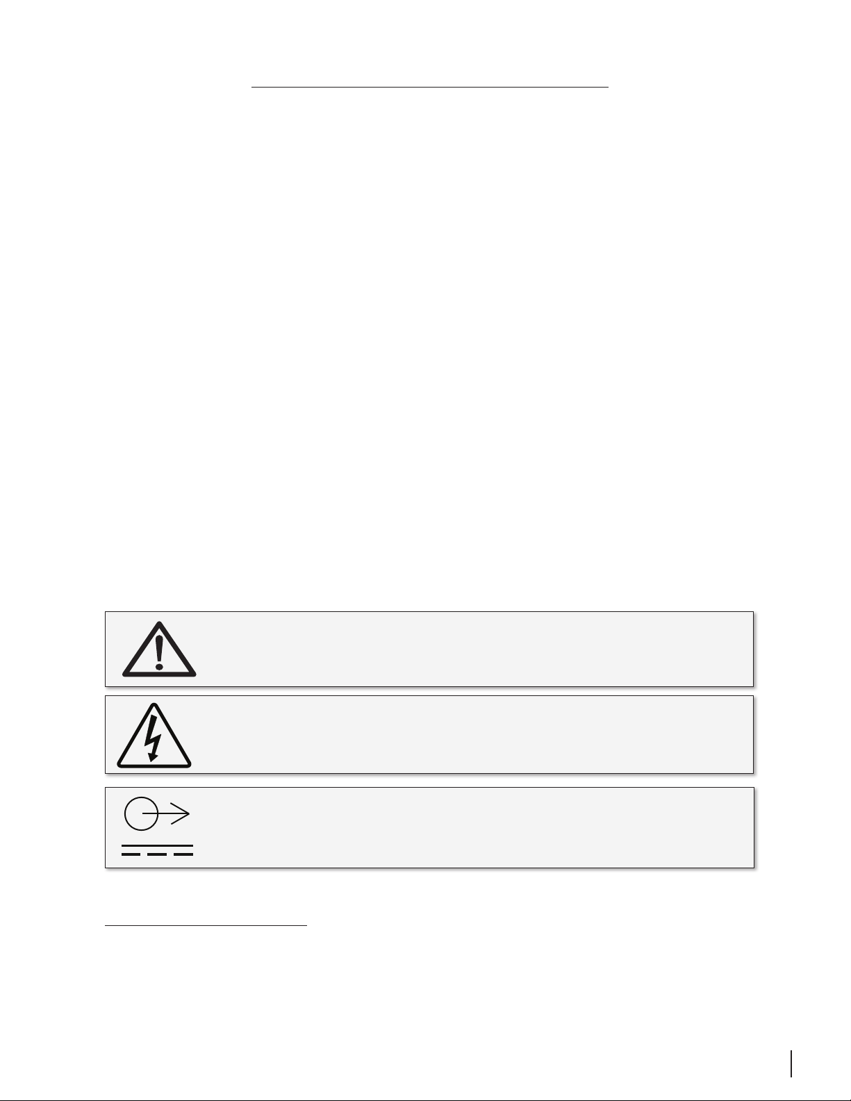
CAUTION: READ ACCOMPANYING DOCUMENTS
This symbol, located on the equipment and in this manual, refers to important
instructions. Read this manual thoroughly before operating this equipment.
WARNING: ELECTRICAL SHOCK HAZARD
This symbol, located on the equipment and in this manual, indicates the potential for
electrical shock hazard.
DC POWER OUTPUT
This symbol, located on the equipment and in this manual, indicates a DC power output
connection.
SERVICE INFORMATION
The Grace Design m906 contains no user serviceable components. Contact Grace Design for repair and
upgrade information. In the event that your Grace Design m906 needs to be returned to the factory,
contact us for a return authorization number.
grace design m906
owner’s manual
3
m906 key feaTures
power
headphone
GRACE DESIGN USA
y Multiple 5.1 and stereo analog inputs
y 24-bit/192kHz digital 5.1 and stereo inputs – AES3, S/PDIF, ADAT and TOSLINK formats
y s-Locktm PLL (Phase Lock Loop) for ultra-low jitter sample clock regeneration
y Precision main and headphone level controls with a 100dB gain range in 0.5dB steps
y All controls built into an elegant, compact desktop remote control unit
y All I/O and audio are routed in a 2U, 19” rack mount Audio Control Unit with an external 1U, ½ rack linear power
supply
y Multiple speaker set selection – two surround/stereo sets and a third stereo set
y High current reference headphone amplifier built in – one output on the remote control unit and an additional
output on the Audio Control Unit
y Comprehensive system level calibration (inputs, outputs, inter-channel balance, dim)
y Individual channel solo/mute
y Optional Downmix Module
y Optional AES Loop-Thru feature
y Balanced talkback microphone input with 48V phantom power with an activation switch on remote and an
additional external switch control jack
y Fixed level 5.1 DAC output for digital to analog transfers
y 5 year limited warranty on parts and labor
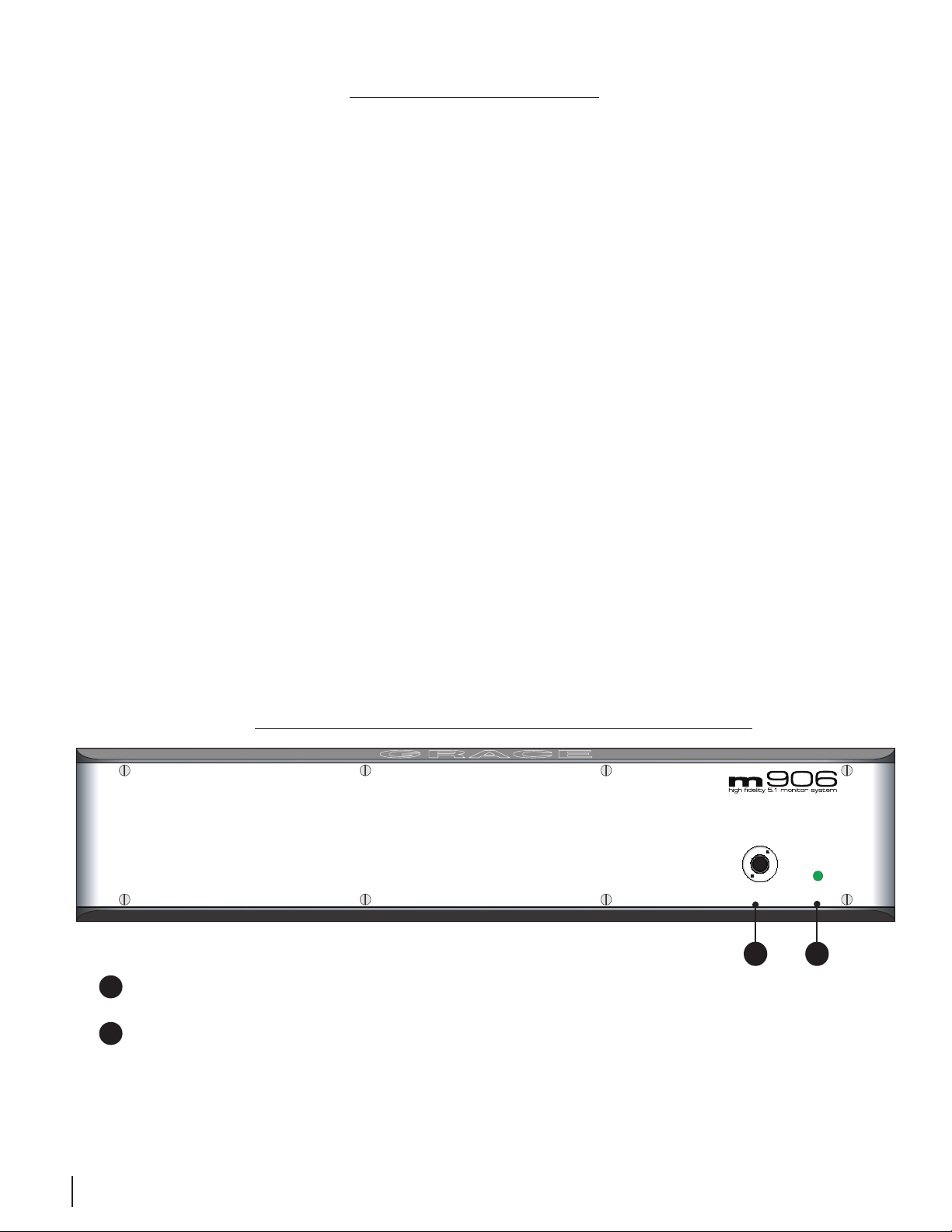
m906 audIo ConTrol unIT fronT panel
A
A
HEADPHONE OUTPUT The Audio Control Unit headphone output is provided via a ¼” TRS (Tip, Ring,
Sleeve) jack. This output runs parallel with the headphone jack on the remote unit.
B
POWER LED The green POWER LED is illuminated when power is received from the external power
supply to the rear panel mounted DC input.
B
grace design m906
4
owner’s manual
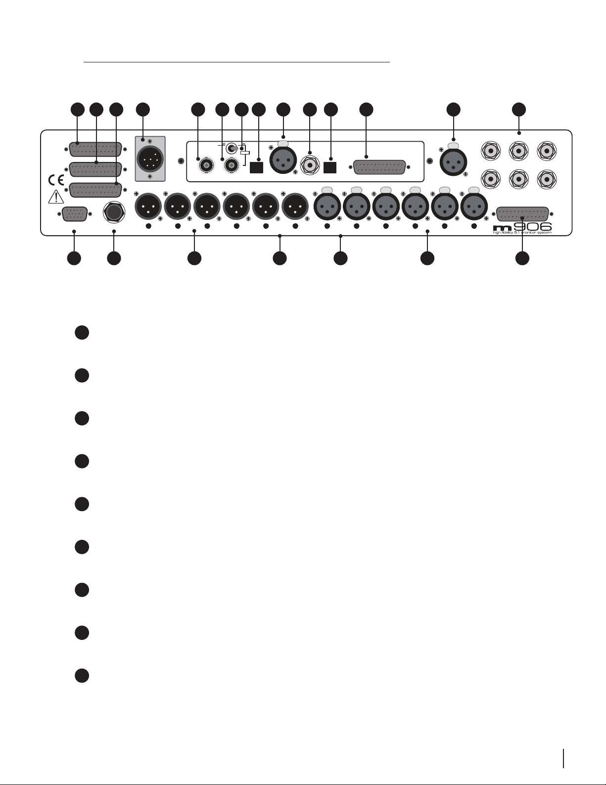
m906 audIo ConTrol unIT rear panel
tR
A
GRACE DESIGN USA
5.1 DAC OUT
5.1 CR OUT 2
5.1 CR OUT 1
REMOTE TB SW
O TSRQ
A
C
B
D
DC IN
L R
P U
5.1 DAC OUTPUT This female DB-25 connector supplies 5.1 fixed level balanced DAC output signals, wired to the Tascam DA-88 standard pinout.
B
5.1 CR OUT #2 This female DB-25 connector carries the balanced analog Control Room Output #2
signals for connection to a 5.1 speaker system, wired to the Tascam DA-88 standard pinout.
CR OUT 1
F
1M
CR OUT 2
IN
G H
75
load
L R
CUE OUT
E I
WORD CLOCK/
SUPERCLOCK
L R
PUSH
2
AES3
J
K
1
3
S/PDIF
PUSH
2
3
L R
CUE IN
L
DIGITAL INPUTS / SYNC
GRACE DESIGN AT103 906 DAC
AES3 x 4TOSADAT THRU
PUSH
PUSH
1
1
2
2
3
3
L R
1
2 CH 1
PUSH
2
3
M
PUSH
2
3
TB MIC
PUSH
1
1
2
3
LR
2 CH 2
Lef
1
PUSH
LS RS Sub
1
2
3
N
ightCenter
5.1 INPUT 2
5.1 INPUT 1
C
5.1 CR OUT #1 This female DB-25 connector carries the balanced analog Control Room Output #1
signals for connection to a 5.1 speaker system, wired to the Tascam DA-88 standard pinout.
D
DC IN This 6-pin male XLR DC input accepts the supplied cable from the m906’s external power
supply.
E
WORD CLOCK/SUPER CLOCK THRU This BNC connector is used to pass an external Word Clock or
Super Clock reference signal through to another digital device downstream of the m906.
F
WORD CLOCK/SUPER CLOCK IN This BNC connector allows the m906 to receive an external Word
Clock or Super Clock source to be used as a reference for locking the m906’s internal clocks.
G
WORD CLOCK TERMINATION SWITCH This switch is used to properly terminate a connection from
an external clock reference source to the m906 Word or Super Clock input.
H
ADAT INPUT This Lightpipe connector provides an 8-channel input from an ADAT format digital
source. 44.1kHz and 48kHz sample rates are supported.
I
AES3 STEREO INPUT This female XLR connector is used to receive a stereo AES3 format digital
signal.
grace design m906
owner’s manual
5

J
S/PDIF STEREO INPUT This RCA jack input accepts a S/PDIF format digital stereo signal.
K
TOSLINK STEREO INPUT This optical connector accepts a TOSLINK format digital stereo signal.
L
AES3 MULTI-CHANNEL INPUT This DB25 female connector accepts inputs from four AES3 format
digital sources. The first three AES3 inputs serve as the 5.1 digital input source (channels 1 through
6) and the remaining pair is available as the second 2 CH AES3 input (channels 7 and 8). Wired to
the Tascam DA-88 standard pinout. This connector also can provide four AES digital outputs with
the AES Loop-Thru option.
M
TB MIC INPUT This female XLR connector connects a talkback microphone to the m906 for control
room to studio communications. 48 Volt phantom power is provided.
N
5.1 UNBALANCED ANALOG INPUTS These six RCA jacks are used to input an unbalanced (–10dBV)
5.1 source into the m906.
O
REMOTE CONNECTOR This female DB15 (high density) connector allows connection between the
m906 Audio Control Unit and the remote control unit via the supplied remote cable.
P
TB SW JACK This ¼” TRS talkback switch jack is for connecting an external switch used to remotely
activate the talkback microphone function.
Q
CR OUT 1 and CR OUT 2 Analog, balanced stereo outputs for stereo control room output sets #1
and #2. These connections are wired in parallel with the left and right outputs of the corresponding 5.1 DB-25 control room outputs.
R
CUE OUT LEFT AND RIGHT An analog balanced stereo output for the CUE input signal. The talk-
back microphone signal is summed into this output. This output can also be configured to serve as
a third stereo control room output pair.
S
CUE IN LEFT AND RIGHT This input is for connecting a stereo cue signal to the m906, which can be
routed to the stereo cue outputs for studio talent monitoring and can be monitored directly in the
control room.
T
2 CH 1 and 2 CH 2 INPUT These are balanced analog stereo XLR inputs.
U
5.1 BALANCED ANALOG INPUTS This DB25 female connector accepts analog balanced (+4dBu)
signals for use as a 5.1 source input.
grace design m906
6
owner’s manual
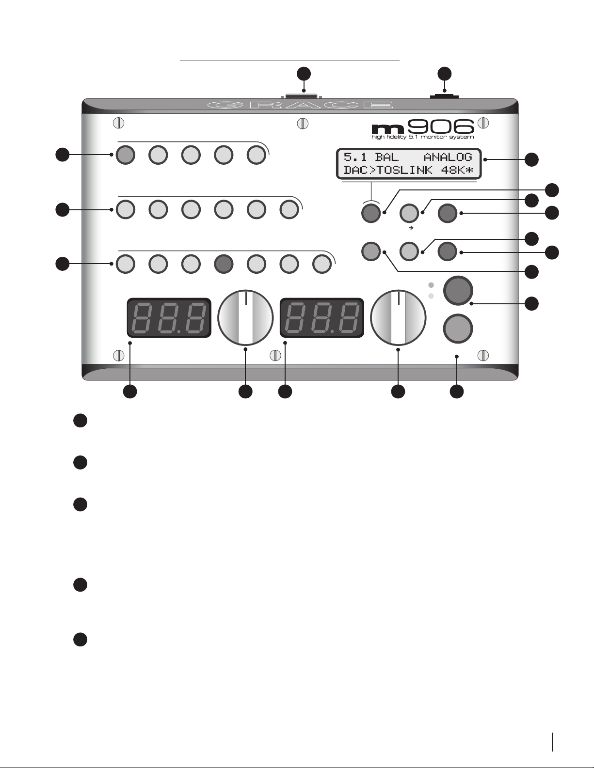
m906 remoTe ConTrol unIT
R
input
analog
A
5.1
BAL
input
5.1
UNBAL
digital
2ch
BAL1
2ch
BAL2
cue
Q
P
O
N
B
5.1
AES3
channel
C
Left
5.1
ADAT
2ch
AES3
2ch
AES3
solo/mute
Center Right
GRACE DESIGN USA
LS RS
2ch
S/PDIF
2ch
ADAT/TOS
Sub
main level / editheadphone level
solo/mute
mon cue
(spkr 3)
dimmono mute
calsel
1
2
spkr sel
talkback
M
L
K
J
I
D
A
INPUT ANALOG SWITCHES This row of five green LED illuminated switches is for selecting between
E
F
G
H
and monitoring any of the analog sources connected to the m906.
B
INPUT DIGITAL SWITCHES This row of six green LED illuminated switches is for selecting between
and monitoring any of the digital sources connected to the m906.
C
CHANNEL SOLO/MUTE SWITCHES These seven bi-colored switches are used to solo or mute any
individual channel being monitored by the m906. The first six switches engage solo or mute for
the relevant channel, while the solo/mute switch is used to toggle between solo or mute mode.
Additionally, pressing and holding the MUTE/SOLO Button will toggle the m906’s optional DOWNMIX feature.
D
HEADPHONE LEVEL DISPLAY This blue, 3 digit headphone level display shows the current relative
headphone output level value based on the position of the headphone level rotary encoder. The
range of this display is 0 to 100dB.
E
HEADPHONE LEVEL ROTARY ENCODER This stepped rotary encoder controls the headphone out-
put level in .5dB increments. When monitoring multichannel sources, pushing this encoder knob
allows the headphone source channels to be selected. Additionally, double clicking the encoder
alternately mutes or recalls the stored level preset.
grace design m906
owner’s manual
7

F
MAIN LEVEL/EDIT DISPLAY This blue, 3 digit main level/edit display shows the current relative main
speaker output level values based on the position of the main level rotary encoder. The range of
this display is 0 to 100dB. The display also shows edit values when the system is in CAL mode.
G
MAIN LEVEL/EDIT ROTARY ENCODER This stepped rotary encoder controls the main speaker
output levels in .5dB increments. This encoder is also used to adjust level offset calibration values
when in CAL mode.
H
TALKBACK SWITCH This red illuminated momentary action switch engages the talkback micro-
phone circuit for as long as the switch is depressed. Releasing the switch disengages talkback.
I
SPKR SEL SWITCH The speaker select switch is used to toggle between the available speaker out-
put sets. Each press of the switch lights the LED associated with each speaker set (1 or 2).
J
MONO SWITCH Pressing this green illuminated switch mono sums the stereo left and right chan-
nels.
K
MUTE SWITCH The mute switch is used to fully mute all audio output from the m906. The red
switch LED illuminates when active.
L
DIM SWITCH Pressing this illuminated switch reduces the monitoring level of the currently select-
ed speaker output set by 20dB (this value can be edited in CAL mode). Pressing the switch again
returns the system to its normal output monitoring levels.
M
CAL SWITCH Pressing the CAL switch activates calibration mode on the m906. When CAL mode is
active, the red LED CAL switch will flash. CAL mode is exited by pressing the switch again. Please
refer to the ‘Accessing the Cal Modes’ chapter of this manual for detailed information about m906
system calibration.
N
MON > CUE SWITCH The MON > CUE switch is an illuminated switch used for routing the selected
stereo input source to the CUE output. In addition, this switch may be configured to access a third
stereo speaker pair output.
O
SEL SWITCH The SEL switch is used to select between Word Clock or Super Clock when an external
clock reference source is used.
P
SYSTEM LCD This backlit LCD shows various m906 status settings, such as the input source select-
ed, current sample rate, s-Lock
Q
HEADPHONE AMPLIFIER JACK This ¼” TRS headphone output jack is provided on the remote con-
trol unit to access the integrated reference headphone amplifier.
R
REMOTE CONNECTOR This female DB15 connector is used to supply the remote unit with power,
headphone signal and serial communication.
tm
state, clock source, etc…
grace design m906
8
owner’s manual

unpaCkInG and InsTallInG your m906 sysTem
The m906 is shipped in two boxes.
Box 1 contains:
y the m906 Audio Control Unit
y external power supply
y AC power cord
y 6-pin XLR DC power cable
y small plastic bag containing four self-adhesive rubber feet
y warranty registration card
y some Grace Design literature for your reading pleasure
Box 2 contains:
y the remote control unit
y 25’ remote cable
y remote unit height/angle adjustment legs
y small plastic bag containing four self-adhesive rubber feet
OPEN AND INSPECT THE BOXES
Open both shipping boxes, carefully remove the m906 system components and put them aside. Before
you go any further, check to make sure the above listed components are included with your shipment.
If you believe something is missing, contact your friendly Grace Design dealer and they will make sure
you’re taken care of.
SAVE YOUR BOXES!!
We strongly encourage you to save all of the boxes and shipping materials supplied with your m906.
They are specially designed to properly protect these valuable components, and in the unlikely event
that you need to return them for service, only these OEM shipping materials can ensure their safe return
to our factory.
REGISTER YOUR UNIT
Also, we strongly urge you to register your unit with Grace Design. We provide a limited 5 year warranty
on all of our products, but if you don’t register your system it’s hard for us to help you if and when help
becomes necessary. So please take a few minutes to complete the enclosed warranty registration card
and mail it in, or simply go to the warranty registration form on our web site. Thank you!
grace design m906
owner’s manual
9
ConneCTInG The m906
Okay, let’s get started in making the necessary connections to get your m906 up and running. First thing
to do is mount the Audio Control Unit in a rack. If you’re not rack mounting the unit, you should attach
the supplied rubber feet on each corner of the chassis so you won’t scratch it or the surface you place
it on.
One important consideration is where to position the external power supply. The supplied cable to
connect the power supply to the Audio Control Unit is 8’ (2.8m) long. The power supply can be mounted
in a standard rack tray (not supplied) via the 10/32” mounting thread located towards the rear of the
supply on the bottom panel.
POWER CONNECTIONS
The Disconnect Device for the m906 system is the Mains plug or the Appliance Coupler
on the power supply cord. The Disconnect Device must remain accessible and operable.
The power supply cord supplied with the m906 must be connected to a mains outlet
with a protective earthing connection.
GROUNDING OPTIONS
In certain installations, it may be desirable to separate the m906’s signal ground from the power supply
chassis and earth grounds. Noise inducing ground loops can be broken while retaining the safety feature
of the grounded AC cable. The m906 should not be operated with a ground lift or “cheater” plug on the
AC power cord. Simply set the AUDIO GND toggle switch on the rear panel of the power supply unit to
the desired setting (ISO or EARTH).
CHECK LINE VOLTAGE SETTINGS
The power supply unit has been set from the factory to operate at the voltage required for your part of
the world. However, it’s important to double-check this in order to ensure no damage will come to the
unit if power is applied while the setting is incorrect.
LINE VOLTAGE SELECTOR
To change the line voltage, use a small screwdriver to pry open the voltage select door. Carefully remove
the voltage select cam and re-insert it with the desired voltage showing. Use Table 1 below for voltage
settings and fuse values.
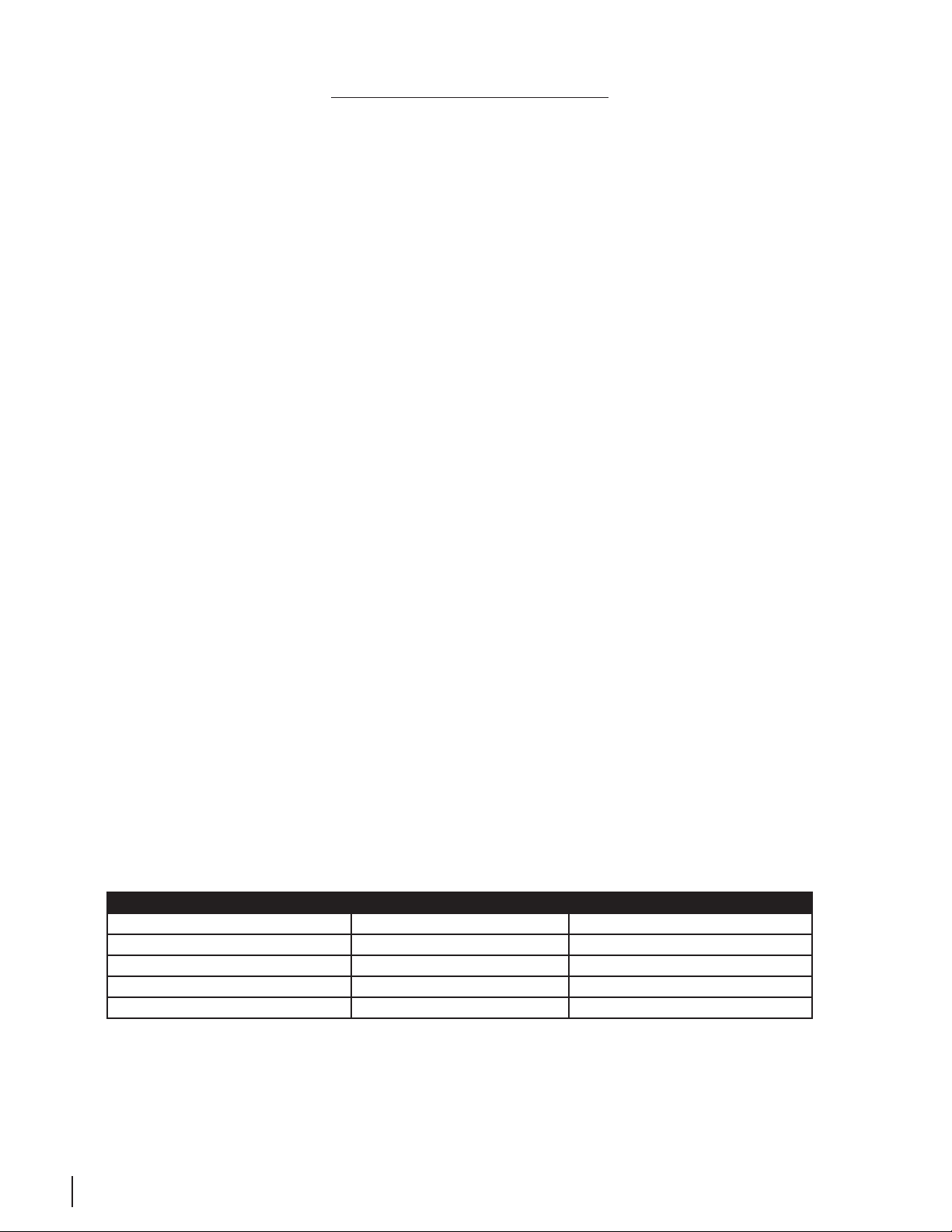
Table 1 Voltage and Fuse information
CAM SETTING LINE VOLTAGE FUSE VALUE
100V~ 100V~ 250V~ T 800mA L
120V~ 120V~ 250V~ T 800mA L
220V~ 220V~ 250V~ T 500mA L
240V~ 230V~ 250V~ T 500mA L
240V~ 240V~ 250V~ T 500mA L
grace design m906
10
owner’s manual
DC POWER CORD
The first connection to make is from the power supply unit to the main chassis with the supplied 6 pin
XLR DC power cord. Important: the DC power cable and the remote cable should be connected BEFORE the
AC power is turned on. This prevents incorrect power sequencing which can potentially cause damage to the
m906’s audio circuits.
Warning: A damaged DC power cord can create a shock hazard as Voltages of 72V DC
can be present. Do not operate the m906 with a damaged DC power cord. Replace a
damaged DC power cord with a replacement from Grace Design (WA047) only.
AC POWER CORD
Now connect the supplied AC cord to the power supply and then to an AC outlet with the supplied AC
cable. For safety, it is recommended that the cable be connected to a grounded outlet.
CONNECTING THE REMOTE CONTROL UNIT TO THE AUDIO CONTROL UNIT
The m906 remote control unit connects to the Audio Control Unit via a supplied, high quality 25’ cable.
Each end of the cable terminates in a male DB15 connector. This cable provides RS-422 serial data,
power and headphone signal to the remote.
Make the connection by securing the remote cable to the remote control unit and then attaching the
other end to the Audio Control Unit. Both ends of the cable are identical so it doesn’t matter which
end you connect to the remote or Audio Control Unit. Note: The HD15 connector on each end of the
remote cable does not use a “VGA” computer monitor pinout (see the cable wiring diagram section of
this manual). If you need a cable longer than 25 feet, an off-the-shelf VGA extension won’t work. Instead,
please call us at 303-443-7454 and we’ll help you out.
TUNING POWER ON
The power switch is located on the front panel of the Power Supply Unit. Switching the rocker switch
to the I position turns the power on. Switching the rocker switch to the
standby.
ATTACHING THE TILT ADJUSTMENT LEGS TO THE REMOTE CONTROL UNIT
The m906 remote control unit can be placed directly on a flat surface or can be tilted forward with the
pair of supplied legs. If you intend to place the remote on a flat surface, you should first attach the selfadhesive rubber feet (supplied) to each corner of the bottom of the chassis. This will prevent the unit
from scratching your surface and from the bottom panel of the remote from being scratched. The legs
for the remote are threaded on one end and screw into the threaded holes at the rear corners of the
bottom panel. The remote tilt angle can be adjusted slightly by screwing the legs in or out.
position sets the m906 in
grace design m906
owner’s manual
11

POWER SEQUENCE
Before powering up your m906, make sure your powered monitors or power amps connected to your
monitors are turned OFF, which will prevent any “popping” in your speaker systems. Once the m906
and the rest of your audio system are powered up, turn on the power to your speakers. When powering
down, we recommend that you first power off your speaker system and then power down the m906.
It should also be noted that while the power sequence will not damage headphones connected to the
m906, you should NOT be wearing them when power is applied or turned off.
sysTem ConneCTIons
5.1 DAC OUT - The fixed level balanced DAC output connector is wired to the Tascam DA-88 standard.
With CAL mode, the output level can be adjusted in 0.5dB steps. The factory default cal setting output
Voltage is +16dBu for 0dBFS.
5.1 CR OUT 1 and 5.1 CR OUT 2 - These are the multichannel control room outputs which are wired
to the Tascam standard pinout and carry the balanced Left, Center, Right, Left Surround, Right Surround
and Sub signals. The signal level on these connectors is controlled by the main level/edit encoder on
the remote control.
REMOTE CONNECTOR - Connects the m906 main chassis unit to the remote control unit. This DB15
connector carries RS244 serial data, DC power and headphone signals. The m906 ships with a 25’ cable.
While the serial data can travel several hundred feet we do not recommend cables longer than 50’ for
headphone use. Be sure to use the supplied 15 pin cable and not an off the shelf computer video cable.
If you need a longer cable contact your Grace Design dealer or call us directly.
TB SW JACK - The talkback switch input allows the connection of an external switch, such as a foot
switch, for remotely activating the talkback mic input on the m906. The input is a TRS jack and is used
with a “normally open” switching device. When using this jack, the talkback function can be activated at
both the remote control unit and the external remote switch.
DC IN - This 6 pin XLR connector carries the DC power from the power supply unit. +24V, -24V, +8V and
+48V are present. Connect this DC power cord BEFORE turning on the AC power at the power supply
unit.
CR OUT 1 and CR OUT 2 - These are the stereo XLR balanced control room outputs. They are
wired in parallel with the Left and Right signals from the corresponding 5.1 CR OUT #1 and #2 DB-25
connectors. Standard balanced XLR cables can be used with these outputs (pin 1 shield, pin 2 positive,
pin 3 negative).
CUE OUT - This is the stereo XLR balanced CUE output, which outputs the signal present on the CUE
INPUT connectors. Typically this output would be wired to your studio’s headphone cue system or it can
double as a third speaker output. Standard XLR balanced cables can be used with this output.
2 CH 1 and 2 CH 2 INPUTS - These are stereo XLR balanced inputs. Standard XLR balanced cables can
grace design m906
12
owner’s manual
 Loading...