

Grace m902 Owner's Manual
reference headphone
amplifier
OWNER’S MANUAL
Manual Rev G / Firmware v1.5
all contents © Grace Design/ Lunatec LLC
WELCOME
Thanks for purchasing the Grace Design m902 reference headphone amplifier. We build all our
products to be completely reliable and easy to use, so you can concentrate on producing great
sounding audio, not struggling with complicated equipment or difficult to use product manuals.
While the m902 has been designed to be straightforward to use, we do suggest that you spend a
little time familiarizing yourself with the features and operational functions that are contained in this
manual. Doing this now will make your experience with the m902 more enjoyable.
In the event that you encounter any technical or operational difficulties with this or any Grace Design
product, please feel free to contact us at 303-443-7454. Our office hours are from 9 to 5, Monday
through Friday, MST. Or you can e-mail your questions to: info@gracedesign.com
Also, please remember to visit our website www.gracedesign.com for the latest Grace Design product
information, owner’s manuals and technical documents.
Grace Design has been building audiophile quality products for the recording industry for over a
decade. The technology developed for the m902, and all of our products, has evolved through a
process of extensive listening, field testing and careful refinement.
Your new m902 amplifier represents a combination of absolutely pristine audio performance, robust
mechanical construction and bombproof reliability.
Regardless of what type of work you do, your m902 will faithfully serve as an invisible link between
your source audio and your headphones or speaker systems. We sincerely hope our products help you
achieve a new level of excellence in your work! -The Grace Design Team.
TABLE OF CONTENTS
Important Safety Information 3
m902 Key Features 4
m902 Frontpanel 5
m902 rearpanel 6
Unpacking and Installing your m902 6
Powering up the m902 7
Input Connections 8
Output Connections 9
Selecting an Input Source 9
About s-Locktm 10
About x-Feed 11
Accessing and Using the Submenu 12
Wireless Remote Control Operation 15
m902 Block Diagram 17
infrared Remote Commands 18
Specications 19
Cleaning and Maintenance 20
Warranty Information 20
Manual revisions 21
grace design m902
2
owner’s manual
IMPORTANT SAFETY INFORMATION
GENERAL
Indoor use only •
Ordinary Protection: This equipment should not be exposed to dripping or splashing. •
Avoid placing objects filled with liquids, such as vases or glasses, on this equipment. •
Class I Equipment (grounded type) •
Electrical rating: 100-120/220-240V~ 50-60Hz 25W •
Mains supply voltage fluctuations are not to exceed ±10% of the nominal supply voltage. •
Pollution Degree 2 •
Installation (Overvoltage) Category II for transient overvoltages. •
Maximum Relative Humidity: <80% •
Operation temperature range: 10 °C to 40 °C •
Storage and transportation temperature range –40 °C to 70 °C •
Maximum altitude: 3000m (9843 ft) •
Equipment suitable for continuous operation •
Weight: 2.3kg (5lbs) •
SAFETY MARKING SYMBOLS
CAUTION: READ ACCOMPANYING DOCUMENTS. This symbol, located on the equipment
and in this manual, refers to important instructions. Read this manual thoroughly before
operating this equipment.
This symbol, located on the equipment and in this manual, indicates the potential for
electrical shock hazard.
SERVICE INFORMATION
The Grace Design m902 contains no user serviceable components. Contact Grace Design for repair
and upgrade information. In the event that your Grace Design m902 needs to be returned to the
factory, contact us for a return authorization number.
grace design m902
owner’s manual
3

m902 KEY FEATURES
Stereo analog inputs - balanced (+4dbu) XLR and unbalanced (-10dbv) RCA. •
Ultra low distortion 24-bit /192khz DAC accepts stereo digital input sources in AES3, S/PDIF and •
TOSLINK (optical) formats with auto sample rate detection and digital de-emphasis filter.
USB input provides a convenient way for users to enjoy a reference quality monitoring experience •
when connected to their computer. This interface supports 16-bit audio at 44.1 Or 48kHz sample
rates.
s-locktm dual stage PLL (phase lock loop) circuitry for the ultimate in low jitter digital signal stability •
and sonic integrity.
Unbalanced line level outputs (m902) are provided via rca jacks on the rear panel for connection to •
stereo monitors.
Balanced line level outputs (m902b) are provided via ¼” tip-ring-sleeve (TRS) jacks on the rear panel •
for connection to stereo monitors.
Front panel rotary encoder provides precision level control of both headphone and line output •
levels. Level adjustments are made in 0.5db steps within a 95db range.
0.05db channel level matching to ensure true stereo balance at any monitoring level. •
A large, blue 7-segment display is used to show headphone and stereo main output levels. •
Calibration mode enables left/right balance adjustment for both headphone and mains outputs. •
There’s also a display dim mode that turns off all led’s except for the main power switch led.
X-feed (crossfeed) simulates the acoustics of a loudspeaker listening environment which can •
significantly improve imaging while reducing listening fatigue when using headphones. This
feature employs carefully designed signal cross-feed, filtering and delay circuits to simulate hrtf
(head related transfer functions).
High current transimpedance output amplifier design drives 8 ohm loads. The m902 was specifically •
designed with low impedance headphones in mind.
Only the highest quality 0.5% metal film resistors are used throughout and there are no electrolytic •
capacitors in the signal path. Sealed gold contact relays are used for all signal switching.
Infrared remote control for level control, left/right balance, mute and more when using the optional •
remote control unit.
5 Year limited warranty on parts and labor. •
grace design m902
4
owner’s manual
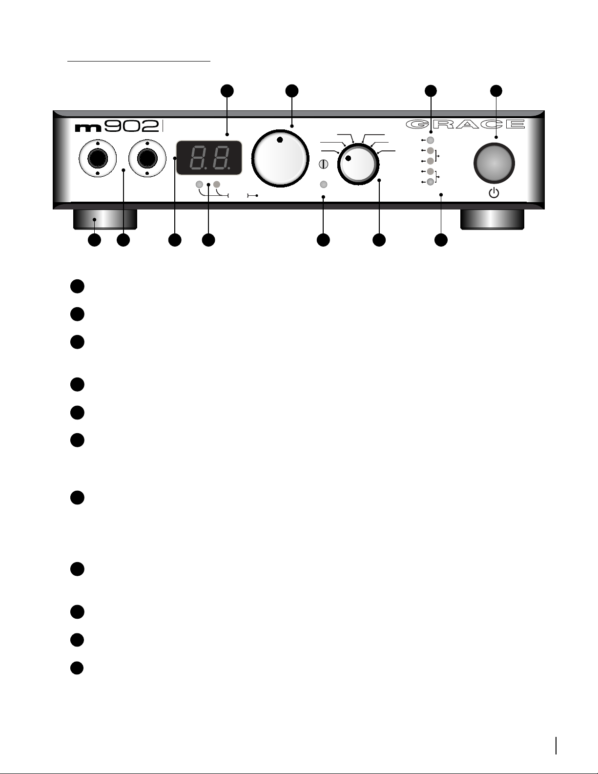
m902 FRONTPANEL
FS
44
48
88
96
176
192
-Lock
INPUT
AES
BAL
UNBAL
S/PDIF
TOS
USB
xfeed
VOLUMEOUTPUTS
phonesline
push
reference headphone
amplifier
s
G
K
A
ILLUMINATED POWER SWITCH -
B
S-LOCK INDICATOR LED -
C
SAMPLE RATE INDICATOR LEDS -
J
H
illuminates when s-lock is active.
source.
F
EI
D
B
C
illuminates green when unit is powered on.
auto sample rate detection from selected digital input
A
D
ROTARY INPUT SELECTOR SWITCH -
E
CROSSFEED INDICATOR LED -
F
OUTPUT LEVEL/EDIT ROTARY ENCODER -
crossfeed circuitry is user activated in submenu.
selects between all available inputs.
This stepped rotary encoder controls the
selected output level in .5dB increments. This encoder is also used to adjust other settings found
in the submenu.
G
OUTPUT LEVEL/SUBMENU DISPLAY -
This blue, 2 digit display shows the current relative
output level values based on the position of the main level rotary encoder. The range of this
display is 0 to 99. Note the decimal represents a 0.5dB increment. This display is also used to give
the user information in the submenu.
H
OUTPUT SELECTION LEDS –
These LEDS indicate which output is currently selected by the
user and under interface control.
I
INFRARED REMOTE RECEIVER –
J
HEADPHONE OUTPUTS –
K
FEET -
four custom machined removable metal feet with neoprene inserts.
Two stereo headphone output jacks wired in parallel.
Receiver used for optional wireless remote control.
grace design m902
owner’s manual
5

m902 REARPANEL
USB TOSLINK AES3
UNBAL INLINE OUT
BAL IN
S/PDIF
L
L
R
R
1
3
PUSH
2
1
3
PUSH
2
1
3
PUSH
2
120Vac
USB TOSLINK AES3
UNBAL INLINE OUT
BAL IN
S/PDIF
L
L
R
R
1
3
PUSH
2
1
3
PUSH
2
1
3
PUSH
2
120Vac
I
G
H
m902
m902B (with balanced line outputs)
E
E
C
B
A
D
UNPACKING AND INSTALLING YOUR m902
The m902 is shipped in one box which contains: the m902 unit, an AC power cord, a small plastic bag
containing four hand-threaded machined metal feet, a warranty registration card and some additional
Grace Design literature.
OPEN AND INSPECT THE BOX
Open all shipping boxes, carefully remove the m902 and put it aside. Before you go any further, check
to make sure the above listed components are included with your shipment. If you believe something
is missing, contact your friendly Grace Design dealer and they will make sure you’re taken care of.
SAVE YOUR BOX!!
We strongly encourage you to save the box and shipping materials supplied with your m902. They are
specially designed to properly protect these valuable components, and in the unlikely event that you
grace design m902
6
owner’s manual
A
BALANCED ANALOG INPUT
B
UNBALANCED ANALOG INPUT
C
UNBALANCED LINE OUTPUT
D
BALANCED LINE OUTPUT
E
AES DIGITAL INPUT
F
TOSLINK DIGITAL INPUT
G
S/PDIF DIGITAL INPUT
H
USB DIGITAL INPUT
I
AC IEC INPUT MODULE
need to return them for service, only these OEM shipping materials can ensure their safe return to our
factory.
REGISTER YOUR UNIT!
Also, we strongly urge you to register your unit with Grace Design. We provide a limited 5 year
warranty on all of our products, but if you don’t register your system, it’s hard for us to help you if and
when help becomes necessary. So please take a few minutes to complete the enclosed warranty
registration card and mail it in, or you can simply go to the warranty registration form on our web site.
Thank you!
INSTALLING THE FEET AND/ OR RACKMOUNTING
The m902 is designed to either be placed on a stable surface in your studio or listening environment,
or be rackmounted. If you don’t plan to rackmount your m902, first install the 4 supplied metal/rubber
feet. Simply thread (hand tighten only) theses supplied feet by hand into the 4 vacant threaded holes
in each corner of the underside of the m902.
For rackmount installation, the m902 chassis has a #10-32 threaded insert mounting hole on the
bottom towards the back. Two m902s can be mounted side by side in a standard 1U rack tray. Use a
#10-32 x 1/2” or a #10-32 x 3/8” machine screw. Do not use a screw longer than 1/2”.
POWERING UP THE m902
Okay, let’s get started in making the necessary connections to get your m902 up and running.
POWER CONNECTIONS
The Disconnect Device for the m902 system is the Mains plug or the Appliance Coupler
on the power supply cord. The Disconnect Device must remain accessible and operable.
The power supply cord supplied with the m902 must be connected to a mains outlet
with a protective earthing connection.
CHECK LINE VOLTAGE SETTINGS
The IEC power entry module has been set from the factory to operate at the voltage required for your
part of the world. However, it’s important to double-check this in order to ensure no damage will
come to the unit if power is applied and the setting is incorrect.
LINE VOLTAGE SELECTOR
To change the line voltage, remove the AC power chord from the power inlet then use a small
screwdriver to pry open the voltage select door. Carefully remove the voltage select cam and re-insert
it with the desired voltage showing. Use the table below for voltage settings and fuse values. Note that
time delay or “slow blow” fuses are required.
Voltage and Fuse information
CAM SETTING LINE VOLTAGE FUSE VALUE
100V~ 100V~ 250V~ T 250mA L
120V~ 120V~ 250V~ T 250mA L
220V~ 220V~ 250V~ T 125mA L
240V~ 230V~ 250V~ T 125mA L
240V~ 240V~ 250V~ T 125mA L
grace design m902
owner’s manual
7
 Loading...