

Grace m802 Owner's Manual
remote microphone preamplifier
Owner’s Manual
Preamplifier firmware version
Remote firmware version
Manual Revision
all contents © Grace Design/ Lunatec LLC
H
3.0
3.1

Welcome
Thank you for purchasing the Grace Design m802 preamplifier system. With the combination of unmatched
sonic performance, remote control capability and total reliability, the m802 is the ultimate, state of the art microphone preamplifier solution.
We have designed the m802 to be as easy and intuitive to use as possible. However, we strongly recommend
that you read this product manual thoroughly to familiarize yourself with the unique features and capabilities
of the m802.
Also, please do not hesitate to contact us directly if you have any questions, comments, or concerns with your
new m802 microphone preamplifier system. Thanks for reading and happy recording!!
-The Grace Design Team
Table of Contents
Welcome 2
Important Safety Information 3
Overview 4
Front Panel Diagram 5
m802 RCU Diagram 5
m802 Rearpanel Diagram 6
m802 Rearpanel with A/D Converter Diagram 6
m802 Power Supply Diagram 7
Installation 7
Control Data Connections 9
Preamplifier Operation / Modes 11
A/D Converter Sensitivity Calibration 16
Operation within Pro Tools 18
Remote Control Unit Operation 19
Cable Diagrams 21
Specifications 23
Cleaning and Maintenance 25
Warranty Information 25
Manual Revisions 26
2
Important Safety Information
GENERAL
Indoor use only
Ordinary Protection: This equipment should not be exposed to dripping or splashing.
Avoid placing objects filled with liquids, such as vases or glasses, on this equipment.
Class I Equipment (grounded type)
Electrical rating: 100-120/220-240V~ 50-60Hz 25W
Mains supply voltage fluctuations are not to exceed ±10% of the nominal supply voltage.
Pollution Degree 2
Installation (Overvoltage) Category II for transient overvoltages.
Maximum Relative Humidity: <80%
Operation temperature range: 10 °C to 40 °C
Storage and transportation temperature range –40 °C to 70 °C
Maximum altitude: 3000m (9843 ft)
Equipment suitable for continuous operation
Weight: preamplifier - 6.7kg (14.7lbs) / power supply unit - 2.8kg (6.25lbs)
SAFETY MARKING SYMBOLS
CAUTION: READ ACCOMPANYING DOCUMENTS
This symbol, located on the equipment and in this manual, refers to important instructions. Read this manual thoroughly before operating this equipment.
WARNING: ELECTRICAL SHOCK HAZARD
This symbol, located on the equipment and in this manual, indicates the potential
for electrical shock hazard.
DC POWER OUTPUT
This symbol, located on the equipment and in this manual, indicates a
DC power output connection.
SERVICE INFORMATION
The Grace Design m802 contains no user serviceable components. Contact Grace Design for repair and upgrade
information. In the event that your Grace Design m802 needs to be returned to the factory, contact us for a return authorization number.
3

Overview
SYSTEM COMPONENTS
The m802 system consists of an 8 channel preamplifier chassis, a power supply chassis, and an optional remote
control unit (referred to as the RCU in the rest of this manual). The preamplifier chassis contains 8 audio amplifier PCBs, a micro controller PCB, and a front panel control interface. For remote control communications, the
2
preamplifier chassis is equipped with two D-sub 9 pin connectors which carry Philips I
signals, as well as MIDI IN and OUT connectors. The use of an external DC power supply unit ensures that no
power line interference can compromise the performance of the sensitive microphone amplifier circuits.
As well as the standard 48V phantom powered microphone inputs, the m802 can be ordered with optional 130V
inputs for use with the DPA (formerly B&K) high voltage microphones. These microphones employ a high voltage transformerless impedance conversion circuit, which is not subject to the limitations of the 48V phantom
powering standard. However, being unbalanced, the DPA 130V microphones benefit greatly from short cable
runs from microphone to preamplifier.
Additionally, an optional extremely high performance 8-channel analog-to-digital converter module is available for the m802. This converter module supports sample rates up to 192kHz at 24bit resolution.
The RCU features an expanded version of the preamplier front panel interface and has a single I
RS-422 bus connector as well as a DC power Jack.
C and RS-485 / RS-422
2
C / RS-485 /
REMOTE CONTROL OPTIONS
The m802 preamplifier can be controlled by the RCU, via MIDI, or directly from its front panel. The RCU connects
2
to the preamplifier via an I
devices in the system. In an m802 system, the RCU is the master and all of the preamplifiers are slaves. The data
on the display of the RCU is echoed back from the preamplifier so it shows the actual status of the preamplifier.
For example, when you tell a preamplifier to change its gain at the RCU, the RCU will send the gain change command to the preamplifier and then ask the preamplifier what its current gain setting is. The RCU will then update
its own display to reflect the change. This gives the user absolute confidence that what is visible on the display is
exactly what is happening at the preamplifier. If the RCU is disconnected from the preamplifier(s), the data fields
in the display will go blank, but the preamplifiers will continue to operate normally.
The RCU can control up to 8 preamplifiers (64 channels) by connecting it to one preamplifier and then connecting the remaining preamplifiers together with I
control signal can be sent up to 1000 feet, in RS-485 / RS-422 over 3000 feet. Using the adapters included with
the RCU, standard microphone cable can be used for this interface (except for RS-422 connections). Only one
RCU can be connected to a system at any time.
The m802 can also be controlled via MIDI. When the m802 sees any activity on its MIDI input port, it automatically switches into MIDI control mode. In this mode, the m802 will emulate a AVID PRE microphone preamplifier.
After a period of 16 seconds with no activity on the MIDI input port, the m802 will automatically revert back to
its normal control mode. See the MIDI Control section of this manual for more details on the MIDI control mode.
C, RS-485 or RS-422 signal, which makes a parallel connection between all of the
2
C / RS-485 / RS-422 cables in a daisy chain fashion. In I2C mode,
4

Front Panel Diagram
+48V
GROUP
DATA
(push)
1 2 3 4 5 6 7
1. +48 Volt phantom power pushbutton
2. GROUP pushbutton
3. Ø phase reverse pushbutton
5. DATA encoder with pushbutton
6. SETUP select pushbutton
7. PEAK indicator reset pushbutton
4. LCD display 64x240 pixels
m802 RCU Diagram
remote microphone preamplifier
PEAK
SETUP
8
48V
GROUP
VIEW SETUP
1 2 3 4 5 6 7
1. +48 Volt phantom power pushbutton
2. Ø phase reverse pushbutton
3. GROUP pushbutton
4. VIEW / peak indicator reset pushbutton
5. SETUP select pushbutton
10
9
8
CHANNEL SELECT
GAIN / EDIT
push
6. 7-segment LED display
7. DATA encoder with pushbutton
8. Page Up / Down pushbuttons
9 Channel Select pushbuttons
10. LCD display 64x240 pixels
5
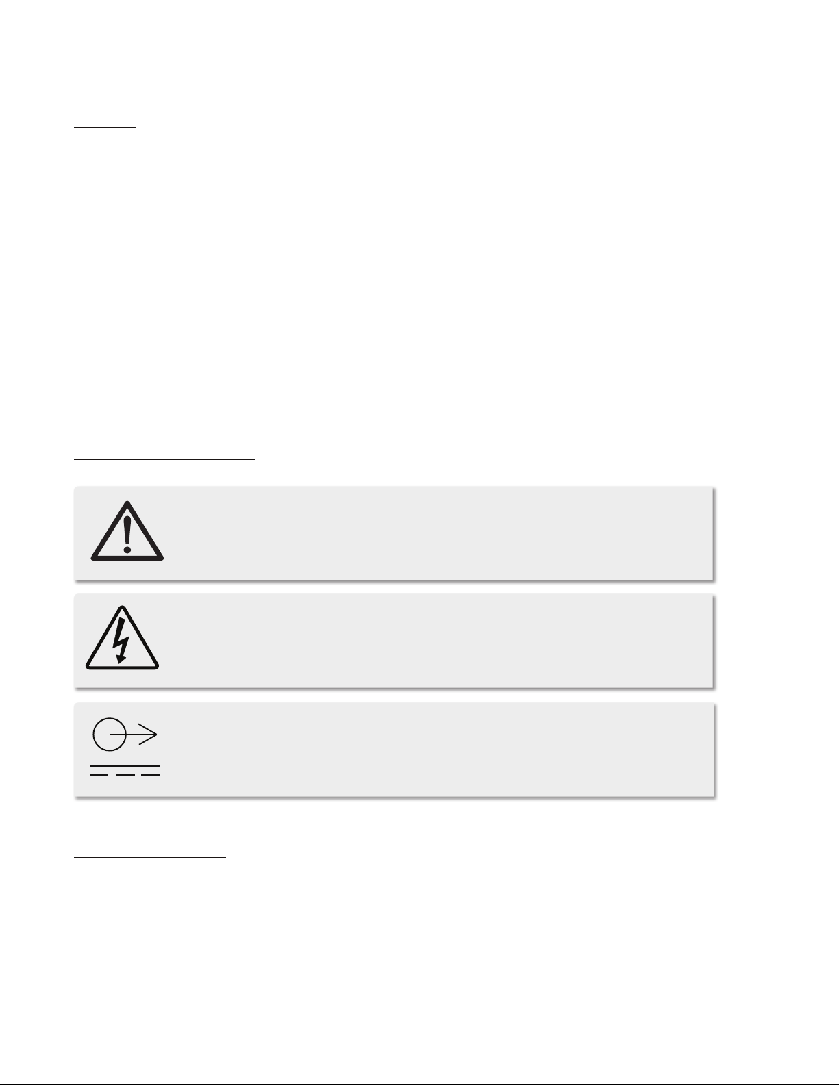
m802 Rearpanel Diagram
CONTROL
I2C / RS485 / RS422
MIDI
I2C / RS485 / RS422
DC IN
IN
OUT
GRACE DESIGN USA
MIC IN
LINE OUT
1 2 3 4 5 6
1. MIDI In / Out
2. DC Power Input
2
3. I
C, RS-485, RS-422 remote connections
4. DB25 Line Output
5. XLR Line Output
6. XLR Mic Input
m802 Rearpanel with A/D Converter Diagram
CONTROL
I2C / RS485 / RS422
MIDI
I2C / RS485 / RS422
DC IN
IN
OUT
GRACE DESIGN USA
MIC IN
LINE OUT
MIC IN
12345678
LINE OUTLINE OUT
12345678
LINE OUT
12345678
MIC IN
12345678
LINE OUTLINE OUT
12345678
LINE OUT
12345678
Digital Output Option A
includes 2 sets of 8 channel AES3 outputs on
DB25, Word Clock in and Out, and 1 set of AES3id outputs on 4 BNC connectors.
Digital Output option B
inculdes 2 sets of 8 channel AES3 outputs on
DB25, Word Clock in and Out, and 2 8 channel
ADAT / Lightpipe outputs.
6
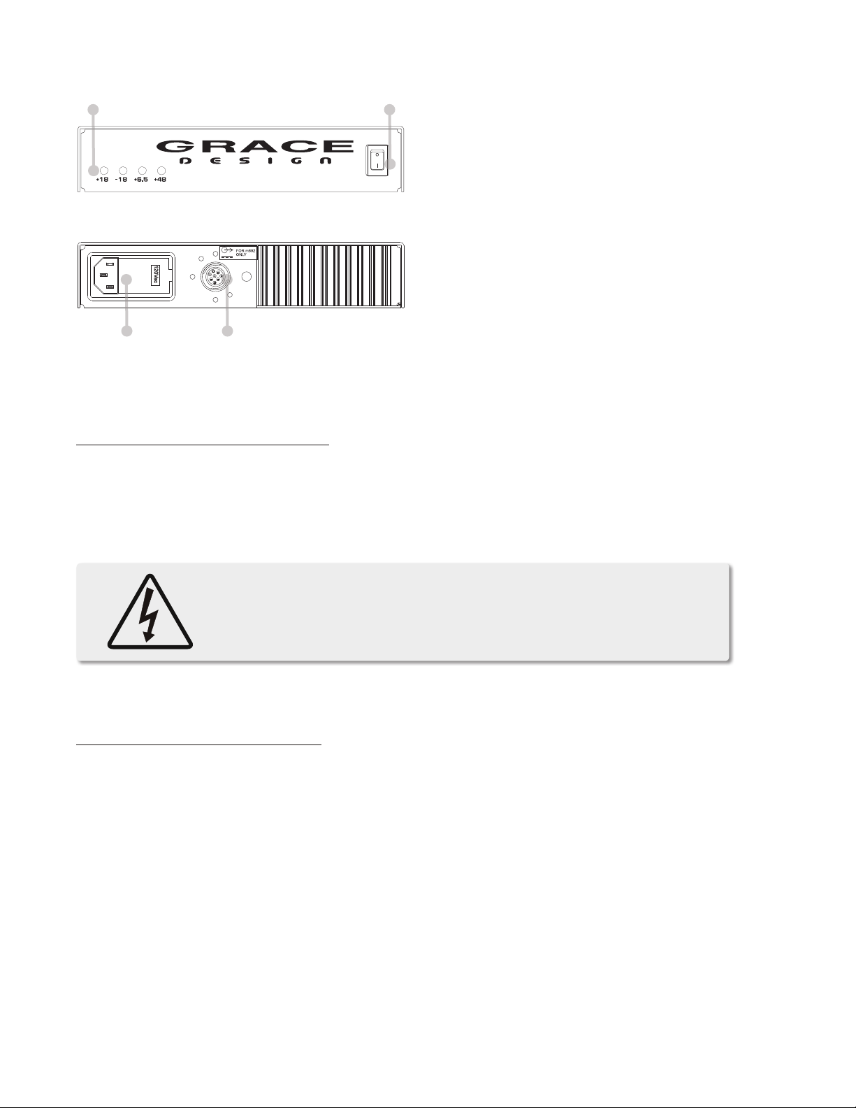
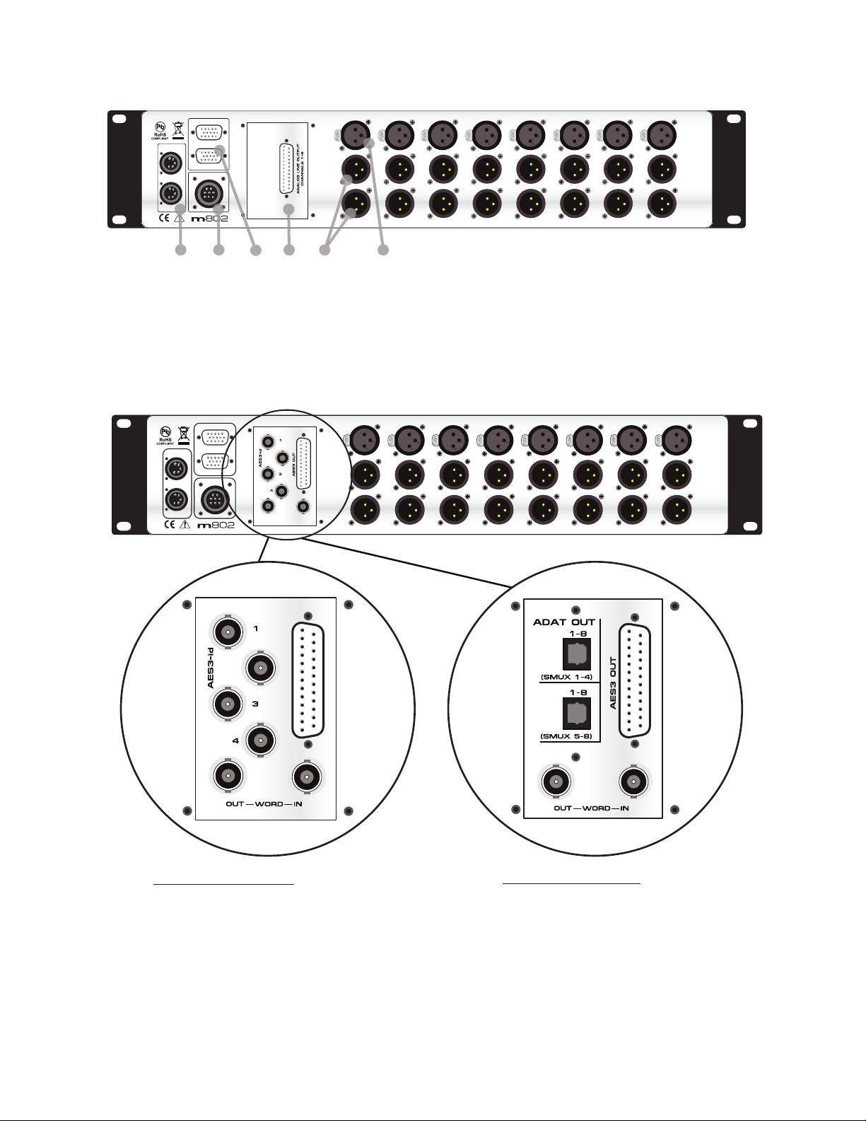
m802 Power Supply Diagram
1 2
CAUTION: ALWAYS CONNECT DC POWER
CORD BEFORE TURNING ON MAIN POWER
front
1.
LED Voltage indicators
2.
Power switch
3.
AC line input
4.
DC output
3 4
rear
Installation
PREAMPLIFIER POWER CONNECTIONS
An 8’ (2.8m) DC power cord is supplied to connect the power supply unit to the preamplifier unit. This cord can
be identified by the 8 pin circular connectors at each end.
Please note that the DC power cord should be connected before the AC power is turned on. This prevents incorrect power sequencing which can cause damage to the audio circuits.
Warning: A damaged DC power cord can create a shock hazard as Voltages of
66VDC (148VDC with the DPA Input option) can be present. Do not operate the
m802 with a damaged DC power cord. Replace a damaged DC power cord with
a replacement from Grace Design (WA084) only.
To avoid any interference with the low level audio circuitry, we recommend to locate the power supply at least
3’ (1m) from the preamplifier unit.
POWER SUPPLY UNIT CONNECTIONS
A standard AC power cable is included. For safety, the power supply cord must be connected to a grounded
outlet.
AC input voltage settings can be adjusted for 100V, 120V, 220V and 240V operation at 50-60Hz. If your voltage
is 230V, use the 240V setting. From the rear of the power supply unit, open the trap door next to the IEC power
inlet with a small screwdriver. Carefully pull the voltage select cam straight out and then insert with the desired
voltage showing. Do not try to rotate the cam while it is in the power input module. Replace the fuses with the
proper value selected from the fuse value table below (figure 1). Be sure to use a time delay type fuse with a
250V rating.
7

CAM SETTING LINE VOLTAGE FUSE VALUE
100V~ 100V~ 250V~ T 800mA L
120V~ 120V~ 250V~ T 800mA L
220V~ 220V~ 250V~ T 500mA L
240V~ 230V~ 250V~ T 500mA L
240V~ 240V~ 250V~T 500mA L
figure 1 / fuse value table
CHECK LINE VOLTAGE SETTINGS
The power supply unit has been set from the factory to operate at the voltage required for your part of the
world. However, it’s important to double-check this in order to ensure no damage will occur to the unit if power
is applied while the setting is incorrect.
TURNING THE POWER ON
The power switch is located on the front panel of the Power Supply Unit. Switching the rocker switch to the I
position turns the mains power on. Switching the rocker switch to the O position turns the mains power o.
REMOTE CONTROL UNIT POWER CONNECTION
The RCU is powered with the supplied AC wall adapter. It is recommended that the I2C, RS-485 or RS-422 data
connections be made before applying power to the RCU. Simply plugging the 2.1mm barrel connector into the
DC power jack turns the power on. The m802 RCU is rated for 6.0-7.5V / 0.5A DC. (+) is in the center and (–) is
on the outside sleeve.
AUDIO CONNECTIONS
Standard microphone input connections are made via female XLR connectors with pin 2 positive, pin 3 negative
and pin 1 ground. 48V phantom power is supplied on pins 2 and 3. DPA® 130V microphone connections are
made via the female 4 pin XLR connectors with audio on pin 4, 130V on pin 3 and ground on pin 1.
On standard m802 preamp channels, two male XLR output connectors are available with pin 2 positive, pin 3
negative and pin 1 ground. (There is one male XLR output connector available on 130V DPA cards.) An additional set of parallel outputs is provided with a 25 pin D-sub connector (See CABLE DIAGRAMS p. 21) NOTE:
this output is not available if the optional A/D converter module is installed. All output connectors can be used
simultaneously.
If the output is to be used unbalanced, pin 1 should be connected to signal ground and pin 2 to signal hot. Due
to the nature of the balanced output stage, pin 3 should be left open for unbalanced operation (See CABLE
DIAGRAMS p. 21). Note: This will provide a signal of positive absolute polarity when the preamplier is being
used with a microphone which produces a positive voltage on pin 2 with positive air pressure on the front of the
diaphragm. While a vast majority of microphones conform to this standard a few do not. Use the phase reverse
switch to compensate if necessary.
DIGITAL AUDIO CONNECTIONS
If the optional A/D converter module is installed, multiple digital outputs are available. The routing of the preamp outputs to the A/D converter is xed. Each preamp channel feeds the corresponding converter channel
(1-8). The DB25 pin provides 8 stereo AES outputs, which can be congured for single or dual wire operation.
8
 Loading...