

Grace m801 Owner's Manual
m801
microphone preamplifier
Manual RevB
OWNER’S MANUAL
all contents ©2006 Grace Design/ Lunatec LLC

WELCOME
Thank you for purchasing the Grace Design m801 microphone preamplifier. With the
combination of unmatched sonic performance and total reliability, the m801 is the ultimate, state of the art microphone preamplifier solution.
We have designed the m801 to be as easy and intuitive to use as possible. However,
we strongly recommend that you read this product manual thoroughly to familiarize
yourself with the unique features and capabilities of the m801.
Also, please do not hesitate to contact us directly if you have any questions, comments,
or concerns with your new m801 microphone preamplifier. Thanks for reading and
happy recording!!
-The Grace Design Team
Contents
WELCOME 2
IMPORTANT SAFETY INFORMATION 3
FRONT PANEL CONTROLS 4
REARPANEL CONNECTIONS 5
POWER SUPPLY 5
INSTALLATION 6
PREAMPLIFIER OPERATION 7
MAINTENANCE 8
SPECIFICATIONS 11
CLEANING AND MAINTENANCE 12
WARRANTY INFORMATION 12
grace design m801
2
owner’s manual

IMPORTANT SAFETY INFORMATION
GENERAL
•Indoor use only
•Ordinary Protection: This equipment should not be exposed to dripping or splash-
ing.
•Avoid placing objects filled with liquids, such as vases or glasses, on this equipment.
•Class I Equipment (grounded type)
•Electrical rating: 100-120/220-240V~ 50-60Hz 60W
•Mains supply voltage fluctuations are not to exceed ±10% of the nominal supply
voltage.
•Pollution Degree 2
•Installation (Overvoltage) Category II for transient overvoltages.
•Maximum Relative Humidity: <80%
•Operation temperature range: 10 °C to 40 °C
•Storage and transportation temperature range –40 °C to 70 °C
•Maximum altitude: 3000m (9843 ft)
•Equipment suitable for continuous operation
•Weight: preamplifier - 6.8kg (15lbs) / power supply unit - 2.8kg (6.25lbs)
SAFETY MARKING SYMBOLS
CAUTION: READ ACCOMPANYING DOCUMENTS
This symbol, located on the equipment and in this manual, refers to important instructions. Read this manual thoroughly before operating this equipment.
WARNING: ELECTRICAL SHOCK HAZARD
This symbol, located on the equipment and in this manual, indicates the
potential for electrical shock hazard.
DC POWER OUTPUT
This symbol, located on the equipment and in this manual, indicates a DC
power output connection.
SERVICE INFORMATION
The Grace Design m801 contains no user serviceable components. Contact Grace Design for repair and upgrade information. In the event that your Grace Design m801
needs to be returned to the factory, contact us for a return authorization number.
grace design m801
owner’s manual
3
+48V +48V +48V +48V +48V +48V +48V +48V
ribbon ribbon ribbon ribbon ribbon ribbon ribbon ribbon
- - - - - - - -20dB 20dB 20dB 20dB 20dB 20dB 20dB 20dB
GRACE DESIGN USA
20 20 20 20 20 20 20 20
30 30 30 30 30 30 30 30
40 40 40 40 40 40 40 40
50 50 50 50 50 50 50 50
60 60 60 60 60 60 60 60
2 3
4
5 6 7 81
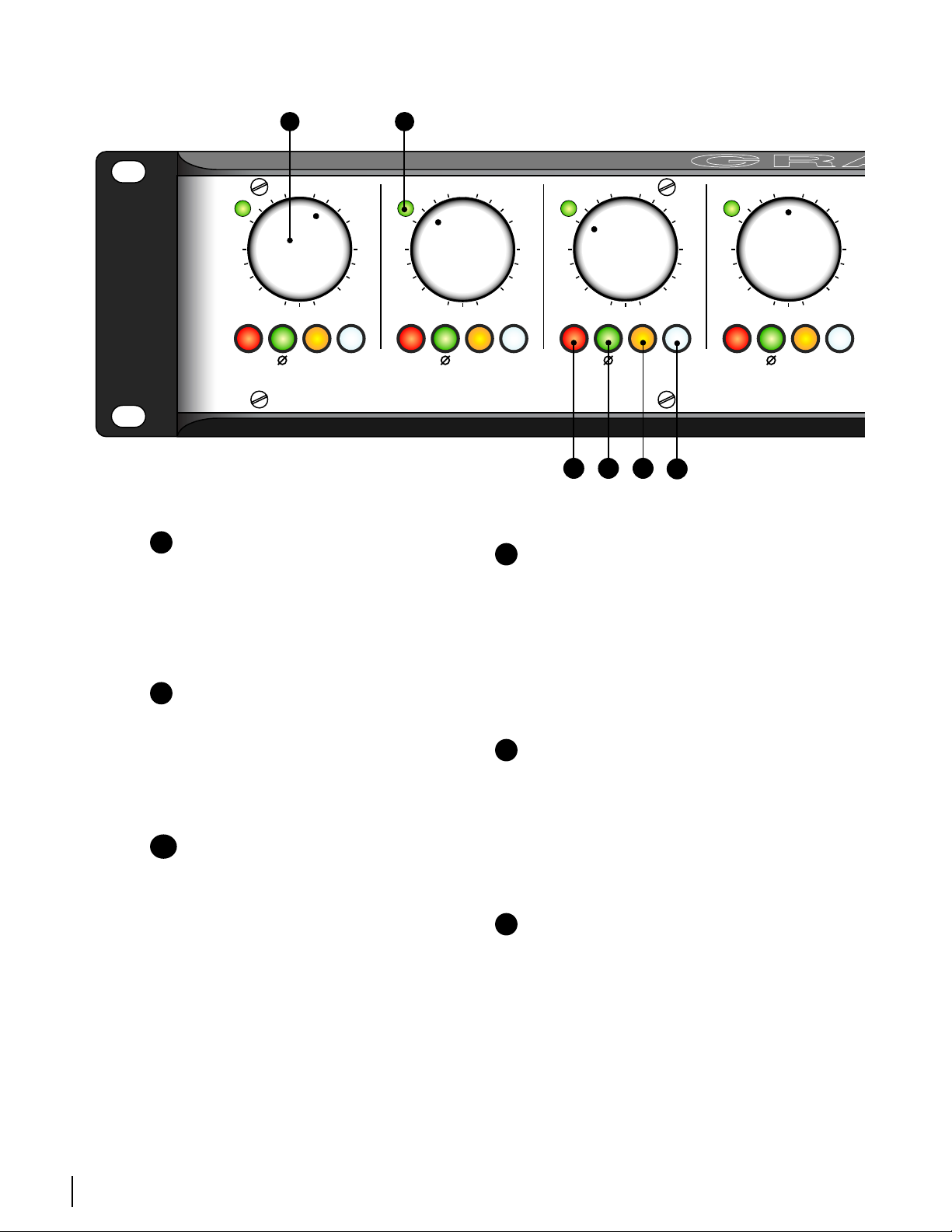
FRONT PANEL CONTROLS
A
A
24 pOSITION GOLd CONTACT GAIN SwITCh
Each gain control has 24 positions and adjusts the
voltage gain from 18dB to 64dB in 2dB steps. For
reference, the 9 o’clock position is 28dB, the 12
o’clock position is 40dB, and the 3 o’clock position
is 52dB.
B
C
D
phASE REVERSAL SwITCh
E
D
F
The phase reverse switch reverses the absolute
polarity of the music signal at the input of the
preamplifier. The switch illuminates green and
provides power for a sealed gold contact relay located on the preamplifier circuit board. This elimi-
B
BI-COLOR LEd pEAK INdICATOR
The LED peak indicator, which monitors the output
signal, turns green at -14dB and switches to red at
+16dB (12dB before clipping). The threshold level
for peak indication is adjustable on each channel
(see page 8).
nates signal wiring to the front panel and switch
contact performance problems.
E
-20 pAd SwITCh
The 20dB attenuator switch attenuates the input
signal 20dB. The switch illuminates amber when
engaged. Like the phase reverse switch, this switch
C
48V phANTOM pOwER SwITCh
The phantom power switch (labeled +48V) connects the +48V power supply to pins 2 and 3 on
the XLR input connector. This switch illuminates
red. It should be noted that the LED in this switch
actually monitors the voltage at the input. With no
microphone connected, the LED will continue to
illuminate for approximately 10 seconds after the
phantom power is turned off as the filter capacitors discharge. As well, even if the phantom power
controls a sealed gold contact relay on the preamplifier circuit board. With the -20 switch engaged,
the effective gain range becomes -2dB to 44dB.
F
RIBBON MIC MOdE SwITCh
This switch activates a 10dB increase in overall
preamplifier gain while simultaneously disabling
the 48V phantom power circuit to protect ribbon
microphones. As well, the input coupling capaci-
tors are bypassed.
is switched off, the LED will illuminate if voltage is
being fed from an external source. (i.e. when using
a direct split in a remote recording application.)
grace design m801
4
owner’s manual
 Loading...