

Page 1
Light Bar 5
(for 5-foot frames)
Assembly Instrucons
05/01/19
Page 2

Parts List - Light Bar 5
PART # DESCRIPTION QTY
HG01100-601 CURVED LEG-LIGHT BAR 4
HG01100-602 CLAMP PLATE-LIGHT BAR 4
HG01100-603 VERTICAL LEG BOTTOM-LIGHT BAR 2
HG01100-604 CORNER CONNECTOR-LIGHT BAR 2
HG01100-612 5-FOOT ANGLED CONNECTOR-LIGHT BAR 1
HG-01100-606 VERTICAL LEG-TOP-LIGHT BAR 2
HG01100-607 TOP TUBE-LIGHT BAR 2
HG01100-101 SCREW-M6 X 50 SKB ZN 12
HG01100-100 NUT-M6 LOCKNUT CLASS 8 12
QF09318-07 SCREW-M8 X 1.25 X 16 SBHCS 20
HG01100-609 END PLUG-LIGHT BAR 8
HG01100-610 BUMPER FOOT-LIGHT BAR 4
QM10289 HEX KEY L 5MM 1
QM10288 HEX KEY L 4MM 1
QF09318-12 WRENCH-POLE ASSEMBLY (10MM) 1
HG01100-605 STRAIGHT CONNECTOR-LIGHT BAR 2
HG01101-100 BATTEN LED LIGHT-LIGHT BAR 2
HG01101-101 CLIP-LIGHT BAR SHADE 4
HG01101-102 SHADE-LIGHT BAR 4
HG01101-103 POWER CORD-LIGHT BAR 1
HG01101-104 INTERCONNECT CORD-LIGHT BAR 1
HG01101-105 POWER SOCKET COVER-LIGHT BAR 1
QM10885 SCREW-M4 X10 PHP ZN 4
HG01101-107 SHORT LOOP VELCRO-LIGHT BAR 8
HG01101-108 LONG HOOK VELCRO-LIGHT BAR 8
HG01101-106 CLIP-POWER CORD U TYPE 6
HG01200-205 INSTRUCTIONS: 10-FOOT LIGHT BAR AND 2-FOOT LIGHT BAR KIT 1
Width Notes:
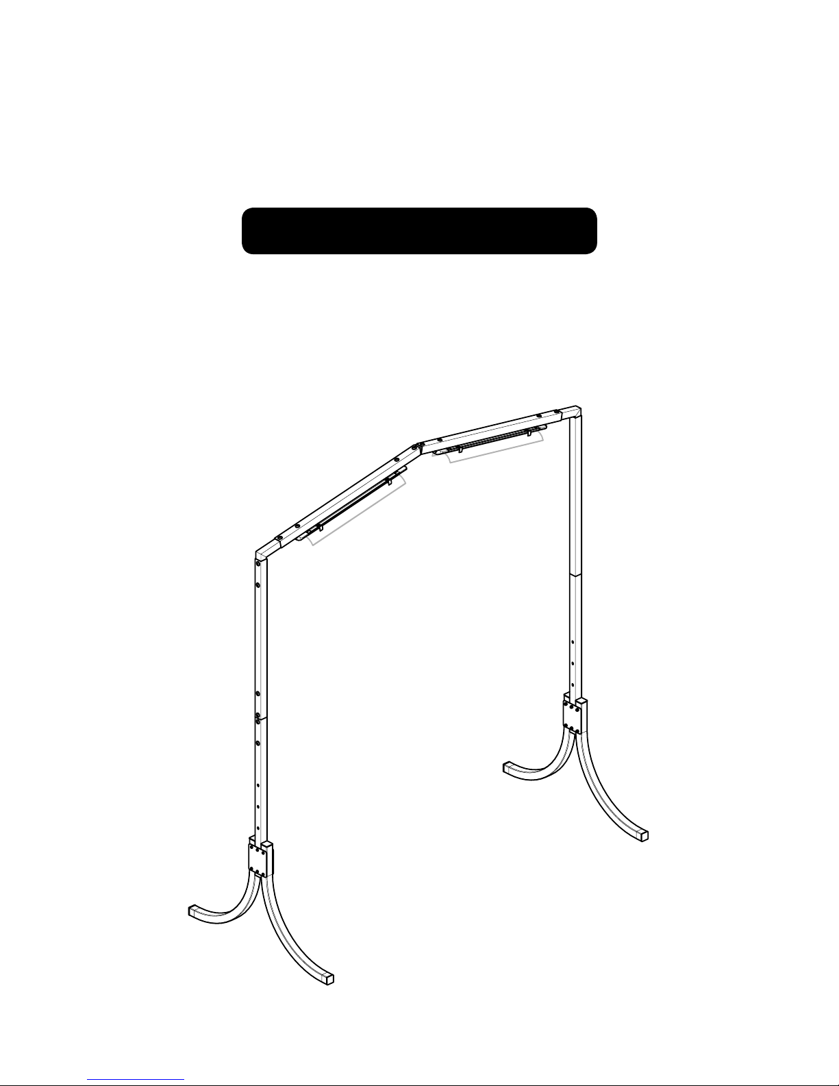
• The Light Bar 5 is approximately 72.5 inches wide, outside to outside.
• The inside to inside measurement is about 4 inches narrower than the outside to outside measurement listed
above, due to leg tubing, clamp plates and hardware.
 IMPORTANT NOTE: The Light Bar 2 Extension, used to extend an 8/10 foot Light Bar to 12-foot or
14-foot, is not compable with the Light Bar 5. The Light Bar 2 Extension cannot be added to the Light
Bar 5 to make a 7-foot Light Bar.
Light Bar 5 Assembly InstruconsPage 2
Page 3
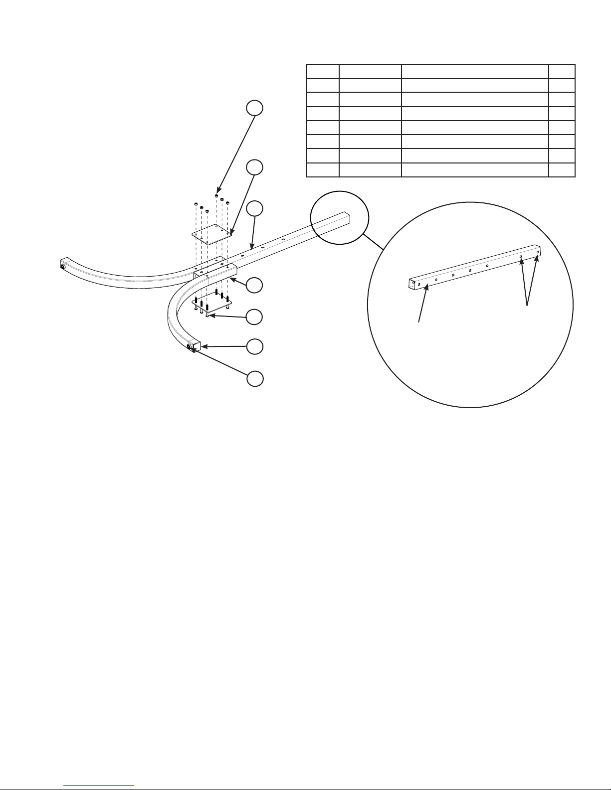
Secon 1: Lower Leg Assembly
1
2
3
4
ITEM PART # DESCRIPTION QTY
1 HG01100-100 NUT, M6 LOCKNUT CLASS 8 12
2 HG01100-602 CLAMP PLATE, LIGHT BAR 4
3 HG01100-603 VERTICAL LEG BOTTOM, LIGHT BAR 2
4 HG01100-601 CURVED LEG, LIGHT BAR 4
5 HG01100-101 SCREW, M6 X 50 SKB ZN 12
6 HG01100-609 END PLUG-LIGHT BAR (pre-assembled) 8
7 HG01100-610 BUMPER FOOT-LIGHT BAR (pre-assembled) 4
5
6
7
NOTE: The light bar has four height
sengs. The image above shows the
light bar in its highest seng. The highest
seng is approximately 81 inches high
from the center top of the light bar to
the oor; the other sengs are about
77 inches, 73 inches and 69 inches at
the lowest seng.
Step 1: Place six screws (item 5) through a clamp
plate (item 2). Place the plate on a work
surface such as a table or oor, with the
screws poinng up (as shown).
Step 2: Place one vercal leg boom (item 3)
over the center two screws in the plate
as shown.
NOTE: The screws go all the way through
the leg parts.
These two holes do
Place this side down
against the work surface for
assembly, as shown in the
rst diagram at the le.
not go all the way
through the leg.
Step 4: Place one curved leg (item 4) over the
two le screws in the plate as shown.
Step 5: Place one clamp plate over the legs
and screws.
Step 6: Start a locknut (item 1) onto each screw.
Step 7: Orient the leg to access the screw heads
and lock-nuts.
Step 8: Push the two curved legs ght against
the vercal leg boom, hold the lock
nut with the 10mm wrench provided. To
help prevent paint damage, ghten the
screws rmly using the 4mm hex tool
while holding the 10mm wrench rmly
in place.
Step 3: Place one curved leg (item 4) over the
two right screws in the plate as shown.
Step 9: Repeat steps 1-7 to make a second lower
leg assembly.
Page 3Light Bar 5 Assembly Instrucons
Page 4

Secon 2: Upper Leg to Lower Leg Assembly
1
2
3
ITEM PART # DESCRIPTION QTY
1 HG01100-604 CORNER CONNECTOR-LIGHT BAR 2
2 QF09318-07 SCREW, M8 X 1.25 X 16 SKBHCS 12
3 HG01100-606 VERTICAL LEG TOP-LIGHT BAR 2
4 HG01100-605 STRAIGHT CONNECTOR-LIGHT BAR 2
Step 1: Place a corner connector (item 1) into an
vercal leg top (item 3).
NOTE: The corner has a long and short
end. The long end will go into the top bar;
the short end goes down into the vercal
leg top piece.
Step 2: Insert two screws (item 2) through the
vercal leg and into the corner connector.
4
Step 3: Place a straight connector (item 4) into the
boom of the vercal leg top.
Step 4: Insert two screws (item 2) through the leg
into the straight connector.
Step 5: Slide the top leg assembly down over the
boom leg assembly.
Step 6: Insert two screws (item 2) through the
boom leg assembly into the straight
connector.
Step 7: Using the provided 5mm hex tool, ghten
the six screws rmly.
Step 8: Repeat steps 1-7 to make another
leg assembly.
Light Bar 5 Assembly InstruconsPage 4
Page 5

Secon 3: Top Bar Assembly
3
2
ITEM PART # DESCRIPTION QTY
1 HG01100-607 TOP TUBE-LIGHT BAR 2
2 QF09318-07 SCREW, M8 X 1.25 X 16 SKBHCS 4
3 HG01100-612 5-FOOT ANGLED CONNECTOR-LIGHT BAR 1
1
Step 1: Place a 5-foot angled connector (item 3)
between two top tubes (item 1).
Step 2: Insert four screws (item 2) through the
top tubes into the angled connectors.
Step 3: Tighten all four screws rmly with the
5mm hex tool.
Page 5Light Bar 5 Assembly Instrucons
Page 6

Secon 4: Legs to Top Bar Assembly
ITEM PART # DESCRIPTION QTY
1 QF09318-07 SCREW, M8 X 1.25 X 16 SKBHCS 4
1
Step 1: Lay the two leg assemblies and the top
tube assemblies on the oor as shown.
Step 2: Slide the corner connectors into the top
bar assembly.
Step 3: Insert the screws through the top bar
assembly into the corner connectors
and ghten rmly with the 5mm hex
tool provided.
Light Bar 5 Assembly InstruconsPage 6
Page 7

Secon 5: Light Assemblies to Top Bar Assembly
ITEM PART # DESCRIPTION QTY
1 QM10885 SCREW, M4 X 10 PHP ZN 4
2 HG01101-101 CLIP-LIGHT BAR SHADE 4
3 HG01101-100 BATTEN LED LIGHT 600MM 2
4 HG01101-104 INTERCONNECT CABLE 1
1
2
3
Step 1: Stand the frame upright onto its feet.
Step 2: Insert a Phillips head screw (item 2)
through the clip as shown and ghten
with a #2 Phillips screwdriver (not provided) so that the clip is perpendicular to the
top tube. Repeat for the other clips.
Step 3: Snap each of the LED lights into the clips
so they are approximately centered.
NOTE: It is important that the LED lights
4
not be too far apart. The interconnect
cords should have a lile tension pushing
them into the connector, otherwise they
will pull out of the LED light assembly.
Step 4: Plug the interconnect cable between
the two LED light assemblies.
Page 7Light Bar 5 Assembly Instrucons
Page 8

Secon 6: Light Shade Assembly
ITEM PART # DESCRIPTION QTY
1 HG01101-102 SHADE-LIGHT BAR 4
2 HG01101-107 SHORT LOOP VELCRO™-LIGHT BAR 8
3 HG01101-108 LONG HOOK VELCRO™-LIGHT BAR 8
Place short loop Velcro™ here
Place large hook Velcro™ here on the boom of the
light shade on both ends. Align the Velcro™ le to
right to match the clips with the short loop Velcro™.
Step 1: Remove the backing from a short loop
Velcro™ and place on the clip as shown.
Each clip has two pieces of short loop
Velcro™.
Step 2: Repeat step 1 on each side of all clips.
Step 3: Lightly mark with a pencil on the under
side of the light shade where the long hook
Velcro™ will go. It needs to align with the
short loop Velcro™ on the clips.
Step 4: Remove the backing from the long hook
Velcro™ and place it on the underside of
the light shade on each end.
Step 5: Repeat step 4 for each light shade.
Light Bar 5 Assembly InstruconsPage 8
Page 9

Secon 7: Power Cord and Clips
1
Place the power socket
cover onto the last unused
power socket.
ITEM PART # DESCRIPTION QTY
1 HG01101-105 POWER SOCKET COVER-LIGHT BAR 1
2 HG01101-106 CLIP-POWER CORD U TYPE 6
3 HG01101-103 POWER CORD-LIGHT BAR 1
2
3
Place power cord clips (U type) at these locaons:
Step 1: Note the locaons for the power cord
clips (U-type).
Step 2: Remove the clip backing and press the
clips rmly onto the frame at each
locaon shown above.
Step 3: Insert the cord into the tabs.
NOTE: It may be easier to insert the cord
into the clips by spreading the two tabs
a bit apart rst, using a tool such as a
screwdriver.
Step 4: Place the power socket cover (item 3) in
the last unused socket. This will prevent
someone from inadvertently placing
anything into the socket.
Page 9Light Bar 5 Assembly Instrucons
 Loading...