

Page 1
User’s Guide
____________________________________________
Mini-Bullet s II
Wireless 900MHz Speaker System
Mini-Bullets II 900MHz Wireless Speaker System
Model: GDI-AQBLT300 /AQBLT31
Page 2

IMPORTANT: Please read your User’s Guide before using your system
INTRODUCTION
Your MINI-BULLETS II speaker is designed using the latest wireless technology to
enjoy audio anywhere inside or outside your home. Simply connect the desired
audio source (Radio, TV, VCR, Hi-Fi and CD/MP3/VCD/DVD player) to the speaker
transmitter.
IMPORTANT SAFETY INSTRUCTIONS
1. Read & keep these instructions.
2. Keep these instructions.
3. Follow all warnings and cautions
4. Do not use this apparatus near water.
5. Do not install near any heat source such as radiators, heat registers, stoves, or
other apparatus (including amplifiers) that produce heat.
6. Do not open the cabinet as this might result in damage to the circuitry o r electrical
shock. If a foreign object should get into the set, contact your dealer.
WARNING
POWER ADAPTOR: The power adaptor included with your unit is intended for
indoor environments and use. Do NOT
use the power adapter in moist or wet
environments. Where there is a chance of rain, you may operate the speaker
with battery power. NEVER
body of water. Use batteries power only when used in water
CAUTION
RISK of ELECTRIC SHOCK – do NOT open! Do NOT remove casing. No user
serviceable parts inside. Refer servicing to qualified service personnel.
WARNING
This product may contain chemicals listed in Proposition
65
http://www.oehha.ca.gov/prop65/prop65_list/Newlist.html that may be
known to cause cancer, birth defects or other reproductive harm
use the adaptor with your Speakers in any type of
P.1
Page 3
FEATURES
1. Automatic PLL (Phases Lock Loop) scanning system on speaker receivers.
2. PLL (Phase Lock Loop) transmitter transmission system.
3. 900 MHz RF (Radio Frequency) technology
4. Weather-proof style for outdoor / indoor speaker system use
5. RF technology lets you place the rock speaker freely anywhere in your garden
6. Operate up to 150 feet
7. No line of sight limitation
8. Auto ON/OFF control on transmitter
9. Auto tuning function on the speaker
10. Optional transmitter AC power adaptor or battery operation for portability
11. Universal Transmitter can be used with Aqua Sounder II, Schooner II & Rock
Sounder Speakers for ‘unlimited expandability’.
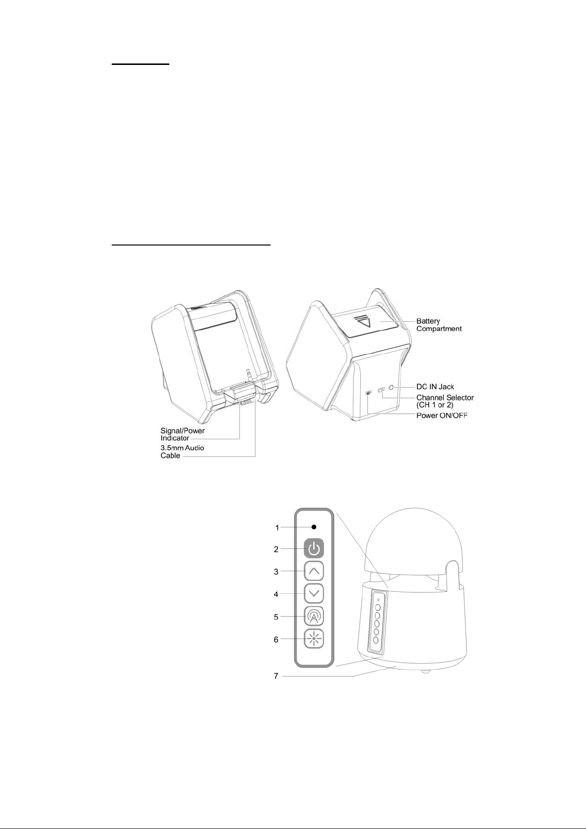
COMPONENT IDENTIFICATION
TRANSMITTER
PEAKER (RECEIVER)
S
. Indicator LED
1
2. Power ON/OFF
3. Volume UP
4. Volume Down
5. Auto Tune
6. Mood Light
7. Battery Comp
artment
P.2
Page 4

1. Batteries Compartment 3. Handle 5. Volume Up 7. Power
ck n 2. DC IN (power adapter) Ja 4. Auto Tune 6. Volume Dow ON/OFF
SET UP
TRANSMITTER
1. onnect the AC power adaptor included with your unit to electrical wall outlet.
C
2. lug the AC power adaptor included with your unit in the jack located on theP
rear of the transmitter. Option 4 X “AA” size ALKALINE batteries can be used
to power the transmitter for portability. NOTE: ensure battery polarity (+/-) are
matched and correctly aligned correct when inserting the batteries in the
compartment
3. nsmitter by setting the POWER switch to the ON position, and
urn on the traT
the POWER LED (blue) on transmitter will start flashing.
4. tter can be connected
he retractable audio cord located at the front of transmiT
to an audio output jack of any audio source (i-Pod, i-Phone, MP3, Hi-Fi,
MP3/CD/VCD/DVD players, etc.)
5. When the transmitter receives an audio signal, the blue SIGNAL LED and the
P.3
Page 5

red POWER LED will illuminate together. If the blue SIGNAL LED does not
illuminate, ensure the audio source is turned on and properly connected to the
jack.
SPEAKER (RECEIVER)
1. Connect the 12
each speaker, then plug into the power wall outlet. You may also insert 6 x ‘AA’
size ALKALINE batteries into the battery compartment. Ensure the batteries
polarity (+/-) are correct, at the bottom of the speakers
(batteries not included in the package).
V power adaptor to the DC input jack on the bottom of
2. Press the POWER button and turn the speakers ON. The POWER LED
w
ill light up in blue. Switch off the speakers by pressing the POWER
button on the speaker, and the LED will turn off.
PERATION
O
. Turn on the audio source to which the transmitter is connected with.
1
2. Turn on the transmitter by set the POWER switch to ON position
POWER LED on transmitter will light up .
3. Select between the channels on the tran ance for the
location selected.
smitter for best perform
, and the
4. Press the “POWER” button on the speaker to turn on the speaker Press the
“SCAN” AUTO-TUNE button to get the best tuning reception on the speaker.
P.4
Page 6

When the button is pressed, frequency tuning starts automatically and it stops
when a signal is detected. The POWER LED will illuminate steadily once
connected.
Î Keep a distance of the speaker up to 7 meters apart from
transmitter, and then press “SCAN” AUTO TUNE button for best
tuning reception.
Î You should now be
without disruption. Should you experience a “frequency jam”, adjust the
channels by switch from one channel to the other channel on the transmitter ,
and then press the “SCAN” AUTO TUNE button on the speaker again.
able to place the speakers freely from room to room
OTE: The signal fr
increased distances and as barriers and interference increase.
5. Adjust d up by
OTE: N
NOT
storage periods. Move speakers indoors when weather conditions are extreme.
6. Outdoor, Water Use & Weather Conditions
WARNING: The power adaptor included
e
nvironments and use. Do NOT
environments. Where there is a chance of rain, you may operate the speaker with
battery power.
the volume to the desired listening level. Volume can be adjuste
pressing “+” button or down by pressing the button “-“ to the desired listening
level
IF disruption should occur (signal breaks up), press the “SCAN”
auto-tuning button on the speaker to maximize best reception.
u hear interference from other devices, switch between the chan
IF yo nels on
the transmitter and press the “SCAN” auto-tuning button for best reception.
E: batteries should be removed from the transmitter & speakers for extended
Î Mini-Bullets II speaker is designed to
conditions
Î The speaker
Î The transmitter and adapters must NOT be used in any type
or in a moist or wet environment.
TROUBLE SHOOTING
NO SOUND
- Check tha
Check there is not too much water retention inside the speaker grill. Turn
-
over the speaker and let the water drain out from the spe
- Ensure the AC/DC adaptor is fully inserted into the AC outlet and the powe
connection input on the transmitter.
t the batteries are fully charges on the speaker
om the transmitter will decrease in strength over N
be used in conservative outdoor
should not be operated in extreme temperature
of water body
with your unit is intended for indoor
use the power adapter in moist or wet
aker grill.
r
P.5
Page 7

- Ensure the speaker is switch ON.
- Speaker’s battery capacity is low, connect the AC/DC adaptor to the speaker.
- Ensure the TV or audio component
- The volume of speaker is too low, adjust the volume to an appropriate level.
DISTORTED SOUND
Press the “AUTO-TUNE Check there is not Too much water retention inside the speaker grill. Turn
-
over the speaker and let the water drain out from the speaker grill.
- Change the position of the channel selector on the transmitter. Press “AUT
TUNE” button on the speaker.
- Ensure the volume level of speaker is adjusted properly.
- The speaker is too far away from
- Audio input level of the audio signal is too low. Turn up the
- The Transmitters audio input level is too high, lower the audio source volume l
- Ideally the audio source is ON and volume level is set to at 50-75% of maximum.
” button on the speakers to find the transmitter frequency
is ON.
O
the transmitter, m ove it close r.
audio source volume
evel
SPECIFICATIONS
Transmission Mode : UHF stereo
Carrier Frequency : 900 MHz
Operation Voltage : Transmitte
included) or DC 12V 200mA
line batteries (not
Frequency Response :
Distortion : 1.0%
S/N Ratio : 65dB (
Channel S : 50dB (Typical)
Operation Distance : Up to 150 feet
Output Power : 2 x 4W (RMS)
WARNING: es r modifications to this unit no
This device mu in the package.
eparation
Chang o t expressly approved by the
party responsible for compliance could void the user’s authority to
operate the equipment. Operation is subject to the following two
conditions: (1) this device may not cause interference, and (2) this
device must accept any interference, including interference that
may cause undesired operation of the device.
st be used with the AC/DC adaptor supplied
Speaker, 6 X ‘AA’ size Alka
included) or DC 12V 1.2A adaptor
40Hz – 12KHz
CUSTOMER SERVICE & SUPPORT
r, 4 X ‘AA’ sixe Alkaline batteries (not
typical)
y other Grace Digital For questions regarding your system or an product,visit us at:
www.gracedigitalaudio.com
or contact us at: info@gracedigitalaudio.com
04_2010
P.6
Page 8

P.7
 Loading...