

Grace 901 Owner's Manual
Model 901
HEADPHONE AMPLIFIER
OWNERS MANUAL
PO Box 204 Boulder, CO 80306
tel: 303.443.7454 fax: 303.444.4634
email: info@gracedesign.com web: www.gracedesign.com
Revision A November, 2001 © Copyright 2001, Lunatec LLC

Thank you for purchasing the Model 901 headphone amplifier. It is
designed to be completely reliable and easy to use. However, we as k that you
take the time to familiarize yourself with some of the more important operation
instructions in this manual to avoid most common user problems.
The Model 901 amplifier is an ultra high fidelity monitoring device. By
revealing all of the contents of your signal, we hope it helps you achieve a new
level of excellence in your audio recordings.
Feel free to check out our internet web page for the latest information
regarding your amplifier. You can always find the latest owners manuals and
other technical documents at:
http://www.gracedesign.com/documents/docs.html
MODEL 901 FEATURES
• Balanced XLR analog inputs
• Unbalanced RCA analog inputs
• AES, SPDIF and TOS LINK digital inputs
• High current output amplifier drives 8 Ohm loads
• 24 position level attenuator with .05dB channel matching
• Internal linear power supply
• High current, low noise torroidal power transformer
• No electrolytic capacitors in the signal path
• Highest quality metal film resistors
• Ultra low distortion 24 bit DAC accepts sample rates up to 96kHz
• Automatic digital de-emphasis filter
• 10dB gain boost switch for -10 sources
• Fast, musical transipedance output amplifiers
• Precision instrumentation balanced input amplifiers
• Sealed gold contact relays for input select and gain boost switching
1
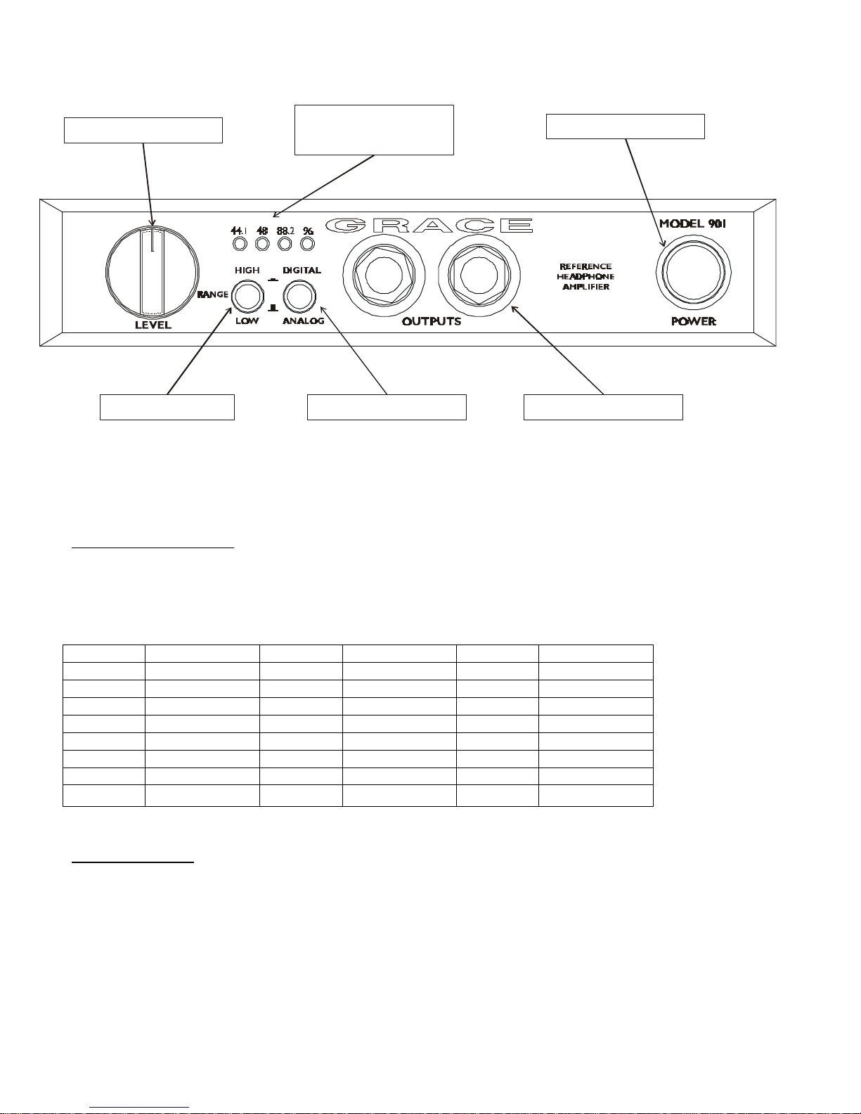
LEVEL CONTROL
INDICATOR
GAIN RANGE INPUT SELECT OUTPUT JACK
SAMPLE RATE
FRONT PANEL CONTROLS
POWER SWITCH
LEVEL CONTROL The 901 level control is assembled with an ultra precision
24 position gold contact switch. Using low inductance surface mount metal
film resistors this switch is the ultimate attenuator for sonic fidelity and level
accuracy. Left-right channel balance is maintained to within 0.05dB at any
setting. The attenuation curve is shown in the table below.
POSITION ATTENUATION POSITION ATTENUATION POSITION ATTENUATION
24 0 16 -16 8 -32
23 -2 15 -18 7 -34
22 -4 14 -20 6 -38
21 -6 13 -22 5 -42
20 -8 12 -24 4 -46
19 -10 11 -26 3 -50
18 -12 10 -28 2 -60
17 -14 9 -30 1
-∞
GAIN RANGE The gain range switch provides an extra 10dB of gain for
monitoring –10dB signals or use with low sensitivity headphones. With the
LEVEL CONTROL at maximum, the LOW gain position provides +10dB overall
gain when using the analog inputs. When using the digital input, this setting
will yield +20dBu out at 0dBFS. When the GAIN RANGE switch is depressed
the overall gain is +20dB
2
 Loading...