

Page 1

OWNERS MANUAL
MODEL 801R
REMOTE CONTROL
MICROPHONE PREAMPLIFIER
PO Box 204 Boulder, CO 80306 303.443.7454 fax: 303.444.4634
http://www.gracedesign.com
Revision Ax January, 2000
© Copyright 2000, Lunatec LLC
1
Page 2
Overview
The 801R system consists of an 8 channel preamplifier chassis, a power supply chassis
and an optional RCU . The preamplifier chassis contains 8 audio amplifier PCBs, a
micro controller PCB and a front panel LCD display. The preamplifier chassis is
equipped with two Phillips I2C Bus connectors (D-sub 9 pin) and MIDI IN and OUT
connectors. The RCU contains identical micro controller and display PCBs and has a
single Phillips I2C Bus connector.
The preamplifier can be controlled by the RCU, via MIDI, or directly from its front panel.
The RCU connects to the preamplifier via I2C which provides a bi-directional data link.
Please Note: The 9pin I2C is a proprietary interface. It is not compatible with RS232, RS-422, or any other 9 pin based serial protocol found in the recording studio
environment. Do not connect your Grace Design 801R or remote unit to any other
equipment!
The RCU can control more than one preamplifier. By connecting the remote unit to one
preamplifier and then connecting the remaining preamplifier units together with I2C
cables in a daisy chain fashion up to 8 preamplifiers can be connected together in a
system.
Grace Design 801R Remote Control Preamplifier
Preliminary user information
Operation
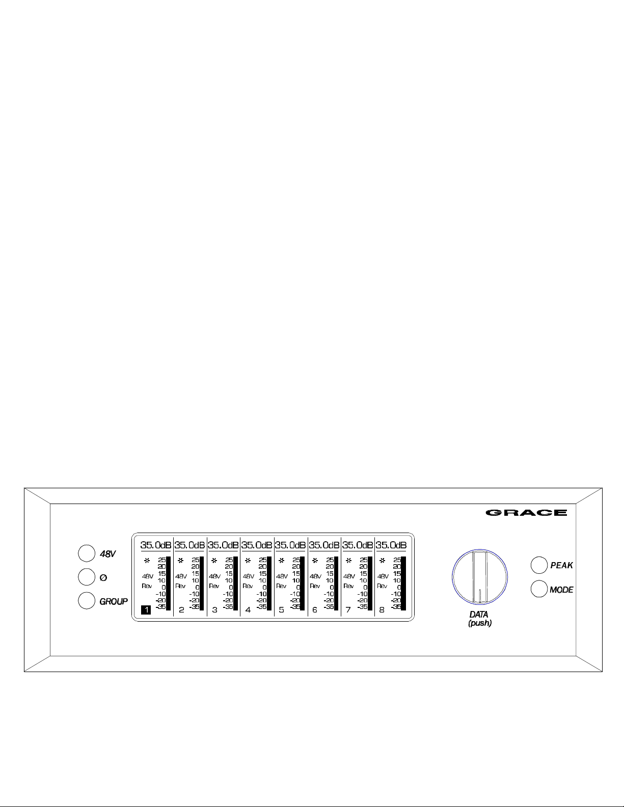
Front Panel Controls
Figure 1. RCU front panel
2
Page 3

The front panels of the RCU and the 801R preamplifier are identical and consist of the
following controls and indicators:
+48 Volt phantom power push-button
PHASE reverse push-button
GROUP push-button
PEAK Indicator Reset push-button
DATA Variable function rotary encoder with push-button
MODE select push-button
LCD display 64x240 pixels
Preamplifier Modes
Channel mode: This is the default power on mode. In Channel mode the rotary encoder
is used to select one of the eight visible channels for adjustment. When selected, the
settings for a channel can be adjusted with the +48, PHASE, or DATA controls. Pushing
the +48V or PHASE button toggles that function on or off on that channel. Pushing the
DATA control enters the Gain Adjust mode. While in Gain Adjust Mode the Gain
numeric display characters are highlighted and the rotary encoder adjusts the gain up or
down. Pushing the DATA control again exits the Gain Adjust mode and returns to the
Channel select mode. The bar graph meter at the right edge of each channel section is
a 15 segment peak meter that indicates preamplifier output levels from –35dBu to
+25dBu. Unlike the typical log scale level meter in a tape recorder, the 801R meter
represents level in a mostly linear dB scale. This allows for a meter range of 60dB and
useful peak output level information up to 4dB of the output clip point.
Note: You will notice that the meter ballistics will at first seem sluggish but this setup
actually provides more useful information about your peak levels and headroom status.
Meter Mode: In Meter mode the LCD displays bargraph level meters for up to 24
channels at a time. The DATA control is used to highlight an individual channel. If there
are more than 24 channels present in the system then the display “scroll” as the DATA
control is rotated. Pushing the DATA control when a given channel is highlighted
“zooms” to the Channel mode for channel parameter adjustment. Note: Meter Mode is
available on the RCU only and can only be accessed if more than one preamplifier are
connected to the system.
Setup Mode: The Setup mode displays a series of menus for various user setup options.
Step through the various setup screens by pushing the MODE pushbutton.
The Preamplifier ID: This field allows one to select a unique identification for each
preamplifier in a system. The ID number also assigns channel numbers to the
preamplifier. For instance, ID 1 includes channels 1-8, ID 2 includes channels 9-16
and so on to ID 8 which includes channels 57-64. Pushing the DATA knob once
allows the ID number field to changed by rotating the DATA knob. Pushing the DATA
3
Page 4

knob again saves the setting. It is very important that all preamplifiers in a multiple
preamplifier system have unique ID numbers.
Peak Threshold: Each preamplifier maintains a history of peak events. A peak event
is defined as a moment where the audio level on a preamplifier channel exceeds a
user adjustable reference level. If a channel has experienced a peak above reference
level then the “Peak” character appears next to the appropriate channel in the Display.
Pushing the PEAK button resets all Peak History values on the channels being
displayed. The Peak Threshold can be adjusted by pushing the DATA knob once and
then turning the DATA knob until the desired level is visible. Pushing the DATA knob
again saves the setting.
Peak Hold: Various decay times can be chosen for the peak indicator. These include
1, 3, 10 second and infinite hold times.
Presets: The settings for each channel in a preamplifier can be manually stored for
later recall in one of 10 user pre-set registers. Registers 1 through 10 are available for
user storage.
Display contrast: The display contrast can be adjusted to optimize the display for
various viewing angles.
Back light control: The LCD display back light illumination can be turned off if desired.
GROUP MODE: The group mode allows two to eight adjacent channels to be grouped
together for gain change operations. This can be very convenient when using stereo
pairs or groups of microphones on one instrument. To enter group mode push the
GROUP pushbutton. The words “Group Mode Active” will appear just below the gain
status characters. To define a group, place the cursor on the left most channel of the
channels to be grouped and turn the DATA knob clockwise while pressing the GROUP
pushbutton. You will notice that the vertical dividing lines between channels disappear
as channels are added to a group. Once in Group mode, gain changes are made in the
same manner as in normal Channel select mode. To remove a group place the cursor
on the right most channel of the channels in the group and turn the DATA knob counter
clockwise while holding the GROUP pushbutton. You will notice that the vertical dividing
lines between channels reappear as channels are removed from a group.
INSTALLATION
PREAMPLIFIER POWER CONNECTIONS
An 8' (2.8m) DC power cord is supplied to connect the power supply unit to the
preamplifier unit. This cord can be identified by the 9 pin circular connectors at each
end.
Please note that the DC power cord should be connected before the AC power is turned
on. This prevents incorrect power sequencing which can cause damage to the audio
circuits.
To avoid any interference with the low level audio circuitry, the power supply should be
located at least 3' (1m) from the preamplifier unit.
4
Page 5

A standard AC power cable is included. For safety, it is recommended that the cord be
connected to a grounded outlet. In the event of noise from a ground loop, the audio
ground can be isolated from the chassis ground by removing jumper J9 in the power
supply. (See paragraph 6)
AC input voltage settings can be adjusted for 100V, 120V, 220V and 240V operation at
50-60Hz. From the rear of the power supply unit, open the trap door next to the IEC
power inlet with a small screwdriver. Carefully pull the voltage select cam straight out
and then insert with the desired voltage showing. Do not try to rotate the cam while it is
in the power input module. Replace the fuses with the proper value selected from the
table below. Be sure to use a GMC type time delay or fuse with a 250V rating.
Voltage 100V 120V 220V 240V
Fuse rating 0.75A 0.75A 0.5A 0.5A
Figure 4. Fuse value table
Grounding options
In certain installations, it may be desirable to separate the preamplifier signal ground
from the power supply chassis and earth grounds. Noise inducing ground loops can
be broken while retaining the safety feature of the grounded AC power cord. The
801R should not be operated with a ground lift or "cheater" plug on the AC power
cord. Simply set the AUDIO GND toggle switch on the rear panel of the power supply
unit to the desired setting (ISO or EARTH).
REMOTE UNIT POWER CONNECTION
The RCU is powered with the supplied AC wall adapter. It is recommended that the I2C
data connections be made before applying power to the RCU. Simply plugging the
2.1mm barrel connector into the DC power jack turns the power on. The AC wall adapter
is rated for 7.5V / 1A DC. (+) is in the center and (–) is on the outside sleeve.
AUDIO CONNECTIONS
Input connections are made via female XLR connectors with pin 2 positive, pin 3
negative and pin 1 ground. 48V phantom power is supplied on pins 2 and 3.
Output connections are made via male XLR connectors with pin 2 positive, pin 3 negative
and pin 1 ground. An additional set of parallel outputs is provided with a 25 pin D-sub
connector. Both sets of output connectors can be used simultaneously.
If the output is to be used unbalanced, pin 1 should be connected to signal ground and
pin 2 to signal hot. Due to the nature of the balanced output stage, pin 3 should be left
open for unbalanced operation. See figure below. Note: This will provide a signal of
positive absolute polarity when the preamplifier is being used with a microphone which
produces a positive voltage on pin 2 with positive air pressure on the front of the
diaphragm. While a vast majority of microphones conform to this standard a few do not.
Use the phase reverse switch to compensate if necessary.
5
Page 6

SHIELD
HOT
1
3
Figure 2. Unbalanced output cable termination
Figure 3. 25 pin D-sub output connector
2
XLR FEMALE
DATA CONNECTIONS
RCU to Preamplifier data connections are made with an I2C serial cable. This cable has
a male 9 pin D-sub connector at each end. The data cable can be supplied by the
factory in any length up to 1000’ The I2C cable should be connected to the 9 pin D-sub
connector on the remote unit and to the I2C IN 9 pin D-sub connector on the preamplifier.
As well, the RCU is supplied with a set of adapters that allow one to use a standard
microphone cable for the serial data link. The microphone cable can be up to 1000’ long.
It is not recommended to use a microphone line in a multi-channel snake for this
application because the serial data activity can induce noise into adjacent audio signal
lines.
Preamplifier to Preamplifier connections are made by connecting a 9 pin I2C cable from
the I2C OUT connector on one preamplifier to the I2C IN connector on another
preamplifier.
6
Page 7

SPECIFICATIONS
PREAMPLIFIER SPECIFICATIONS
FREQUENCY RESPONSE
@ 40.5dB gain ± 0.2dB 50Ω source 15Hz-300KHz
@ 40.5dB gain ± 3dB 50Ω source 4.5Hz-1.0MHz
THD+N
@ 20dB gain +20dBu out <.0010%
@ 40.5dB gain +20dBu out <.0010%
@ 60.0dB gain +20dBu out <.0050%
INTERMODULATION DISTORTION
@40dB gain +25dBu out
SMPTE/DIN 1:1 (50Hz, 7kHz) <.0020%
SMPTE/DIN 4:1 (50Hz, 7kHz) <.0040%
NOISE - REFERRED TO INPUT
@60dB gain 50Ω source -130dB
@60dB gain 150Ω source -128dB
@60dB gain 600Ω source -124dB
PHASE DEVIATION
50-20KHz <4°
CROSSTALK
Any Channel @40.5dB gain 1kHz -100dB
CMRR
@60dB gain, 3.5Vcm, 1KHz >70dB
@60dB gain, 3.5Vcm, 10KHz >70dB
Output CMRR >60dB
PHANTOM POWER
Voltage +48V +0.9/ -0.0
6.8kΩ resistor match tolerance +/- 0.01%
MAXIMUM OUTPUT LEVEL
Balanced +28dBu
Unbalanced +22dBu
IMPEDANCE
Input 1600Ω
Output 50Ω
Minimum Load Impedance 50Ω
WEIGHT 12lbs
DIMENSIONS 2U rack mount x 10” deep
7
Page 8

POWER SUPPLY SPECIFICATIONS
POWER CONSUMPTION
100-240VAC 50/60Hz 63 Watts max
WEIGHT 4lbs
DIMENSIONS H1.7” x W8.5” x D8.5”
REMOTE CONTROL UNIT SPECIFICATIONS
POWER CONSUMTION
7.5VDC .55A
WEIGHT 3.3lbs
DIMENSIONS H2.5” x W11.0” x D3.5”
8
 Loading...