

Grace 101 Owner's Manual
2434 30th street, boulder, CO 80306-0204 USA
tel 303.443.7454 fax 303.444.4634
info@gracedesign.com / www.gracedesign.com
model
single channel microphone preamplifi er
owner’s manual Rev C
all contents © Grace Design/ Lunatec LLC
101

contents
Features 3
Front Panel Controls 4
Preamplifier Connections 5
Operation 6
Trim Control 6
Rackmounting 6
Cable Diagrams 7
Specifications 8
Warranty Information 9
Manual Revisions 10
Welcome and thanks for purchasing the Grace
Design model 101 microphone preamplifier and
DI. We build all of our products to be completely
reliable and easy to use, so you can concentrate on
making great recordings, not struggling with complicated equipment or difficult product manuals.
While the model 101 is completely straightforward to use, we do ask that you spend a little time
familiarizing yourself with this product manual to
help avoid any common user difficulties.
In the event that you do encounter any technical difficulties with this or any of our products,
feel free to call at 303-443-7454. Our office
hours are 9 to 5, Monday through Friday, MST,
or you may email any technical questions to:
info@gracedesign.com.
Also, please check out our web support page
listed below for the latest Grace Design product
information, owners manuals and technical documents. Grace Design has been building audiophile-quality products for the recording industry
over 15 years. The technology in the model 101
and all of our products has evolved through a process of extensive listening, field-testing and careful
refinement.
Your new model 101 preamplifier represents a remarkable combination of absolutely pristine audio
performance, robust mechanical construction and
bombproof reliability at a reasonable price.
Regardless of what audio sources you plan to
record, your model 101 will faithfully serve as an
invisible link between your microphone or instrument and recording device.
We sincerely hope our products help you achieve
a new level of excellence in your work!
-The Grace Design Team
model
101
owner’s manual
http://www.gracedesign.com/support/support.htm
page 2

model 101 features
• fast, musical transimpedance amplifier architecture
• fully balanced, transformerless XLR microphone input
• high impedance 1/4 inch instrument DI input
• balanced XLR and 1/4 inch TRS outputs
• gold plated XLR input and output connectors
• 11 position precision silver contact rotary switch gain control
• high quality conductive plastic 10dB output trim control
• 75Hz 12dB/octave transitional Thompson-Butterworth high pass filter
• two color, bi-phase LED peak meter shows signal present and peak
• optional extended gain range input (10-70dB) for ribbon microphones
• 1/2 width 1U chassis / two units fit together in a standard 1U rack tray
• sealed gold contact relay for instrument/mic switching
• high precision active balanced output circuit
• no electrolytic capacitors in the signal path
• ultra clean 48 Volt phantom power
• minimal internal signal wiring
• 5 year warranty on parts and labor
model
101
owner’s manual
page 3
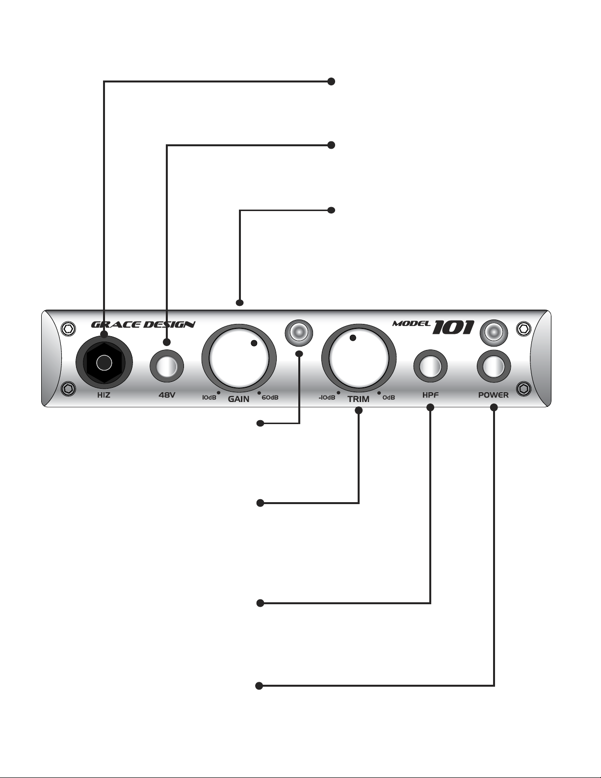
front panel controls
1/4 inch TRS instrument HI-Z input
Designed to accommodate a wide variety of high impedance
input sources, making the 101 an excellent choice as a DI box
which will flawlessly preserve the sound of the instrument.
48V PHANTOM POWER
This switch provides 48 volts to power condenser
microphones. The phantom power switch (labeled 48V)
connects the +48V power supply to pins 2 and 3 on the XLR
input connector.
GAIN CONTROL
The gain control has 11 positions and adjusts the voltage
gain on the microphone input from 10dB to 60dB in 5dB
steps. When using the instrument input, the gain range is
–10dB to 40dB in 5dB steps. NOTE: If you ordered the high
gain version of the 101 for use with ribbon microphones,
the gain range of your unit on the microphone input is 20dB
to 70dB in 5dB steps and the gain range of the instrument
input is 0dB to 50dB in 5 dB steps.
PEAK INDICATOR
The LED peak indicator, which monitors the signal
between the input and output amplifiers, illuminates
the green LED at -14dBu and illuminates the red LED at
+16dB (10dB before clipping). It is located between the
GAIN and TRIM controls.
TRIM CONTROL
The trim control provides 10dB of continuously variable
output attenuation. In the fully clockwise position the
trim is at unity (no attenuation). In the fully counter-
clockwise position the trim is at -10dB. For reference, the
3 o’clock position is -4dB and the 12 o’clock position is
-8dB. The trim control should be left in the fully clockwise
position during normal recording.
HIGH PASS FILTER
(labeled HPF) Sometimes referred to as a bass roll-off, the
high pass filter rolls off at 75Hz. This 12dB/octave filter
employs a transitional Thompson-Butterworth response
for the best combination of passband flatness and time
domain response.
POWER SWITCH
The power switch connects power from the DC input
connector to the preamplifier circuitry. When depressed,
the amber POWER LED will illuminate.
model
101
owner’s manual
page 4
 Loading...