

Page 1

GR871
14" (355 mm) Heavy Duty Chop Saw
Scie fendeuse de 355 mm (14 po) et de service intensif
Cortadora de metales de 355 mm (14")
INSTRUCTION MANUAL
GUIDE D'UTILISATION
MANUAL DE INSTRUCCIONES
INSTRUCTIVO DE OPERACIÓN, CENTROS DE SERVICIO Y PÓLIZA
DE GARANTÍA. ADVERTENCIA: LÉASE ESTE INSTRUCTIVO
ANTES DE USAR EL PRODUCTO.
GRABBER
®
Page 2

Page 3
1
English
IF YOU HAVE ANY QUESTIONS OR COMMENTS ABOUT THIS OR
ANY GRABBER TOOL, CALL US TOLL FREE AT:
1-800-477-
TURN (1-800-477-8876)
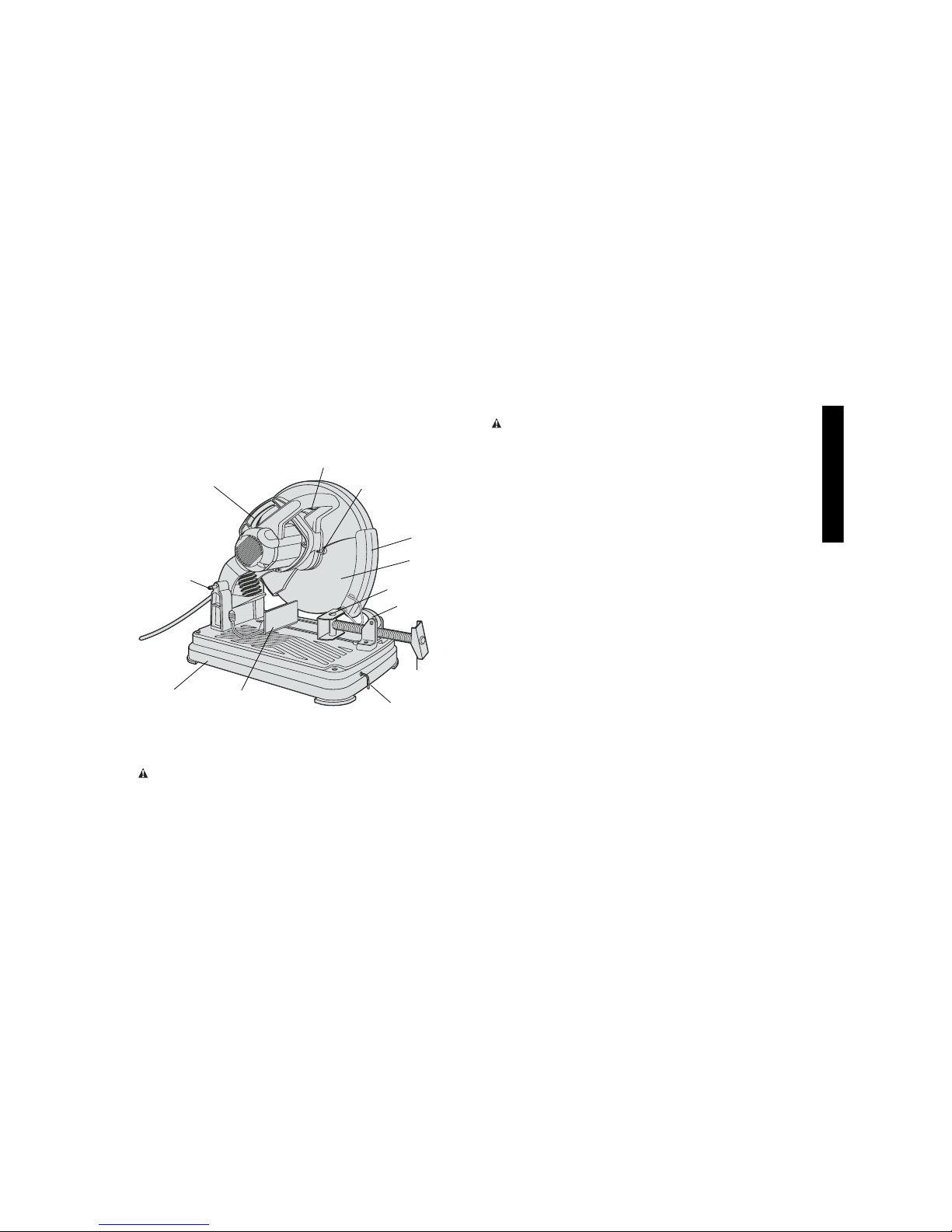
TRIGGER SWITCH
FENCE
VISE LEVER
CRANK
WHEEL
GUARD
WHEEL
VISE
CARRY
HANDLE
LOCK
DOWN PIN
WHEEL LOCK LEVER
BASE
HEX
WRENCH
WARNING: FOR YOUR OWN SAFETY READ INSTRUCTION
MANUAL BEFORE OPERATING CHOP SAW.
Important Safety Instructions
WARNING! Read and understand all instructions. Failure to
follow all instructions listed below may result in electric shock, fire
and/or serious personal injury.
SAVE THESE INSTRUCTIONS
• KEEP GUARDS IN PLACE and in working order.
• REMOVE ADJUSTING KEYS AND WRENCHES. Form habit of
checking to see that keys and adjusting wrenches are removed
from tool before turning it on.
• KEEP WORK AREA CLEAN. Cluttered areas and benches invite
injuries.
• DON’T USE IN DANGEROUS ENVIRONMENT. Don’t use power
tools in damp or wet locations, or expose them to rain. Keep work
area well lighted.
• KEEP CHILDREN AWAY. All visitors should be kept at a safe dis-
tance from work area.
• MAKE WORKSHOP KID PROOF with padlocks, master switches,
or by removing starter keys.
• DON’T FORCE TOOL. It will do the job better and safer at the rate
for which it was designed.
• USE RIGHT TOOL. Don’t force tool or attachment to do a job for
which it was not designed.
• USE PROPER EXTENSION CORD. Make sure your extension
cord is in good condition. When using and extension cord, be sure
to use one heavy enough to carry the current your product will
draw. An undersized cord will cause a drop in line voltage resulting
in loss of power and overheating. The following table shows the
correct size to use depending on cord length and nameplate
ampere rating. If in doubt, use the next heavier gage. The smaller
the gage number, the heavier the cord.
Page 4

2
English
Minimum Gage for Cord Sets
Volts Total Length of Cord in Feet
120V 0-25 26-50 51-100 101-150
240V 0-50 51-100 101-200 201-300
Ampere Rating
More Not moreAmerican Wire Gage
Than Than
0- 6 18 16 16 14
6 - 10 18 16 14 12
10 - 12 16 16 14 12
12 - 16 14 12 Not Recommended
• WEAR PROPER APPAREL. Do not wear loose clothing, neckties,
rings, bracelets, or other jewelry which may get caught in moving
parts. Nonslip footwear is recommended. Wear protective hair covering to contain long hair.
• ALWAYS USE SAFETY GLASSES. Also use face or dust mask if cut-
ting operation is dusty. Everyday eyeglasses only have impact resistant
lenses, they are NOT safety glasses.
• SECURE WORK. Use clamps or a vise to hold work when practical.
It’s safer than using your hand and it frees both hands to operate tool.
• DON’T OVERREACH. Keep proper footing and balance at all times.
• MAINTAIN TOOLS WITH CARE. Keep tools sharp and clean for best
and safest performance. Follow instructions for lubricating and changing accessories.
• DISCONNECT TOOLS before servicing; when changing accessories,
such as blades, bits, cutters, and the like.
• REDUCE THE RISK OF UNINTENTIONAL STARTING. Make sure
switch is in off position before plugging in.
• USE RECOMMENDED ACCESSORIES. Consult the instruction man-
ual for recommended accessories. The use of improper accessories
may cause risk of injury to persons.
• NEVER STAND ON TOOL. Serious injury could occur if the tool is
tipped or if the cutting tool is unintentionally contacted.
• CHECK DAMAGED PARTS. Before further use of the tool, a guard or
other part that is damaged should be carefully checked to determine that
it will operate properly and perform its intended function — check for
alignment of moving parts, binding of moving parts, breakage of parts,
mounting, and any other conditions that may affect its operation. A guard
or other part that is damaged should be properly repaired or replaced.
• DIRECTION OF FEED. Feed work into a blade or cutter against the
direction of rotation of the blade or cutter only.
• NEVER LEAVE TOOL RUNNING UNATTENDED. TURN POWER
OFF. Don’t leave tool until it comes to a complete stop.
• REPLACEMENT PARTS.
When servicing
use only identical
replacement parts.
• TO REDUCE THE RISK OF ELECTRIC SHOCK, this equipment has a
polarized plug (one blade is wider than the other.) This plug will fit in a
polarized outlet only one way. If the plug does not fit, contact a qualified
electrician to install the proper outlet. DO NOT CHANGE THE PLUG IN
ANY WAY.
Additional Safety Rules for Chop Saw
• Always wear safety goggles or other eye protection when using this tool.
• Before using, inspect each cutting wheel for cracks or flaws. If a crack
or flaw is evident—discard the wheel! The wheel should also be
inspected whenever you think the tool may have been dropped.
• When starting the tool (with a new or replacement wheel installed)
place the tool in a well protected area. If the wheel has an undetected
crack or flaw, it should burst in less than one minute. Never start the
tool with a person in line with the wheel. This includes the operator.
• In operation, avoid bouncing the wheel or giving it rough treatment.
If this occurs, stop the tool and inspect the wheel.
• Clean your chop saw periodically following the procedure in this manual.
• Do not remove wheel guard.
• Always use the vise or special fixturing to clamp work.
• Use only 14" type 1 wheels rated at 4100 rpm or higher.
• Allow cut off parts to cool before handling.
• Do not attempt to cut wood or plastic with this tool.
• NEVER CUT MAGNESIUM WITH THIS TOOL.
• Use chop saw in a well-ventilated area.
Page 5
3
English
• Turn chop saw off before removing any pieces from the base.
• DO NOT CUT ELECTRICALLY LIVE MATERIAL.
• NEVER USE A CIRCULAR SAW BLADE IN THIS CHOP SAW. DO
NOT USE TOOTHED BLADES.
• DO NOT OPERATE THIS TOOL NEAR FLAMMABLE LIQUIDS,
GASES OR DUST. Sparks from cutting or motor may ignite dust
and fumes.
SAVE THESE INSTRUCTIONS
WARNING: Some dust created by power sanding, sawing, grinding,
drilling, and other construction activities contains chemicals known to
cause cancer, birth defects or other reproductive harm. Some examples of these chemicals are:
• lead from lead-based paints,
• crystalline silica from bricks and cement and other masonry
products, and
• arsenic and chromium from chemically-treated lumber (CCA).
Your risk from these exposures varies, depending on how often you
do this type of work. To reduce your exposure to these chemicals:
work in a well ventilated area, and work with approved safety equipment, such as those dust masks that are specially designed to filter
out microscopic particles.
• Avoid prolonged contact with dust from power sanding, saw-
ing, grinding, drilling, and other construction activities. Wear
protective clothing and wash exposed areas with soap and
water. Allowing dust to get into your mouth, eyes, or lay on the skin
may promote absorption of harmful chemicals.
WARNING: Use of this tool can generate and/or disburse dust,
which may cause serious and permanent respiratory or other injury.
Always use NIOSH/OSHA approved respiratory protection appropriate for the dust exposure. Direct particles away from face and body.
Power Supply
Be sure your power supply agrees with the nameplate marking. 120
volts, “60 Hz” means alternating current (normal 120 volt, 60 Hz house
current). A voltage decrease of more than 10% will cause a loss of
power and overheating.
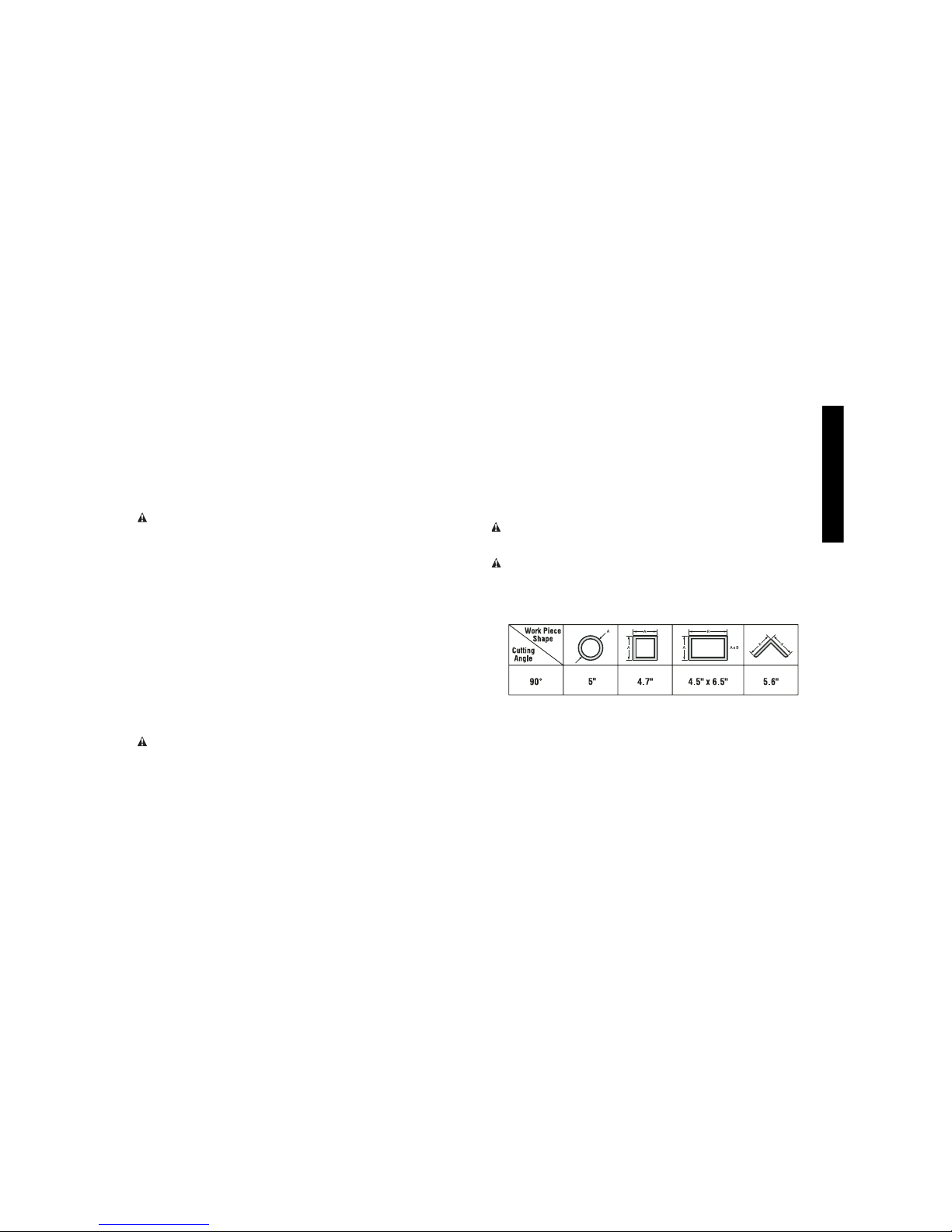
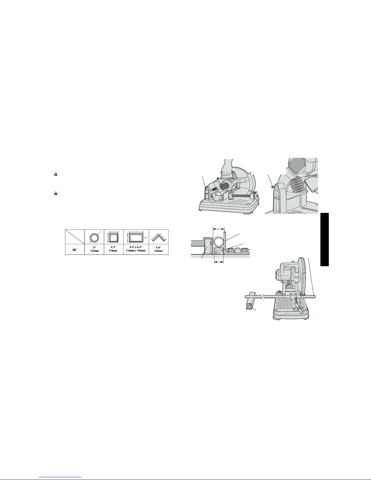
Cutting Capacity
The wide vise opening and high pivot point provide cutting capacity for
many large pieces. Use the cutting capacity chart to determine total
maximum size of cuts that can be made with a new wheel.
CAUTION: CERTAIN LARGE, CIRCULAR OR IRREGULARLY
SHAPED OBJECTS MAY REQUIRE ADDITIONAL HOLDING
MEANS IF THEY CANNOT BE HELD SECURELY IN VISE.
CAUTION: DO NOT CUT MAGNESIUM WITH THIS TOOL.
Maximum Cutting Capacity
NOTE: CAPACITY SHOWN ON CHART ASSUMES NO WHEEL WEAR
AND OPTIMUM FENCE POSITION.
Standard Equipment
1 14" (355mm) Metal Cutting Abrasive Wheel. Use only high strength
Type 1 organic bonded wheels rated 4,100 rpm or higher.
(Aluminum Oxide)
1 Wheel Wrench
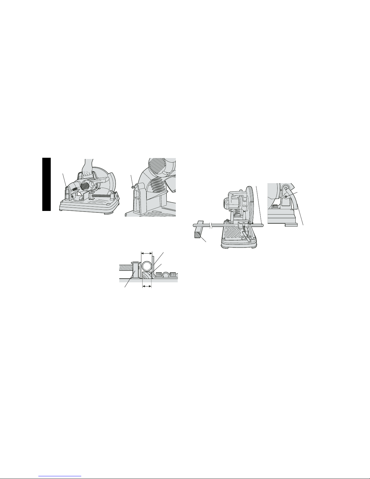
To Carry
Fold down unit to position where you can carry the saw. Push in lock
pin (Figure 1) to lock arm down.
Page 6
4
English
Unlocking
To unlock tool and raise head, depress motor arm slightly and pull lock
pin out. Motor arm will then pivot upward (see Figure 2).
Material Clamping and Supporting
• Angles are best clamped and
cut with both legs resting
against base.
• A spacer block slightly narrower than the work space
(see Figure 3) can be used to
increase wheel utilization.
• Long workpieces must be supported by a block so it will be
level with top of base (see
Figure 4). The cut off end
should be free to fall downward
to avoid wheel binding.
VISE
DIAMETER OF
WORK PIECE
FENCE
SPACER
BLOCK
WIDTH OF
SPACER BLOCK
FIG. 3
LOCK PIN
FIG. 1
LOCK
PIN
FIG. 2
Spark Deflector Adjustment
To best deflect sparks away from surrounding persons and materials, loosen the screw, adjust the spark deflector and then retighten
screw (see Figure 5).
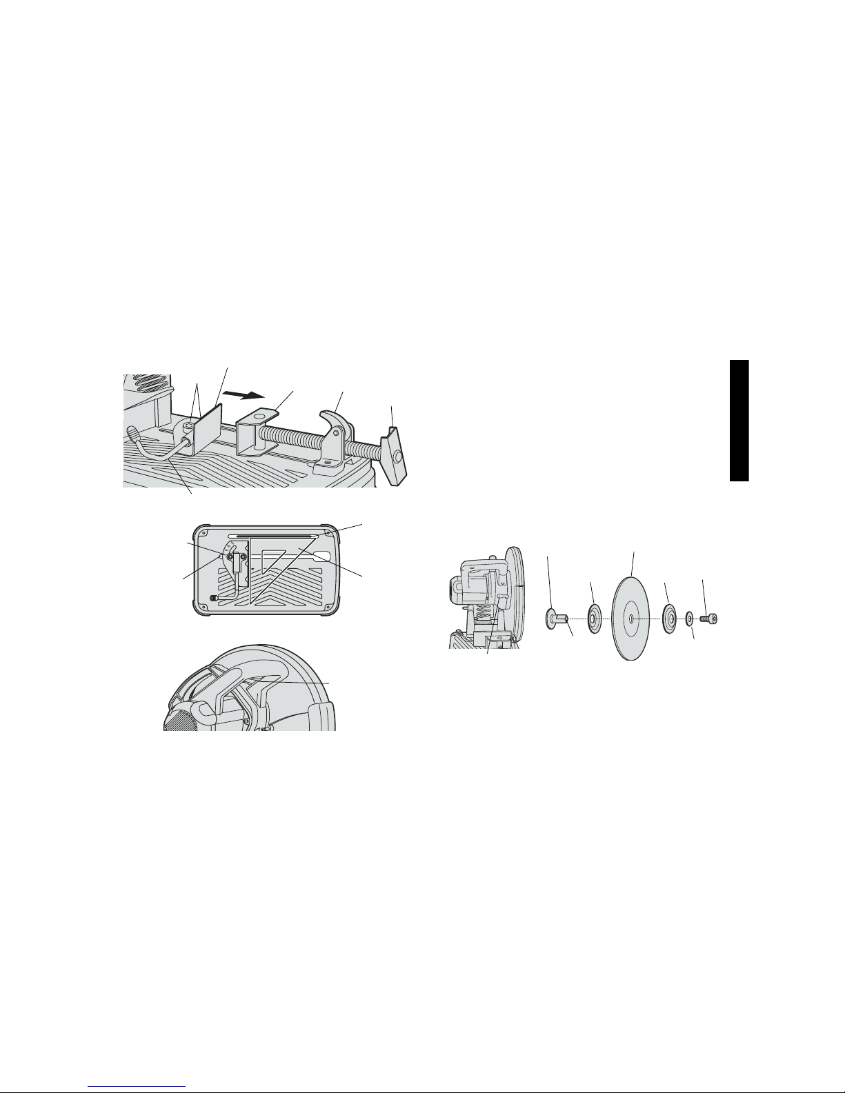
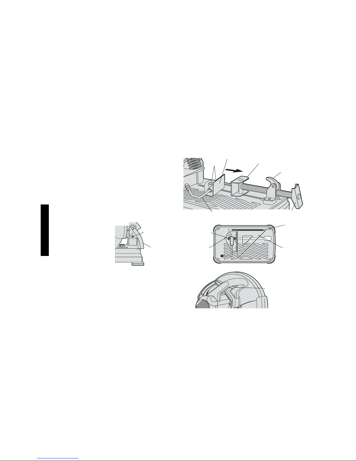
Vise Operation
Vise has a quick travel feature. To release the vise when it is clamped
tightly, turn the crank counterclockwise one or two times to remove
clamping pressure. Lift vise lever up. Pull crank assembly out as far
as desired. Vise may be shoved into work without cranking. Lower
vise lever then tighten vise on work by using crank (see Figure 6).
Fence Operation
Fence requires no wrenches to adjust. The quick release clamp lever
unlocks and locks the fence. When the lever is rotated fully forward,
the fence is unlocked. The fence can then be freely moved forward,
backward or rotated to allow for the best cutting position for a new
wheel and as the wheel wears.
Rotating the lever fully to the rear locks the fence in position selected. If
the bottom leg of the lever is not horizontal (parallel to the base), the
BLOCK
FIG. 4
CUT OFF
END
FIG. 5
SCREW
SPARK
DEFLECTOR
Page 7
5
English
fence is not locked. Lever will only lock fence when there is strong
resistance to moving it to rear. If resistance is light, adjust clamping
force by tightening slightly the two bolts holding the fence to the base.
Test by reclamping and attempt to move fence (see Figure 6).
Fence Angle Adjustment
Angle adjustment indicator is part of fence clamping system. Align
desired angle indicator line with edge of slot in base (see Figure 7). For
a more accurate square cut (Figure 7), disconnect power supply, unlock
fence, push arm down until wheel extends into base, place a square
against wheel, adjust fence against square, then lock fence into
position.
Switch
To start the tool, depress the trigger switch shown in Figure 8. To turn
the tool off, release the trigger switch. Keep hands and material from
wheel until it has coasted to a stop.
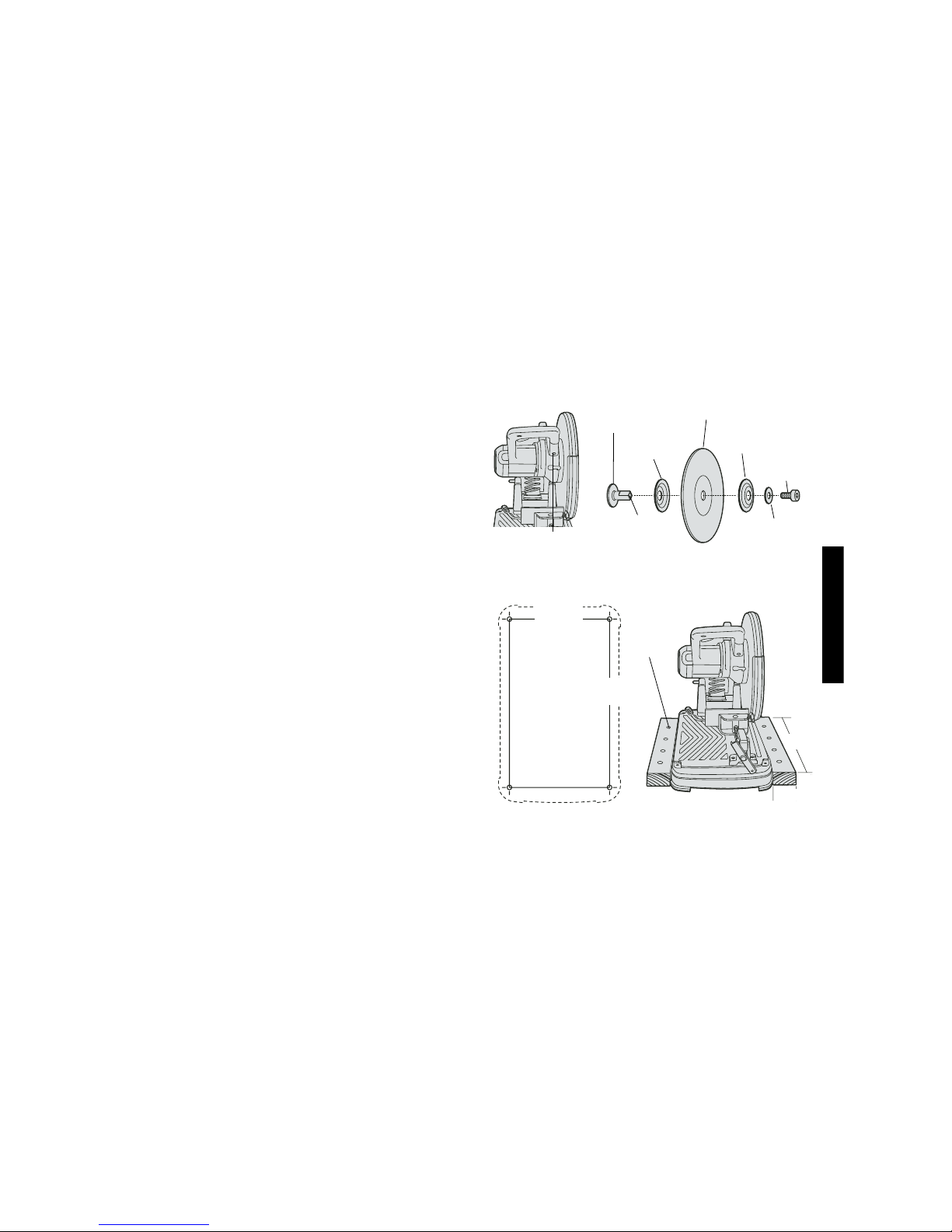
Removal and Installation of Wheels
1. Be sure tool is disconnected from power supply.
2. Push in wheel lock lever (Figure 9) and rotate wheel by hand until
wheel lock lever engages slot in inside flange to lock wheel. Loosen
SPINDLE SHAFT
FLANGE,
INSIDE
FLAT
WASHER
FLANGE,
OUTSIDE
WHEEL
FIG. 10
M10
BOLT
INTERNAL
THREAD
FIG. 9
WHEEL LOCK LEVER
TRIGGER
SWITCH
FIG. 8
WHEEL
FIG. 7
SQUARE
ANGLE
ADJUSTMENT
INDICATOR
SLOT
EDGE
VISE
LEVER
CRANK
FIG. 6
VISE
FENCE
FENCE
BOLTS
CLAMP LEVER
FORWARD
Page 8
6
English
the bolt counterclockwise in the center of the abrasive wheel with
the 8 mm hex wrench found in the holder in the base. Bolt has right
hand thread.
3. Remove the bolt, washer, outside flange, and old wheel (Fig. 10).
4. Install the new abrasive wheel by reversing the above steps.
5. Do not over tighten bolt.
DO NOT MAKE ANY ADJUSTMENT WHILE THE WHEEL IS IN MOTION.
DO NOT MAKE ANY ADJUSTMENT WHILE CHOP SAW IS PLUGGED
INTO POWER SUPPLY.
WARNING: CHECK THE WORK SURFACE THAT THE CHOP
SAW RESTS ON WHEN REPLACING WITH A NEW ABRASIVE
WHEEL. IT IS POSSIBLE THAT THE WHEEL MAY CONTACT ANY
ITEMS OR STRUCTURE THAT EXTENDS ABOVE WORK SURFACE
(UNDER THE BASE) WHEN THE ARM IS FULLY LOWERED.
NAIL
FIG. 12
17-3/8"
(441 MM)
10-1/8"
(257 MM)
FIG. 11
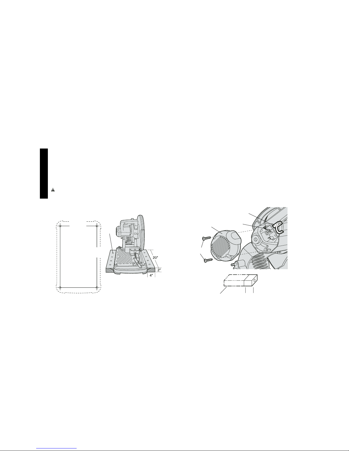
Mounting
PROCEDURE FOR PERMANENT MOUNTING
1. Drill four holes 5/16" through the work surface (Figure 11).
2. Insert 1/4-20 screws down through the holes in the base and
through holes in mounting surface. The approximant length of the
screws should be the thickness of the mounting surface plus 4".
CRADLE MOUNTING
1. Cut two boards approximately 20" long x 2" high x 4" wide (508mm
x 50mm x 100mm).
2. Place chop saw at desired work location.
3. Place boards tightly along side, and nail to work surface,
(Figure 12).
.3"
(8 MM)
FIG. 14
BRUSH
BRUSH
FIG. 13
SCREWS
END CAP
SPRING
Page 9

7
English
Motor Brush Inspection and
Replacement
Be sure tool is unplugged before inspecting brushes. Brushes should
be regularly inspected for wear. To inspect brushes, unscrew the two
end cap screws and remove end cap (see Figure 13). To remove each
brush, first unplug the shunt wire terminal connection. Then carefully
back the brush spring out of the brush box and remove brush (see
Figure 13). Brushes should slide freely in brush box. If brushes are
worn down to .3” (see Figure 14) they should be replaced. To reinstall
each brush carefully back the spring out of the brush box, insert the
brush and return the spring making sure it is pressing on the brush
and not touching the brush box. Then replace the end cap and two
screws.
Operation Tips for More Accurate Cuts
• Allow the wheel to do the cutting. Excessive force will cause the
wheel to glaze reducing cutting efficiency and/or to deflect causing inaccurate cuts.
• Adjust fence angle (Figure 7).
• Make sure material is laying flat across base.
• Properly clamp material to avoid movement and vibration.
Cleaning
Blowing dust and grit out of the main housing by means of an air hose
is recommended and may be done as often as dirt is seen collecting in
and around the air vents.
Accessories
Recommended accessories for use with your tool are available at
extra cost from your local service center. If you need any assistance
in locating any accessory, please contact GRABBER Construction
Products, 205 Mason Circle, Concord, CA 94520 or call 1-800-477TURN (1-800-477-8876).
CAUTION: The use of any other accessory not recommended
for use with this tool could be hazardous.
Repairs
To assure product SAFETY and RELIABILITY, repairs, maintenance
and adjustment should be performed by authorized service centers or
other qualified service organizations, always using identical replacement parts. ALWAYS WEAR SAFETY GLASSES. ALWAYS
SECURE WORK IN VISE. DISCONNECT TOOL FROM POWER
SUPPLY BEFORE CHANGING WHEEL.
Lubrication
Closed-type, grease-sealed ball bearings are used throughout. These
bearings have sufficient lubrication packed in them at the factory to last
the life of the chop saw.
Gears should be relubricated every 60 to 90 days, depending upon
use. This lubrication should only be attempted by experienced power
tool repair persons like the mechanics at GRABBER service centers.
The gear case should be wiped clean and 1/2 oz. (16 grams) of
GRABBER Lubricant Part No. 790206 (6 oz. tube) placed in the gear
case.
Full Warranty
GRABBER heavy duty industrial tools are warranted for one year from
date of purchase. We will repair, without charge, any defects due to
faulty materials or workmanship. For warranty repair information, call
1-800-477-TURN (1-800-477-8876). This warranty does not apply to
accessories or damage caused where repairs have been made or
attempted by others. This warranty gives you specific legal rights and
you may have other rights which vary in certain states or provinces.
Page 10

8
Français
Importantes mesures de sécurité
AVERTISSEMENT! Lire et comprendre toutes les mesures de
sécurité suivantes afin d'éviter les risques de secousses électriques,
d'incendie ou de blessures graves.
CONSERVER CES MESURES.
• MAINTENIR LES PROTECTEURS EN PLACE et en bon état.
•
RETIRER LES CLÉS DE RÉGLAGE; prendre l’habitude de s’assurer
que les clés de réglage soient retirées de l’outil avant de démarrer ce
dernier.
• BIEN DÉGAGER LA SURFACE DE TRAVAIL. Des surfaces et
des établis encombrés peuvent être la cause de blessures.
• TENIR COMPTE DU MILIEU DE TRAVAIL. Protéger les outils
électriques de la pluie. Ne pas s'en servir dans des endroits
humides ou mouillés. Bien éclairer la surface de travail.
• ÉLOIGNER LES ENFANTS. Tous les visiteurs doivent être tenus
à l'écart de l'aire de travail.
• S'ASSURER QUE L'ATELIER EST À L'ÉPREUVE DES
ENFANTS. Utiliser des cadenas, un interrupteur principal et retirer
les clés servant au démarrage.
• NE JAMAIS FORCER L'OUTIL. Afin d'obtenir un rendement sûr et
efficace, utiliser l'outil à son rendement nominal.
• UTILISER L'OUTIL APPROPRIÉ. Ne jamais exiger d'un petit outil
ou d'un accessoire le rendement d'un outil de fabrication plus
robuste.
• CORDONS DE RALLONGE. S'assurer que le cordon de rallonge
est en bon état. Lorsqu'on se sert d'un cordon de rallonge, s'assurer qu'il est de calibre approprié pour la tension nécessaire au
fonctionnement de l'outil. L'utilisation d'un cordon de calibre
inférieur occasionne une baisse de tension entraînant une perte de
puissance et la surchauffe. Le tableau suivant indique le calibre
approprié selon la longueur du cordon et les mentions de la plaque
signalétique de l'outil. En cas de doute, utiliser un cordon de calibre supérieur. Le chiffre indiquant le calibre est inversement proportionnel au calibre du cordon.
SI VOUS AVEZ DES QUESTIONS OU VOUS VOULEZ NOUS FAIRE
PART DE VOS COMMENTAIRES CONCERNANT CET OUTIL OU
TOUT AUTRE OUTIL GRABBER, COMPOSEZ SANS FRAIS LE :
1-800-477-TURN (1-800-477-8876).
INTERRUPTEUR Á DÉTENTE
GUIDE
LEVIER DE LA
BRIDE DE
SERRAGE
MANIVELLE
PROTECTEUR
LAME
BRIDE DE
SERRAGE
POIGNÉE
POUR LE
TRANSPORT
TIGE DE
VERROUILLAGE
EN POSITION
ABAISSÉE
LEVIER DE VERROUILLAGE
DE LA LAME
SOCLE
CLÉ
HEXAGONALE
AVERTISSEMENT : PAR MESURE DE SÉCURITÉ PERSONNELLE, LIRE LE GUIDE D'UTILISATION AVANT D'UTILISER LA
SCIE FENDEUSE.
Page 11

9
Français
• UTILISER DES ACCESSOIRES RECOMMANDÉS. Consulter le
guide d'utilisation pour connaître la liste des accessoires recommandés. L'utilisation de tout autre accessoire présente des risques
de blessures.
• NE JAMAIS SE TENIR DEBOUT SUR L'OUTIL. Cela présente
des risques de blessures si l'outil bascule ou si on entre en contact
avec le tranchant par inadvertance.
• VÉRIFIER LES PIÈCES ENDOMMAGÉES. Avant de continuer à
utiliser l'outil, il faut vérifier si le protecteur ou toute autre pièce
endommagée remplit bien la fonction pour laquelle il a été prévu.
Vérifier l'alignement et les attaches des pièces mobiles, le degré
d'usure des pièces et leur montage, ainsi que tout autre facteur
susceptible de nuire au bon fonctionnement de l'outil. Faire réparer ou remplacer tout protecteur ou toute autre pièce endommagée.
• SENS DE COUPE. Alimenter la pièce dans la lame seulement
dans le sens opposé à celui de rotation de la lame.
• NE JAMAIS LAISSER L'OUTIL SANS SURVEILLANCE, METTRE L'OUTIL HORS TENSION. Attendre l'immobilisation com-
plète de l'outil avant de s'en éloigner.
• POUR RÉPARER L'OUTIL, n'utiliser que des pièces de rechange
identiques.
• AFIN DE RÉDUIRE LES RISQUES DE SECOUSSES ÉLEC-
TRIQUES, l'outil est muni d'une fiche polarisée (une lame plus
large que l'autre). Ce genre de fiche n'entre que d'une façon dans
une prise polarisée. Lorsqu'on ne peut insérer la fiche à fond dans
la prise, il faut communiquer avec un électricien certifié afin de faire
installer une prise appropriée. Il ne faut pas modifier la fiche.
Mesures de sécurité relatives aux scies
fendeuses
• Toujours porter des lunettes de sécurité ou tout autre dispositif de
protection pour les yeux en utilisant l'outil.
• Avant d'utiliser l'outil, vérifier si la lame comporte des fissures ou
des défectuosités. Le cas échéant, jeter la lame. Il faut également
vérifier la lame lorsqu'on croit que l'outil est tombé.
Calibre minimal des cordons de rallonge
Tension Longueur totale du cordon en pieds
120 V 0-25 26-50 51-100 101-150
240 V 0-50 51-100 101-200 201-300
Intensité (A)
Au Au Calibre moyen de fil (AWG)
moins plus
0-6 18161614
6 - 10 18 16 14 12
10-1216161412
12 - 16 14 12 Non recommandé
• PORTER DES VÊTEMENTS APPROPRIÉS. Éviter de porter des
vêtements amples, des cravates, des bagues, des bracelets ou
d'autres bijoux qui peuvent être happés par les pièces en mouvement. Il est conseillé de porter des chaussures à semelle antidérapante. Protéger la chevelure si elle est longue.
• TOUJOURS PORTER DES LUNETTES DE SÉCURITÉ. Porter
également un masque respiratoire si le travail de coupe produit de
la poussière. Les lentilles des verres correcteurs ordinaires résistent seulement aux chocs; il ne s'agit pas de lunettes de sécurité.
• ASSUJETTIR LA PIÈCE. Immobiliser la pièce à l'aide de brides ou
d'un étau. On peut alors se servir des deux mains pour faire fonctionner l'outil, ce qui est plus sûr.
• NE PAS DÉPASSER SA PORTÉE. Toujours demeurer dans une
position stable et garder son équilibre.
• PRENDRE SOIN DES OUTILS. Conserver les outils propres et
affûtés pour qu'ils donnent un rendement supérieur et sûr. Suivre
les directives concernant la lubrification et le remplacement des
accessoires.
• DÉBRANCHER LES OUTILS lorsqu'on doit réparer l'outil ou en
changer un accessoire (comme une lame, un foret ou un couteau).
• ÉVITER LES DÉMARRAGES ACCIDENTELS. S'assurer que l'in-
terrupteur est à la position hors circuit lorsqu'on branche l'outil.
Page 12

10
Français
congénitales ou pouvant être nocifs pour le système reproductif.
Parmi ces produits chimiques, on retrouve :
• le plomb dans les peintures à base de plomb;
• la silice cristalline dans les briques et le ciment et autres produits de maçonnerie;
• l’arsenic et le chrome dans le bois de sciage ayant subi un
traitement chimique (CCA).
Le risque associé à de telles expositions peut varier selon la
fréquence avec laquelle on effectue ces travaux. Pour réduire l’exposition à de tels produits, il faut travailler dans un endroit bien ventilé et
utiliser l’équipement de sécurité approprié tel un masque anti-poussières spécialement conçu pour filtrer les particules microscopiques.
• Éviter tout contact prolongé avec la poussière soulevée par
cet outil ou autres outils électriques. Porter des vêtements de
protection et nettoyer les parties exposées du corps avec de
l’eau savonneuse. S’assurer de bien se protéger afin d’éviter
d’absorber par la bouche, les yeux ou la peau des produits chimiques nocifs.
AVERTISSEMENT : Cet outil peut produire et répandre de la pous-
sière susceptible de causer des dommages sérieux et permanents au
système respiratoire. Toujours utiliser un appareil respiratoire antipoussières approuvé par le NIOSH ou l’OSHA. Diriger les particules
dans le sens opposé du visage et du corps
.
Alimentation
Veiller à ce que la tension d'alimentation soit conforme aux exigences
de la plaque signalétique de l'outil. La mention «120 volts, 60 Hz»
signifie courant alternatif (courant domestique normal de 120 volts,
60 Hz).
Une baisse de tension de plus de 10 p. 100 entraîne une perte de
puissance et la surchauffe.
Capacité de coupe
La grande ouverture de la bride de serrage ainsi que l'articulation
exceptionnelle de la scie permettent de couper de nombreuses pièces
• Lorsqu'on met l'outil en marche (avec une lame neuve ou de
rechange), il faut le tenir dans un endroit à l'écart. Si la lame comporte une fissure ou une défectuosité non décelée, elle éclate en
moins de une minute. Ne jamais mettre l'outil en marche lorsqu'une
personne (y compris l'utilisateur) se trouve devant la scie.
• Éviter de faire faire un rebond à la lame ou de la manipuler rudement. Le cas échéant, mettre l’outil hors circuit et inspecter la lame.
• Nettoyer l’outil régulièrement conformément aux directives
d’entretien du présent guide.
• Ne jamais enlever le protecteur.
• Toujours utiliser la bride de serrage pour fixer la pièce à découper.
• Utiliser seulement des lames Type 1, 355 mm ayant une vitesse
nominale d'au moins 4 100 trs/min.
• Laisser refroidir les pièces découpées avant de les manipuler.
• Ne pas tenter de couper du bois ni de la maçonnerie avec l'outil.
• NE JAMAIS DÉCOUPER DU MAGNÉSIUM AVEC L'OUTIL.
• Utiliser la scie fendeuse seulement dans une pièce bien aérée.
• Mettre la scie fendeuse hors circuit avant de retirer les pièces qui
se trouvent dans le socle de l'outil.
• NE JAMAIS UTILISER UNE LAME DE SCIE CIRCULAIRE
AVEC LA SCIE FENDEUSE. Ne pas utiliser de lame ayant des
dents.
• NE PAS UTILISER L'OUTIL DANS DES ENDROITS OU L'AT-
MOSPHERE CONTIENT DES LIQUIDES, DES VAPEURS OU
DES POUSSIERES INFLAMMABLES. Les étincelles que pro-
duit le moteur en marche ou la coupe pourraient enflammer ces
produits.
CONSERVER CES MESURES
AVERTISSEMENT : Certains outils, tels que les sableuses élec-
triques, les scies, les meules, les perceuses ou certains autres outils
de construction, peuvent soulever de la poussière contenant des produits chimiques susceptibles d’entraîner le cancer, des malformations
Page 13
11
Français
BLOC-
SUPPORT
BRIDE DE
SERRAGE
DIAMÉTRE DE LA
PIÈCE À OUVRER
GUIDE
BLOC-
SUPPORT
LARGEUR DU
BLOC-SUPPORT
FIG. 3
FIG. 4
BOUT DÉCOUPÉ
de grandes dimensions. Consulter le tableau sur la capacité de coupe
afin de déterminer la dimension maximale totale de coupe de la nouvelle lame.
MISE EN GARDE : IL PEUT ÊTRE NÉCESSAIRE DE FIXER
CERTAINS OBJETS DE DIMENSIONS EXTRAORDINAIRES, CIRCULAIRES OU DE FORMES IRRÉGULIÈRES QUI NE PEUVENT
PAS ETRE RETENUS DANS LA BRIDE.
MISE EN GARDE : NE PAS COUPER DU MAGNÉSIUM AVEC
l'outil.
Capacité de coupe maximale
NOTE : LES CAPACITÉS INDIQUÉES SUR lE TABLEAU NE
TIENNENT PAS COMPTE DE L'USURE DE LA LAME ni de
la position optimale du guide.
CONSERVER CES MESURES.
Équipement standard
1 355 mm (14") lame abrasive à métaux – Utiliser seulement des
lames Type 1 à haute résistance à liant organique ayant une
vitesse nominale d’au moins 4 100 trs/min. (oxyde d'aluminium).
1 clé pour la lame
Transport
Plier l'outil de façon à pouvoir le transporter. Enfoncer la tige de
verrouillage (fig. 1) afin de verrouiller le bras en position abaissée.
Forme de
la pièce à
travailler
Angle
de coupe
Capacités de coupe maximales
TIGE DE
VERROUILLAGE
FIG. 1
TIGE DE
VERROUILLAGE
FIG. 2
Page 14
12
Français
Déverrouillage
Pour déverrouiller l'outil et en soulever la tête, enfoncer légèrement le
bras du moteur et retirer la tige de verrouillage. Le bras du moteur
pivote alors vers le haut (fig. 2).
Fixation et soutien du matériau
• Les angles sont mieux fixés et coupés lorsque les deux extrémités
reposent contre le socle.
• On peut se servir d'un bloc-support légèrement plus étroit que l'espace de travail (fig. 3) afin d'augmenter la capacité d'utilisation de
la lame.
• Les pièces à ouvrer longues doivent être soutenues par un bloc
afin d'être au même niveau que le dessus du socle (fig. 4). La
partie coupée devrait pouvoir tomber librement afin de ne pas
coincer la lame.
Réglage du
pare-étincelles
Afin de diriger les étincelles loin des
personnes et des choses qui se
trouvent près de l'outil, desserrer la
vis, régler le pare-étincelles et
resserrer la vis (fig. 5).
Fonctionnement de
la bride de serrage
La bride de serrage comporte une fonction de déplacement rapide.
Pour dégager la bride lorsqu'elle est bien serrée, faire tourner la
manivelle dans le sens antihoraire de un ou deux tours afin de
dégager la pression de serrage. Soulever le levier de la bride. Retirer
à l'emplacement voulu la manivelle. On peut installer la bride sans se
servir de la manivelle. Abaisser le levier de la bride puis serrer la bride
sur le matériau à l'aide de la manivelle (fig. 6).
FIG. 5
VIS
PARE-
ÉTINCELLES
LEVIER DE
LA BRIDE DE
SERRAGE
MANIVELLE
FIG. 6
BRIDE DE
SERRAGE
GUIDE
BOULONS
DU GUIDE
DÉVERROUILLER LE GUIDE
VERS L´AVANT
INTERRUPTEUR
À DÉTENTE
FIG. 8
LAME
FIG. 7
ÉQUERRE
INDICATEUR
DE RÉGLAGE
DE L´ANGLE
REBORD DE
LA FENTE
Page 15
13
Français
CLOU
FIG. 12
17-3/8PO
(441 MM)
10-1/8 PO
(257 MM)
FIG. 11
20 po
4 po
Fonctionnement du guide
On n'a pas besoin de clé pour régler le guide. Le levier de serrage à
dégagement rapide sert à verrouiller et à déverrouiller le guide.
Lorsqu'on fait tourner le levier complètement vers l'avant, le guide est
déverrouillé. On peut alors le déplacer librement vers l'avant, vers l'arrière ou le faire tourner afin d'obtenir la position de coupe optimale
pour la nouvelle lame et à mesure que la lame s'use.
Lorsqu'on fait tourner le levier complètement vers l'arrière, le guide est
verrouillé dans la position voulue. Lorsque la patte inférieure du levier
n'est pas à l'horizontale (parallèle au socle), le guide n'est pas
verrouillé. Le levier bloque le guide seulement lorsqu'il y a une forte
résistance lorsqu'on tente de le déplacer vers l'arrière. Lorsqu'il y a
peu de résistance, régler la force de serrage en serrant légèrement les
deux boulons retenant le guide au socle. Vérifier en utilisant de nouveau le levier et en tentant de déplacer le guide (fig. 6).
Réglage de l'angle du guide
L'indicateur de réglage de l'angle fait partie du système de serrage du
guide. Aligner la ligne voulue de l'indicateur sur le rebord de la fente
dans le socle (fig. 7). Pour obtenir une coupe carrée des plus précises (fig. 7), débrancher l'outil, déverrouiller le guide, abaisser le bras
jusqu'à ce que la lame soit dans le socle, placer une équerre contre la
lame et régler le guide contre l'équerre, puis verrouiller le guide en
place.
Interrupteur
Enfoncer la détente illustrée à la figure 8 pour mettre le moteur en
marche et la relâcher pour arrêter le moteur. Éloigner les mains et le
matériau de la lame jusqu'à son immobilisation complète.
RETRAIT ET INSTALLATION DE LA LAME
1. S'assurer que l'outil est débranché.
2. Enfoncer le levier de verrouillage de la lame (fig. 9) et faire tourner la lame à la main jusqu'à ce que le levier de verrouillage de la
lame s'enclenche dans la fente de la bride intérieure afin de
verrouiller la lame. Desserrer dans le sens antihoraire le boulon
ARBRE
BRIDE
INTÉRIEURE
RONDELLE
PLATE
LAME
FIG. 10
BOULON
M 10
FILET
INTERNE
FIG. 9
LEVIER DE
VERROUILLAGE
DE LA LAME
2 po
BRIDE
EXTÉRIEURE
Page 16

14
Français
AVERTISSEMENT : VÉRIFIER LA SURFACE SUR LAQUELLE
REPOSE LA SCIE FENDEUSE LORSQU'ON EN REMPLACE LA
LAME ABRASIVE. CETTE DERNIERE POURRAIT ENTRER EN
CONTACT AVEC DES ARTICLES OU DES STRUCTURES QUI
DÉPASSENT DE LA SURFACE DE TRAVAIL (SOUS LE SOCLE)
LORSQU'ON ABAISSE LE BRAS DE LA SCIE.
Montage
DIRECTIVES DE MONTAGE PERMANENT
1. Percer quatre trous d'un diamètre de 7 mm (5/16 po) dans la surface de travail (fig. 11).
2. Insérer des vis nº 20 de 1/4 po dans les trous du socle et de la surface de travail. La longueur approximative de la vis correspond à
l'épaisseur de la surface de travail plus 100 mm (4 po).
MONTAGE SUR CHEVALET
1. Découper deux planches d'une longueur de 508 mm (20 po) sur
une hauteur de 50 mm (2 po), sur une largeur de 100 mm
(4 po).
2. Placer la scie fendeuse à l'emplacement voulu.
3. Placer les deux planches tout contre chaque côté de la scie et les
clouer dans la surface de travail (fig. 12).
Inspection et remplacement des balais
du moteur
S'assurer que l'outil est débranché avant d'en vérifier les balais. Il faut
examiner ces derniers régulièrement afin d'en observer le degré
d'usure. Pour ce faire, dévisser les deux vis du bouchon et retirer ce
dernier (fig. 13). Pour retirer chaque balai, il faut d'abord débrancher
la borne montée en dérivation. Puis, il faut repousser délicatement le
ressort de balai hors de la boîte de balais et retirer le balai (fig. 13).
Les balais devraient glisser librement dans la boîte de balais. Lorsque
l'usure des balais atteint 6 mm (0,3 po) (fig. 14), il faut les remplacer.
Pour remettre les balais en place, il faut repousser délicatement le
ressort hors de la boîte de balais, insérer le balai et replacer le ressort
qui se trouve au centre de la lame abrasive à l'aide de la clé
hexagonale de 8 mm qui se trouve dans la case du socle. Le
boulon est fileté à droite.
3. Retirer le boulon, la rondelle, la bride extérieure et l'ancienne lame
(fig. 10).
4. Installer la nouvelle lame abrasive en se conformant aux étapes
précédentes dans le sens inverse.
5. Éviter de trop serrer le boulon.
N'EFFECTUER AUCUN RÉGLAGE LORSQUE LA LAME TOURNE.
N'EFFECTUER AUCUN RÉGLAGE LORSQUE LA SCIE FENDEUSE EST BRANCHÉE.
.3 PO
(8 MM)
BALAI
FIG. 14
FIG. 13
VIS
RESSORT
BALAI
BOUCHON
Page 17

15
Français
Lubrification
L'outil est entièrement monté sur des roulements à billes scellés et
graissés. Ces derniers sont lubrifiés en permanence à l'usine afin de
servir pour la durée de l'outil.
Il faut lubrifier les engrenages aux 60 à 90 jours, selon le degré
d'utilisation de l'outil. Il faut confier ces travaux aux techniciens
qualifiés des centres de service de produits GRABBER. Il faut
nettoyer le boîtier des engrenages en l'essuyant et y verser 16
grammes (1/2 oz) de lubrifiant GRABBER (pièce n° 790206 - tube de
192 g (6 oz)).
Garantie complète
Les outils industriels de service intensif GRABBER sont garantis
pendant un an à partir de la date d’achat. Toute pièce d’un outil
GRABBER qui s’avérait défectueuse en raison d’un vice de matière
ou de fabrication sera réparée sans frais. Pour obtenir de plus amples
renseignements sur les réparations couvertes para la garantie, composer e 1 (800) 477-8876. La présente garantie ne couvre pas les
accessoires ni les avaries dues aux réparations tentées ou effectuées
par des tiers. Les modalités de la présente garantie donnent des droits
légaux spécifiques. L'utilisateur peut également se prévaloir d'autres
droits selon l'état ou la province qu'il habite.
en s'assurant qu'il est appuyé contre le balai et qu'il ne touche pas à
la boîte de balais. Il faut ensuite remettre en place le bouchon et les
deux vis.
Conseils afin d'optimiser la précision de
la coupe
• Laisser la lame découper. Lorsqu'on exerce une pression excessive sur l'outil, on risque de bloquer la lame et d'en minimiser
l'efficacité ou de la dévier et de procurer une coupe imprécise.
• Régler l'angle du guide (fig. 7).
• S'assurer que le matériau repose à plat contre le socle.
• Bien fixer le matériau afin d'en empêcher le mouvement et les
vibrations.
Nettoyage
Il faut nettoyer le boîtier principal de l'outil en y soufflant de l'air
comprimé pour en chasser la poussière et les charpies dès qu'il y a
accumulation de poussière dans les évents et autour de ceux-ci.
Accessoires
Les accessoires recommandés pour chaque outil sont vendus chez
les dépositaires locaux ou les centres de service autorisés. Pour
obtenir plus d’information sur les accessoires, communiquer avec
GRABBER Construction Products, 205 Mason Circle, Concord, CA
94520 ou composer le 1-800-477-TURN (1-800-477-8876).
MISE EN GARDE : L'utilisation de tout autre accessoire non
recommandé pour l'outil peut être dangereuse.
Réparations
Pour assurer la SÉCURITÉ D’EMPLOI et la FIABILITÉ de l’outil, n’en
confier la réparation, l’entretien et les rajustements (y compris
l’inspection et le remplacement des balais) qu’au personnel d’un
centre de service GRABBER ou d’un atelier d’entretien autorisé
n’utilisant que des pièces de rechange identiques.
Page 18

16
Español
¡ADVERTENCIA! Lea y asegúrese de entender todas las
instrucciones. El no hacerlo puede originar riesgos de choque eléc-
trico, incendio y/o lesiones personales de gravedad.
CONSERVE ESTAS INSTRUCCIONES
Instrucciones importantes de seguridad
• CONSERVE LAS GUARDAS EN SU SITIO y listas para trabajar.
• RETIRE LAS LLAVES DE AJUSTE O PRESIÓN. Desarrolle el
hábito de verificar que las llaves, incluyendo las llaves de
ajuste, hayan sido retiradas del eje antes de poner en marcha la
herramienta.
• CONSERVE LIMPIA EL AREA DE TRABAJO. Las áreas y bancos
con objetos acumulados en desorden propician los accidentes.
• NO SE EMPLEE EN AMBIENTES PELIGROSOS. No utilice
herramientas eléctricas en ligares inundados o mojados, ni las
exponga a la lluvia. Conserve bien iluminada el área de trabajo.
• CONSERVE APARTADOS A LOS NIÑOS. Todos los visitantes
deben permanencer a distancia segura de la zona de trabajo.
• HAGA SU TALLER A PRUEBA DE NIÑOS con candados, inter-
ruptores maestros y retirando las llaves de encendido.
• NO FUERCE LA HERRAMIENTA. Esta cumplirá mejor con su tra-
bajo y de manera más segura bajo las especificaciones para las
que se diseñó.
• EMPLEE LA HERRAMIENTA ADECUADA. No fuerce una her-
ramienta o sus dispositivos en una tarea para los que no han sido
diseñados.
• UTILICE UN CABLE DE EXTENSION ADECUADO. Asegúrese
que su extensión esté en buenas condiciones. Cuando utilice una
extensión, asegúrese de emplear una que soporte la corriente que
su herramienta necesita. Una extensión con calibre insuficiente
provocará una caída en el voltaje de la línea, ocasionando pérdida
de potencia y sobrecalentamiento. El cuadro siguiente muestra el
calibre correcto a utilizarse de acuerdo con la longitud y el amper-
GATILLO INTERRUPTOR
GUIA
PALANCA DE
LA PRENSA
MANIVELA
GUARDA
DEL DISCO
PRENSA
ASA DE
ACARREO
PERNO DE
SEGURIDAD
PALANCA DEL
SEGURO
DEL DISCO
BASE
LLAVE
ALLEN
DISCO
Epecificaciones
Tensión de alimentación: 120 V
Potencia nominal: 1650 W
Frecuencia de operación: 50/60 Hz
Consumo de corriente: 15 A
¡ADVERTENCIA! PARA SU PROPIA SEGURIDAD
LEA ESTE MANUAL DE INSTRUCCIONES ANTES DE
UTILIZAR LA CORTADORA DE METALES.
Page 19

17
Español
aje indicado en la placa de identificación. Si tiene dudas, utilice el
calibrte siguiente. Mientras más pequeño sea el número del calibre, mayor será su capacidad.
Calibre mínimo para cordones de extensión
Volts Longitud total del cordón en metros
120V 0-7,6 7,6-15,2 15,2-30,4 30,4-45,7
240V 0-15,2 15,2-30,4 30,4-60,9 60,9-91,4
AMPERAJE
Más No más Calibre del cordón AWG
de de
0- 6 18 16 16 14
6 - 10 18 16 14 12
10 - 12 16 16 14 12
12 - 16 14 12 No recomendado
• VISTA LAS PRENDAS ADECUADAS. No utilice prendas de vestir
flojas, guantes, corbatas, anillos, brazaletes ni otras piezas de
joyería que pudiesen quedar atrapadas en las partes móviles. Se
recomienda el empleo de calzado antiderrapante. Cúbrase el
cabello si lo tiene largo.
• SIEMPRE UTILICE GAFAS DE SEGURIDAD. También utilice una
máscara contra polvo si la operación a efectuar lo produce. Los
anteojos de uso diario solamente tienen lentes resistentes al
impacto, NO SON anteojos de seguridad.
• SUJETE BIEN LA PIEZA DE TRABAJO. Sujete la pieza de
trabajo con abrazaderas o en las mordazas de un torno de banco
cuando sea práctico hacerlo. Es más seguro que sujetarla con la
mano y le permite usar ambas manos para manejar la
herramienta.
• NO SE SOBREEXTIENDA. Conserve siempre bien apoyados los
pies, lo mismo que el equilibrio.
• CUIDE SUS HERRAMIENTAS. Conserve sus herramientas
afiladas y limpias para que funcionen mejor y de manera más
segura. Siga las instrucciones de cambio de accesorios.
• DESCONECTE LA HERRAMIENTAS antes de efectuarles
servicio y cuando les cambie acesorios, como cuchillas, brocas y
similares.
• REDUZCA EL RIESGO DE ENCENDIDO ACCIDENTAL.
Asegúrese que el interruptor esté en posición de apagado antes de
conectar la herramienta.
• UTILICE LOS ACCESORIOS RECOMENDADOS. Busque en el
manual de instrucciones los accesorios recomendados. El uso de
accesorios inadecuados puede causar riesgos de lesiones.
• NUNCA SE PARE EN LA HERRAMIENTA. Puede provocarse
lesiones graves si la herramienta se vuelca o si hace contacto
accidental con la herramienta de corte.
• REVISE LAS PARTES DAÑADAS. Antes de seguir utilizando la
herramienta, debe revisar cuidadosamente una guarda o cualquier
otra pieza que esté dañada para determinar si cumplirá
adecuadamente con su función; revise la alineación de las piezas
móviles, sus montajes, ruptura de partes y cualesquiera otras
condiciones que pudiesen afectar su operación. Repare o
reemplace las piezas dañadas.
•
DIRECCIÓN DE ALIMENTACIÓN. Introduzca la pieza que desea
cortar únicamente contra la dirección de rotación el disco de corte o
de la sierra.
• NUNCA DEJE LA HERRAMIENTA EN FUNCIONAMIENTO Y
DESATENDIDA. APAGUELA. No deje la herramienta hasta que
se haya detenido por completo.
•
REPUESTOS. Utilice solamente piezas de repuesto idénticas..
•
PARA REDUCIR EL RIESGO DE CHOQUES ELÉCTRICOS,
este
equipo tiene un enchufe polarizado (donde una clavija es más
ancha que la otra). Este enchufe entra en un tomacorrientes polarizado solamente en una posición. Si el enchufe no entra en el
receptáculo, contacte un electricista calificado para que le instale el
tomacorrientes adecuado. NO CAMBIE EL ENCHUFE DE NINGUNA
MANERA.
CONSERVE ESTAS INSTRUCCIONES
ADVERTENCIA : Parte del polvo creado al lijar, aserruchar, moler
o perforar con máquina, así como al realizar otras actividades de la
construcción, contiene substancias químicas que se sabe producen
Page 20

18
Español
cáncer, defectos congénitos u otras afecciones reproductivas.
Algunos ejemplos de esas substancias químicas son:
• plomo de pinturas a base de plomo,
• sílice cristalizado de ladrillos y cemento y otros productos de
albañilería, y
• arsénico y cromo de la madera químicamente tratada (CCA).
El riesgo al contacto con estas substancias varía, según la frecuencia
en que se haga este tipo de trabajo. Para reducir la exposición a esas
substancias químicas: trabaje en un área bien ventilada, y trabaje con
equipos de seguridad aprobados, tales como máscaras contra el polvo
especialmente diseñadas para filtrar las partículas microscópicas.
• Evite el contacto prolongado con polvos originados por lijar,
aserrar, esmerilar, taladrar y otras actividades constructivas.
Vista ropas protectoras y lave las áreas expuestas con agua y
jabón. Permitir que el polvo se introduzca en su boca, ojos, o
dejarlo sobre la piel promueve la absorción de químicos dañinos.
ADVERTENCIA: Toda persona que entre al área de trabajo
deberá usar una máscara antipolvo o protección respiratoria. El filtro
debería ser reemplazado a diario o cuando el usuario tenga dificultad
para respirar. Puede encontrar la máscara antipolvo apropiada
aprobada por NIOSH/OSHA en su ferretería local.
Instrucciones de seguridad para
cortadoras de metales
• Siempre utilice anteojos de seguridad cuando emplee esta
herramienta.
• Antes de usar la unidad, revise los discos de corte en busca de
cuarteaduras. Si hay cuarteaduras, deseche el disco. También
debe revisarse el disco si usted piensa que se ha golpeado.
• Cuando encienda la herramienta (con un disco nuevo, o después
de haberlo cambiado), colóquela en un área protegida. Si el disco
se cuartea, puede estallar en menos de un minuto. Nunca encienda la unidad si hay personas en línea con la herramienta, incluyendo al operador.
• Durante la operación, evite que el disco rebote. Si esto ocurre,
detenga la unidad y revise el disco.
• Limpie su sierra para metales periódicamente siguiendo los procedimientos mencionados en la sección relativa al mantenimiento.
• No quite la guarda del disco.
• Utilice la prensa para asegurar la pieza de trabajo.
• Unicamente utilice discos de 355 mm, Tipo 1 fabricados para 4100
o más rpm.
• Permita que las piezas cortadas se enfríen antes de manipularlas.
• No intente cortar madera o mampostería con esta herramienta.
• NUNCA CORTE MAGNESIO CON ESTA HERRAMIENTA.
• Utilice la cortadora de metales en un área bien ventilada.
• Apague la sierra antes de quitar cualquier pieza de la base.
• NO CORTE MATERIAL ELECTRICAMENTE VIVO.
• NUNCA UTILICE DISCOS PARA SIERRA CIRCULAR EN ESTA
SIERRA. NO EMPLEE DISCOS DENTADOS.
• NO EMPLEE ESTA HERRAMIENTA CERCA DE LIQUIDOS,
GASES, O POLVOS INFLAMABLES. Las chispas originadas en
el corte o en el motor pueden originar la ignición de estos polvos y
vapores.
Alimentación
Asegúrese que su toma de corriente concuerda con la marca de la
placa de identificación. 120 volts, 60 Hz significa corriente alterna
(corriente doméstica normal a 120 volts y 60 Hz).
Una disminución de más del 10% en la intensidad causará pérdida de
potencia y sobrecalentamiento.
Capacidad de corte
La gran capacidad de abertura de la prensa y el alto punto de pivoteo
proporcionan capacidad para cortar piezas muy grandes. Use la tabla
que sigue para determinar el tamaño máximo de los cortes que podrá
hacer con un disco nuevo.
Page 21

19
Español
PRECAUCION: ALGUNOS OBJETOS GRANDES, O DE
FORMA IRREGULAR PUEDEN REQUERIR ALGUN MEDIO DE
SUJECION ADICIONAL AL NO PODERSE SUJETAR CON LA
PRENSA.
PRECAUCION: NO CORTE MAGNESIO CON ESTA
HERRAMIENTA.
Capacidad máxima de corte
NOTA: LA CAPACIDAD MOSTRADA EN LA TABLA ASUME QUE
NO HAY DESGASTE EN EL DISCO.
Equipo estándar
1 Disco abrasivo dec 355 mm para corte de metales. Utilice única-
mente discos con ligaduras orgánicas de alta resistencia fabricados para 4100 o más rpm. (Oxido de aluminio)
1 Llave para el disco
Para transportar la unidad
Pliegue la unidad de manera que pueda transportarla. Empuje el
perno de seguridad (figura 1) para asegurar el brazo en la posición
baja.
Para desasegurar
Para desasegurar y elevar la cabeza, oprima el brazo del motor ligeramente y tire del perno de seguridad hacia afuera. El brazo del
motor subirá (observe la figura 2).
PERNO DE
SEGURIDAD
FIG. 1
PERNO DE
SEGURIDAD
FIG. 2
BLOQUE
PRENSA
DIAMETRO DE LA
PIEZA DE DE TRABJO
BLOQUE
ESPACIADOR
ANCHO DEL BLOQUE
ESPACIADOR
FIG. 3
FIG. 4
EEMO QUE SE
DESPRENDE
GUIA
Page 22

20
Español
PALANCA DE
LA PRENSA
MANVELA
PRENSA
GUIA
TORNILLOS
DE LA GUIA
PALANCA DE PRENSADO
ADELANTE
DISCO
FIG. 7
ESCUADRA
INDICADOR DE
AJUSTE DE
ANGULOS
BORDE DE
RANURA
Sujeción y soporte de material
• Los ángulos se sujetan y cortan mejor con ambas patas apoyadas
contra la base.
• Puede emplearse un bloque espaciador ligeramente más angosto que el espacio de trabajo (figura 3) para aumentar la utilización
del disco.
• Las piezas grandes deben apoyarse por un bloque de manera
que queden a nivel con la superficie de la base (figura 4). El
extremo que se desprende debe quedar libre para caer para evitar que el disco se atore.
Ajuste del deflector de chispas
Para alejar las chispas de las personas y materiales a su alrededor de
la mejor manera posible, afloje el tornillo, ajuste el deflector y apriete
el tornillo (observe la figura 5).
Operación de la prensa
La prensa cuenta con un sistema de movimiento rápido. Para liberar
la prensa cuando esté apretada, gire la manivela en sentido contrario
a las manecillas del reloj una o dos veces para relajar la presión. Suba
la palanca de la prensa. Tire del montaje de la manivela hacia fuera
cuanto desee. La prensa puede utilizarse sin usar la manivela. Sin
embargo, termine de apretarla siempre utilizando la manivela
(observe la figura 6).
Ajuste del ángulo de la guía
El indicador del ángulo de ajuste es parte del sistema de prensado a
la guía. Haga coincidir la línea deseada en el indicador de ángulos
con el borde de la ranura en la base (figura 7). Para un corte a
escuadra más preciso (figura 7), desconecte la alimentación de corriente, desasegure la guía, empuje el brazo hacia abajo hasta que el
disco traspase la base, coloque una escuadra contra el disco, ajuste
la guía contra la escuadra y asegure la guía en su posición.
FIG. 5
SCREW
DEFLECTOR
DE CHIDPAS
FIG. 6
Page 23

21
Español
Interruptor
Para encender la herramienta, oprima el gatillo interruptor ilustrado en
la figura 8. Para apagarla, libere el gatillo. Conserve las manos y el
material alejados del disco hasta que este se haya detenido completamente.
Remoción e instalación de discos
1. Asegúrese que la herramienta está desconectada de la toma de
corriente.
2. Asegure el disco con la palanca del seguro del disco (fig. 9) y gire
el disco a mano hasta que la palanca del seguro se trabe en la
ranura correspondiente para asegurar el disco. Afloje el tornillo
que se encuentra al centro de la rueda abrasiva en sentido contrario a las manecillas del reloj con la llave hexagonal de 8 mm
que se está en el porta llaves de la base. El tornillo es de cuerda
derecha.
3. Quite el tornillo, la roldana, la arandela exterior y el disco abrasivo
usado (fig. 10).
4. Instale el nuevo disco abrasivo invirtiendo los pasos anteriores.
5. No apriete demasiado el tornillo.
NO REALICE NINGÚN AUSTE MIENTRAS QUE EL DISCO SE
ENCUENTRE EN MOVIMIENTO.
NO REALICE NINGÚN AUSTE MIENTRAS QUE LA CORTADORA
DE METALES SE ENCUENTRE CONECTADA A UNA TOMA DE
CORRIENTE.
INTERRUPTOR
DE GATILLO
FIG. 8
FLECHA
ARANDELA
INTERIOR
ROLDANA
PLANA
ARANDELA
EXTERIOR
DISCO
FIG. 10
M10
TORNILLO
ROSCA
INTERIOR
FIG. 9
PALANCA DE
SEGURO DEL DISCO
CLAVO
FIG. 12
17-3/8"
(441 MM)
10-1/8"
(257 MM)
FIG. 11
Page 24

22
Español
ADVERTENCIA: VERIFIQUE LA SUPERFICIE DE TRABAJO
SOBRE LA QUE DESCANSA LA CORTADORA CUANDO REEMPLACE UN DISCO ABRASIVO, ES POSIBLE QUE EL DISCO
HAGA CONTACTO CON LA SUPERFICIE DE TRABAJO (A
TRAVES DE LA BASE) CUANDO EL BRAZO SE HA BAJADO
COMPLETAMENTE.
Montaje
Procedimiento para montaje permanente
1. Perfore cuatro barrenos de 7,9 mm (5/16") en la superficie de
trabajo (fig. 11).
2. Inserte tornillos de 6 mm (1/4-20) a través de la parte inferior de
la superficie de trabajo, hasta las patas, en la base de la
herramienta. La longitud del tornillo debe ser igual al espesor de
la superficie de trabajo más 100 mm (4").
MONTAJE DE CUNA
1. Corte dos tablas de 50 cm (20") de longitud por 5 cm (2") de alto
por 10 cm (4") de ancho.
2. Coloque la sierra en el lugar deseado.
3. Coloque los tableros apretados contra los lados, y clávelos a la
superficie de trabajo (fig. 12).
Carbones del motor
Asegúrese que la herramienta esté desconectada antes de revisar los
carbones. Los carbones deben revisarse frecuentemente en busca de
desgaste. Para revisarlos, afloje los tornillo y quite la tapa del extremo
(observe la figura 13). Para quitar cada carbón, desconecte primero
la conexión terminal del cable de derivación. A continuación, saque
cuidadosamente el resorte y el carbón de la caja del carbón (observe
la figura 13). Los carbones deben deslizarse libremente en la caja. Si
los carbones se desgastan hasta una longitud de 0,76 cm (0,3”) (figura 14) deberán reemplazarse. Para reinstalar los carbones, saque
cuidadosamente el resorte de la caja, inserte el carbón y coloque de
.3"
(8 MM)
CARBONE
FIG. 13
FIG. 14
TORNILLOS
TAPA
CARBONE
RESORTE
nuevo el resorte, asegurándose que éste esté oprimiendo al carbón y
no haga contacto con la caja. A continuación, coloque de nuevo la
tapa del extremo y los dos tornillos.
Recomendaciones para obtener cortes
más precisos
• Permita que el disco haga el corte. Excesiva fuerza ocasionará
que el disco se cristalice, reduciendo la eficiencia del corte y (o)
se desvíe haciendo cortes no rectos.
Page 25

23
Español
MEXICO, D.F.
Eje Central Lázaro Cárdenas No. 18
Local D, Col. Obrera (55) 5588 9377
MERIDA, YUC
Calle 63 #459-A - Col. Centro (999) 928 5038
MONTERREY, N.L.
Av. Francisco I. Madero No.831 - Col. Centro (81) 8375 2313
PUEBLA, PUE
17 Norte #205 - Col. Centro (222) 246 3714
QUERETARO, QRO
Av. Madero 139 Pte. - Col. Centro (442) 214 1660
SAN LUIS POTOSI, SLP
Av. Universidad 1525 - Col. San Luis (444) 814 2383
TORREON, COAH
Blvd. Independencia, 96 Pte. - Col. Centro (871) 716 5265
VERACRUZ, VER
Prolongación Díaz Mirón #4280 - Col. Remes (229) 921 7016
VILLAHERMOSA, TAB
Constitución 516-A - Col. Centro (993) 312 5111
PARA OTRAS LOCALIDADES LLAME AL: (55) 5326 7100
Póliza de Garantía
IDENTIFICACIÓN DEL PRODUCTO:
Sello o firma del Distribuidor.
Nombre del producto: _____________ Mod./Cat.: _____________
Marca: _____________________ Núm. de serie:_____________
(Datos para ser llenados por el distribuidor)
Fecha de compra y/o entrega del producto: __________________
Nombre y domicilio del distribuidor donde se adquirió el producto:
_____________________________________________________
Este producto está garantizado por un año a partir de la fecha de
entrega, contra cualquier defecto en su funcionamiento, así como en
materiales y mano de obra empleados para su fabricación. Nuestra
• Ajuste el ángulo de la guía (figura 7).
• Asegúrese que el material quede plano sobre la base.
• Sujete el material apropiadamente para evitar movimientos y
vibraciones.
Limpieza
Debe sopletearse la carcaza con una manguera con aire comprimido,
tan a menudo como vea que se acumula mugre alrededor de las
tomas de aire.
Lubricación
Se han empleado baleros de bolas sellados de tipo cerrado. Estos
baleros cuentan con la lubricación suficiente para soportar durante
toda la vida de la cortadora de metales.
Los engranes deben relubricarse cada 60 a 90 días, dependiendo del
uso. Esta lubricación deberá ser efectuada por personal capacitado,
como los mecánicos de los centros de servicio autorizados
GRABBER. La caja de engranes debe limpiarse y deben añadirse
16 gramos (1/2 oz.) de lubricante GRABBER (parte No. 790206).
Reparaciones
Para garantizar la SEGURIDAD y la CONFIABILIDAD, deberán hacerse reparaciones, mantenimiento y ajustes de esta herramienta en
los centros autorizados de servicio GRABBER u otras organizaciones
autorizadas. Estas organizaciones prestan servicio a las herramientas
GRABBER y emplean siempre refacciones legitimas GRABBER.
PARA REPARACION Y SERVICIO DE SUS HERRAMIENTAS
ELÉCTRICAS, FAVOR DE DIRIGIRSE AL CENTRO
DE SERVICIO MAS CERCANO
CULIACAN, SIN
Av. Nicolás Bravo #1063 Sur - Col. Industrial Bravo (667) 7 12 42 11
GUADALAJARA, JAL
Av. La Paz #1779 - Col. Americana Sector Juárez (33) 3825 6978
Page 26

24
Español
garantía incluye la reparación o reposición del producto y/o componentes sin cargo alguno para el cliente, incluyendo mano de obra, así
como los gastos de transportación razonablemente erogados derivados del cumplimiento de este certificado.
Para hacer efectiva esta garantía deberá presentar su herramienta
y esta póliza sellada por el establecimiento comercial donde se
adquirió el producto, de no contar con ésta, bastará la factura de compra.
EXCEPCIONES.
Esta garantía no será válida en los siguientes casos:
• Cuando el producto se hubiese utilizado en condiciones distintas
a las normales;
• Cuando el producto no hubiese sido operado de acuerdo con el
instructivo de uso que se acompaña;
• Cuando el producto hubiese sido alterado o reparado por personas distintas a las enlistadas al final de este certificado.
Anexo encontrará una relación de sucursales de servicio de fábrica,
centros de servicio autorizados y franquiciados en la República
Mexicana, donde podrá hacer efectiva su garantía y adquirir partes,
refacciones y accesorios originales.
Garantía Completa
Las herramientas industriales GRABBER están garantizadas durante
un año a partir de la fecha de compra. Repararemos, sin cargos,
cualquier falla debida a material o mano de obra defectuosos. Por favor
regrese la unidad completa, con el transporte pagado, a cualquier
Centro de Servicio para Herramientas Industriales de D
EWALT o a las
estaciones de servicio autorizado enlistadas bajo “Herramientas
Eléctricas” en la Sección Amarilla. Esta garantía no se aplica a los
accesorios ni a daños causados por reparaciones efectuadas por
terceras personas. Esta garantía le otorga derechos legales
específicos, y usted puede tener otros derechos que pueden variar de
estado a estado.
IMPORTADOR: BLACK & DECKER S.A. DE C.V.
BOSQUES DE CIDROS ACCESO RADIATAS NO. 42
BOSQUES DE LAS LOMAS C.P., 05120 MEXICO, D.F.
TEL 3-26-71-00
Page 27

Page 28

GRABBER Construction Products, 205 Mason Circle, Concord, CA 94520
Copyright © 2005
Form# 634668-00
 Loading...