

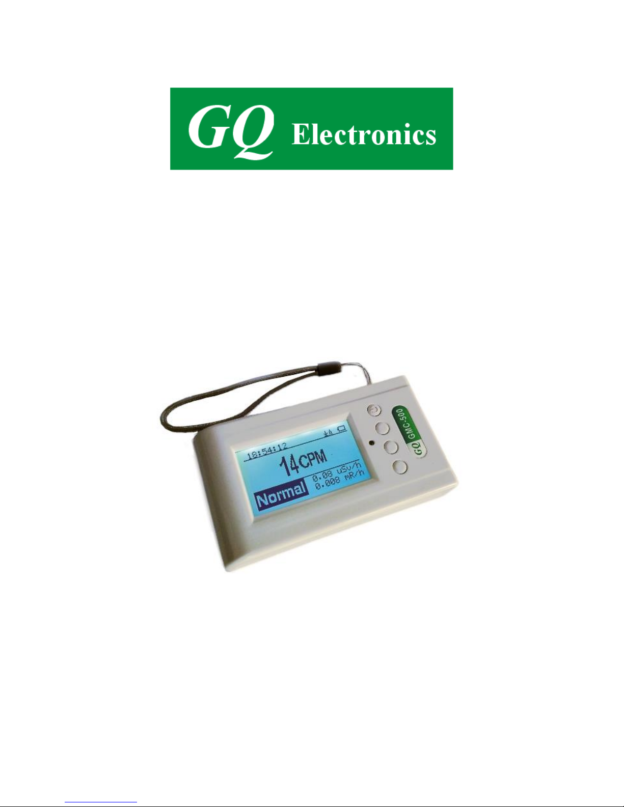
GQ GMC-500/GMC-500+
Geiger Counter
User Guide
GQ Electronics LLC
Revision 1.2
Sep-2017

2
Document Revision History:
Re.1.20 ,Sep-2017
Re.1.01 ,Apr-2017
Re.1.00 ,Feb-2017

3
Table of Contents
User Guide ........................................................................................................................... 1
Table of Contents .................................................................................................................. 3
Overview ................................................................................................................................... 5
Specifications: .................................................................................................................. 5
Packing List: ..................................................................................................................... 6
How it works? ............................................................................................................................ 6
Caution ....................................................................................................................................... 6
Background Safe Levels ............................................................................................................ 6
Hardware setup ............................................................................................................... 7
Software set up ................................................................................................................ 7
Verify USB driver installation in Windows ........................................................................... 8
S1 key ............................................................................................................................... 9
S2 key ............................................................................................................................... 9
S3 key ............................................................................................................................... 9
S4 key .............................................................................................................................. 9
Power saving mode ........................................................................................................ 9
Popup Windows ............................................................................................................. 10
Graphic User Interface (GUI) .............................................................................................. 10
Graphic Icons: ................................................................................................................ 10
Dual Display Modes ................................................................................................................ 12
Display Modes ......................................................................................................................... 13
Graphic Mode: ............................................................................................................... 13
Text Mode:...................................................................................................................... 13
Large Font Mode: .......................................................................................................... 14
User Option .................................................................................................................... 15
Alarm Set ........................................................................................................................ 15
Date and Time setting .................................................................................................. 16
Data Saving Setting ...................................................................................................... 16
Threshold Data Saving Setting ................................................................................... 17
Add Note or Add Location for data saving ................................................................ 17
Note/Location Input ....................................................................................................... 18
Erase Saved History Data ........................................................................................... 18
Display Option................................................................................................................ 18
Swivel Display Option .................................................................................................... 18
WiFi Setup and Check .................................................................................................. 19
WiFi IP address ............................................................................................................. 19
WiFi Mac address.......................................................................................................... 19
WiFi Signal Level Checking ......................................................................................... 19
Internet Data Server Setting ........................................................................................ 20
Website server ............................................................................................................... 20
URL for Website server ................................................................................................ 20
Website server User ID ................................................................................................ 20
Website server Geiger Counter ID ............................................................................. 21
WiFi Data Logging Period ............................................................................................ 21
WiFi Data Logging Testing .......................................................................................... 21
Calibrate the reading .................................................................................................... 22
Factory reset .................................................................................................................. 23
Battery Status ................................................................................................................ 23
Battery Type ................................................................................................................... 23
Power saving mode ...................................................................................................... 24
Motion Detection............................................................................................................ 24
Reset Total Count ......................................................................................................... 24
Gyroscope Data Display .............................................................................................. 25
Communication Baud Rate .......................................................................................... 25

4
Reverse Display ............................................................................................................ 25
Contrast Adjustment ..................................................................................................... 25
Timed Count ................................................................................................................... 26
Set a schedule ............................................................................................................... 26
Set Timed Count Duration ........................................................................................... 26
Start a Timed Count ...................................................................................................... 27
About ............................................................................................................................... 28
Model information .......................................................................................................... 28
Firmware version ........................................................................................................... 28
Unit serial number ......................................................................................................... 28
GQ GMC Data Viewer Software ......................................................................................... 29
Online Geiger Counter World Map ..................................................................................... 32
www.GMCmap.com ................................................................................................................ 32
Software ................................................................................................................................... 32
Auto Submit Data Protocol ...................................................................................................... 32
Applications .................................................................................................................... 33
Stationary Application ................................................................................................... 33
Other technical details you may want to know ................................................................. 34
Data Port ......................................................................................................................... 34
USB Port ......................................................................................................................... 34
Data collection time...................................................................................................... 34
Extend battery operating time ..................................................................................... 34
Third party software developers ................................................................................. 34

5
Overview
The.GQ GMC-500 digital Geiger Muller Counter is designed to be a portable and convenient device.
It can be used as industrial, commercial maintenance, research, evaluation, simulation and other
analytical or scientific applications in areas such as industrial plants, public utilities, universities,
laboratories, and electronic repair shops. The device comes with built in audible and visual signals
for the level of radiation detected. It can be used for radiation detection and monitoring both indoor
and outdoor, as well as in other similar environments. It features automatic data recording. It can
continually monitor the radiation and log the data each second into internal memory. When
connected to a PC, software can download the radiation history data to the computer and the user is
able to analyze those data later. The GQ GMC-500 installed a high contrast black/white LCD
module, one front LED indicator and one analog data port. The analog data port can be connected
to any third party device application as data input.
The GMC-500 installed a WiFi module, user is able to log the data via WiFi wirelessly.
The device is equipped with an USB port, utilized for communication and external power
supply/charging of the internal rechargeable Li-Ion 3.6V/3.7V battery.
The GQ GMC-500 internal rechargeable battery can be charged with the a standard USB port, USB
charger or with a computer USB port. Using the external power, continuous data monitoring is
possible. Using either power adapter you will not have to worry about the batteries charge condition
or any data loss.
The main board also has a real time clock on board for time related data logging purposes.
The GMC-500 installed multiple sensors to ensure full scale/range measurement and higher
accuracy. .
Specifications:
Range of dose rate indications, µSv/h 0.00 to ~4250
(0.00 to ~42500 on GMC-500+)
Range of exposure dose rate indications, mRem/h 0.00 to ~425
(0.00 to ~4250 on GMC-500+)
Range of registered beta radiation energy MeV 0.25 to 3.5
Range of gamma radiation energy, MeV 0.1 to 1.25
Range of registered X-ray radiation energy MeV 0.03 to 3.0
Reproducibility of indication 10%
Alarm levels by CPM 0 to 655350 (continuously)
0 to 982980 (GMC-500+)
Alarm levels by uSv/h 0.00 to 4250 (42500 on GMC-500+)
Alarm levels by mRm/h 0.00 to 425 (4250 on GMC-500+)
Date indication YYYY-MM-DD (continuously)
Time indication HH-MM-SS (continuously)
Elapsed time indication 99 years(maximum)
Timed Count 1 Second to 256 days(programmable)
Scheduled Timed Count 0 Second to 256 days(programmable)
Radiation detection , x
Detectable Radiation Range 0.1 ~ 3 MeV
Instrument Background < 0,2 pulses/s
Working Voltage 3.6-3.7V
Display LCD dot matrix, back lighted
On board Memory 1M Bytes flash memory for data storage
Power: Consumption 25mW – 125mW (count rate dependant)
Power: Supply 3.7V Li-Ion battery / USB power
Dimensions 135 x 78 x 25 mm(5.25”x 3” x 1”)

6
Packing List:
1. GMC-500/GMC-500+ main unit.
2. USB cable
3. Quick start guide
4. Download link for SoftGeigerCounter software and USB driver for Windows 32 and 64 bits
(see Quick start guide)
5. Download link for a complete user guide in pdf version.
How it works?
The GQ-500/GMC-500+ Geiger Counter installed Geiger tubes to detect radiation.
When the radiation pass through the Geiger tube, it triggers electrical pulses for the CPU to register
as count. The basic count rate unit is CPM(Count Per Minute). The CPM count rate indicates the
radiation level and it can be converted to a other traditional radiation units, such as uSv/h or mR/h.
After unit turned on for one minute, it will show the background radiation reading. The background
radiation reading (in CPM) indicates the nature radiation detected at that minute. This reading may
change from time to time and location to location. To get accurate reading, user may need to get an
average value over a longer time period.
The GM-500 built-in intelligent algorithm always select one of the most adequate sensors to
measure the target, so that to guarantee the accuracy of the measurement.
Caution
1. Avoid doing measurements when battery low.
2. Do not get the Geiger counter wet. Use sealed plastic bag to void wet.
2. Avoid doing measurements in direct sunlight.
3. Avoid directly contact the radioactive material. Use sealed plastic bag if needed.
4. Turn off the unit when not in use.
5. Keep it in a protective pouch after use.
6. When the unit not in use, store it in a dry place or box. This will avoid mechanical part be
oxidized, such as button or battery contacting points.
-
Background Safe Levels
Suggested background readings levels:
1. Safe level. Less than 50CPM or 0.325uSv/h. Means no worry at all.
2. Attention level. 51CPM – 99CPM. OR 0.326uSv/h – 0.65uSv/h . Means you need to find out
why .
3. Warning level. More than 100CPM or more than 0.65uSv/h. Means do not stay in this area for
long period.

7
Hardware setup
There are four buttons on the front of the unit: S1, S2, S3 and S4 (from left to right)
1. Power up the unit. Pressing the S4 (power) key for 3 seconds will turn on the unit.
Check the battery level. Charge the battery fully when first time use.
It may take a few hours to get the battery fully charged. Check the battery icon on the display,
a fully charged battery icon will be filled with solid color, without flashing.
2. Set date/time. Press the S4 key to enter the menu and set the date and time. This is very
important for time stamping the recorded data. Do not skip this step. Most of the data are
related to the date and time.
3. Set the backlight timeout in second, in order to minimize the power consumption.
Set the power savings mode. If the power savings mode is ON, then the LCD display will be
turned off after 30 second if no key is being pressed during this period.
4. Now the unit is ready to use. You should see the background CPM rate in absence of a
radioactive source.
Note: There is a transparent protective sheet covering the units surface. Users need to remove it to
get better view of the LCD display.
Software set up
Before connecting the GMC-500/GMC-500+ Geiger Counter to a computer, download the
application software and install the USB driver. Download these from:
http://www.gqelectronicsllc.com.
1. The unit needs an USB driver in order to communicate with the application software.
Running GQGMCGeigerCounterUSBDriverV4.exe will install the USB driver.
2. GMCDataViewer.exe is for viewing the data on a computer.
3. SoftGeigerCounterGMC500.exe is a soft copy of GMC-500 demo software.
For technical questions and support, please use the forum at the following link:
http://www.GQElectronicsLLC.com/forum
For the latest software, please visit our software download page:
http://www.gqelectronicsllc.com/comersus/store/download.asp
8
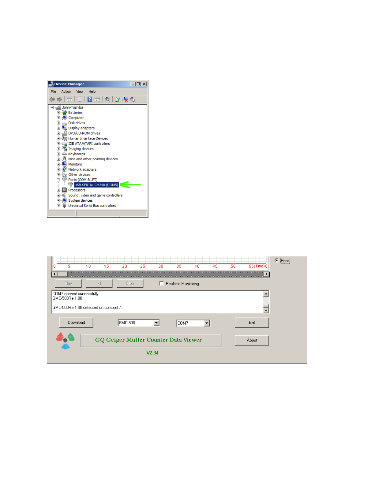
Verify USB driver installation in Windows
Once the GMC-500/GMC-500+ is connected to a computer, from the device manger, you should
see which COM port is assigned to the unit . See the example below. Windows assigned COM3 to
the GMC-500 unit in this example.
For the data viewer or the data logger software, selecting COM5 will establish the connection to the
GMC-500 Geiger counter for the above example
9
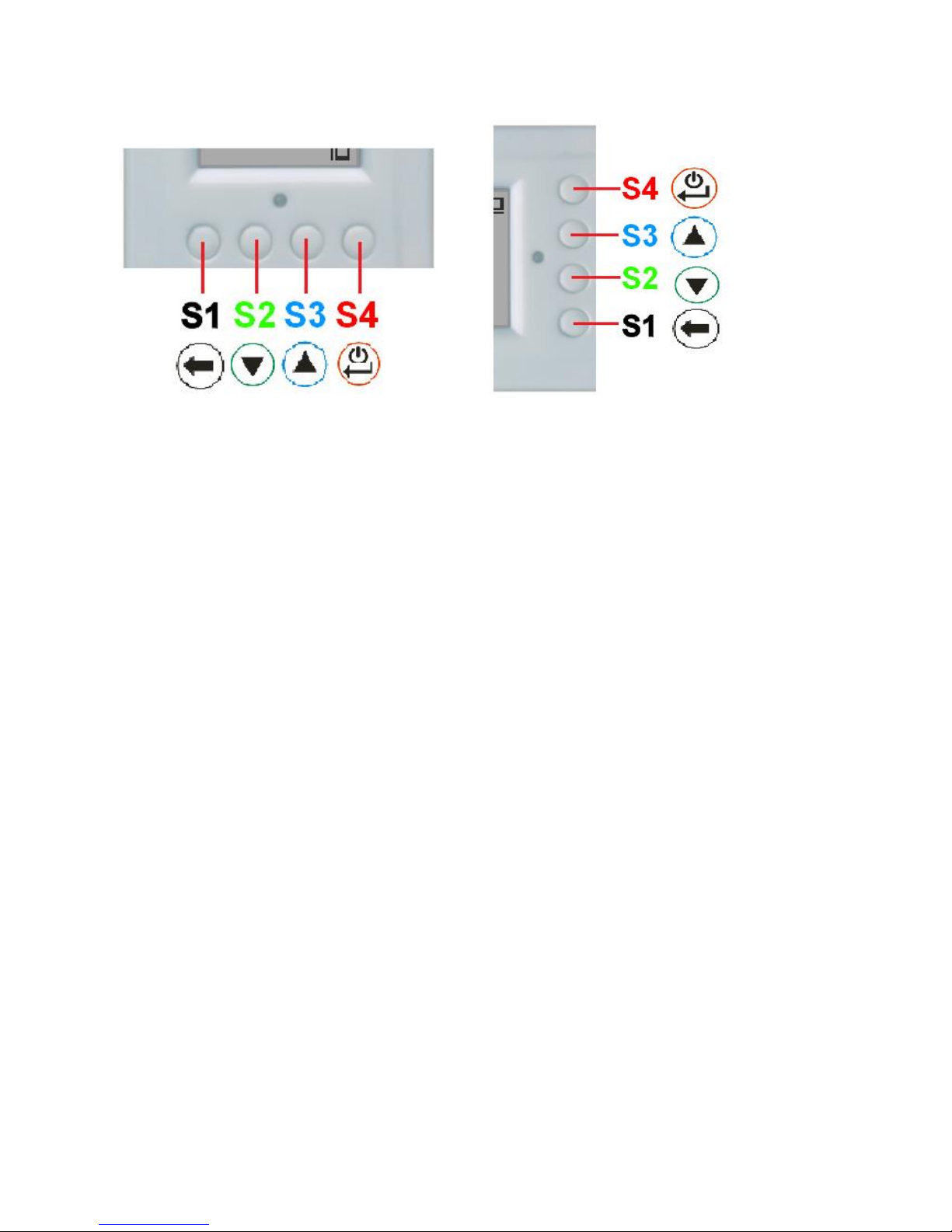
GQ GMC Geiger Counter Multi-Function Keys
The multi-function keys S1,S2,S3 and S4 explained:
Vertical Display Mode Horizontal Display Mode
These key’s function will be reassigned dynamically based on the context of the current (sub-) menu
being displayed.
S1 key
1. There are three display modes: Text, Large Font and Graphic mode.
Pressing the S1 key toggles between these modes.
2. In the menu screen, pressing the S1 key will exit the current menu and will return
back one menu level.
3 In the data input mode, pressing the S1 key will delete the last character entered.
S2 key
1. In text mode, pressing the S2 key will change the text information format.
2. In graphic mode, the S2 key will increase the graphic ZOOM factor.
3. In menu mode, the S2 key acts as the UP key to move the highlight menu item upwards.
4. In the menu mode, while a popup message box is opened, the S2 key changes the
value by cycling through the predefined values.
S3 key
1. In text mode, pressing the S3 key will change the displayed date/time selection.
2. In graphic mode, the S3 key will decrease the graphic ZOOM factor.
3. In menu mode, the S3 key acts as the DOWN key to move the highlight menu item
downwards.
4. In the menu mode, while a popup message box is opened, the S3 key changes the value by
cycling through the predefined values.
S4 key
1. In power off state, only the S4 key acts as the power switch. Holding it for 3 seconds will
power up he unit.
2. In power on state, holding S4 key for 3 seconds will switch the unit off.
3. In menu mode, S4 is the “Confirm”, “Select”, “Enter” key
Power saving mode
The units factory default power saving mode is ON. In this mode, the unit will turn off the display
after 30 seconds idle time. It turns on the LCD display when any key is pressed.
10
Popup Windows
The Popup Windows will show the current status/value of selected features. The current
status/value can be changed only when it is displayed in the Popup Window and the currently
displayed status/value will be stored when the Popup Window has timed out after 3 seconds if no
key has been pressed.
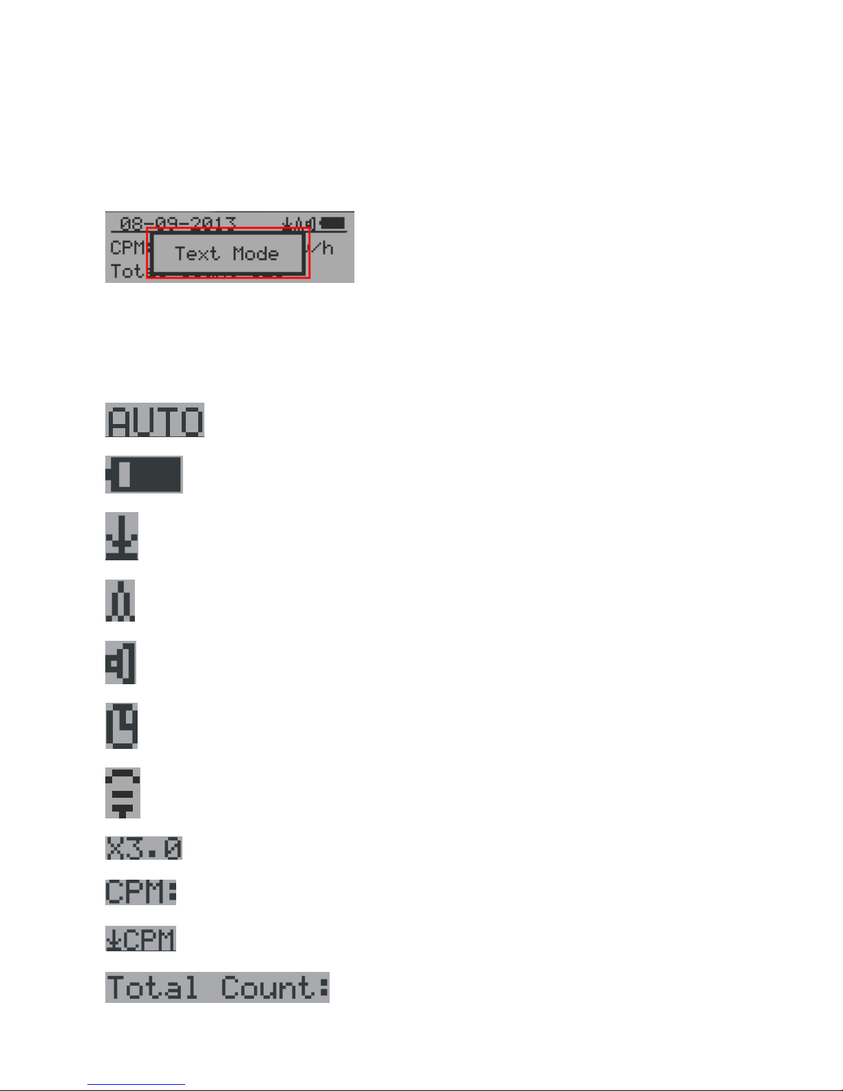
Graphic User Interface (GUI)
Graphic Icons:
Graphic ZOOM factors: 0.5, 1.0, 2.0, AUTO
Battery Status.
Data saving enabled / (History data)
Alarm enabled
Sound enabled
Timed Count. It flashes if timed count in progress.
WiFi Connection
Current graphic ZOOM factor
Current CPM reading
History CPM reading
Total count since power on OR reset/clear.

11
Average CPM of a specific time frame.
Maximum CPM since power on.
Current radiation level is normal.
Current radiation level is medium.
Current radiation level is high.

12
Dual Display Modes
GMC-500 supports two display formats to fit user’s display preferences: Vertical Display and
Horizontal Display.
With the Horizontal Display, the user can select one information screen from: Text, Graphic, Large
Font or Menu. The Vertical Display Mode displays Large Font mode..
Vertical Display Horizontal Display
Horizontal Displays

13
Display Modes
There are four ways to display the information, Text Mode, Large Font Mode , Graphic Mode and
Timed Count
Graphic Mode:
Current radiation level reading in CPM format (Counts Per Minute)
CPS(Count Per Second) in last 60 seconds.
Text Mode:
, Current date and time (Press S3 for toggling
between date and time)
Current radiation level reading in CPM
Current radiation level in µSv/h or
mR/h format

14
Total count.
Total cumulated radiation dose in mR since
power on.
Total cumulated radiation dose in uSv since
power on.
Elapsed time since power on
(Press S2 for toggling displayed info)
Maximum CPM since power on
Average CPM since power on.
Navigation keys for both modes:
S1: Text/Graphic Display Mode Selection
S2: µSv/h, mR/h, Total Count, Elapsed Time selection
S3: Date or Time on title selection
S4: Menu
Large Font Mode:
, Current date and time (Change it in Text Mode)
S2 key toggles between CPM, µSv/h and mR/h mode
Navigation keys:
S1: Text/Graphic/Large Font Display Mode Selection
S2: µSv/h, mR/h, CPM selection
S3: µSv/h, mR/h, CPM selection
S4: Menu
NOTE: Large Font Mode is available in firmware Ver. 2.20 or later only

15
Menu Display
Main Menu
Navigation keys:
S1: Back S2: Up S3: Down S4: Select/Enter
User Option
Navigation keys:
S1: Back S2: Up S3: Down S4: Select/Enter
Alarm Set
Currently the CPM alarm mode is selected
The audio alarm will be triggered once the radiation level reaches the
preset alarm threshold.

16
Date and Time setting
Navigation keys:
S1: Back/Exit
S2: Increase value by 1 (or hold the key down )
S3: Decrease value by 1 1 (or hold the key down)
S4: Select setting mode between Year, Month, Date, Hour, Minute and Second.
Each key press will change the mode to be set.
NOTE: Setting of Date and Time is important, all history data use Date and Time as a time
stamp reference.
NOTE: you need to set the seconds to let unit complete the date & time setup.
Data Saving Setting

17
Selecting this item will turn on/off the real time data saving from followings:
OFF -> Every Second ->Every Minute -> Every Hour->Every Second Threshold->Every Minute
Threshold
NOTE: The history data memory will be used as a ring buffer. Once the end of the
memory is reached, the oldest data will be over written. Carefully select the
data saving interval to save memory space.
With Threshold saving mode, data only will be logged if it exceed the threshold value.
Threshold Data Saving Setting
Select threshold type you want to use: CPM, uSv OR mR
Add Note or Add Location for data saving
The user may add a note with up to 16 characters into the history data to identify the measurement
or location.
This note/location information will be saved together with the radiation data.

18
Note/Location Input
The cursor indicates the position of current character input.
Navigation keys:
S1: Backspace and erase
S2: Move cursor right
S3: Move cursor left
S4: Exit & Store
Erase Saved History Data
Use S2 and S3 to select Yes or No on the screen to confirm the request. After about 3 seconds with
Yes confirmation, the unit will start to erase entire saved history data. It may take a few seconds to
complete the task.
Display Option
Swivel Display Option
Pressing the S4 key will cycle between: Normal -> Swivel -> Auto Swivel modes
In the Auto Swivel mode, the display will be rotated by 180° if the unit is held upside down.

19
WiFi Setup and Check
The WiFi tested with 802.11 n , 802.11 g/n, ,802.11 b/g/n under WPA2-PSK (AES), WEP,
WPAWPA2-PSK (TKIP/AES) and Open security modes.
Select WiFi On/Off item will turn the WiFi connection On/Off
Make sure the WiFi SSID and Password have been set.
Note: All WiFi settings available from GQ GMC Data Viewer Windows software for easier and
faster setup.
WiFi IP address
WiFi Mac address
WiFi Signal Level Checking

20
Internet Data Server Setting
This menu setup is mainly for a data logging server. The unit data can be logged to a server
automatically via WiFi internet HTTP connection.
Here is the default website server setup for: www.gmcmapcom
Website server
User is able to change the server name to point to another http server.
URL for Website server
The default web server data receiving URL is log2.asp.
User is able to change the URL to user specific URL. However, the URL data parameters in a fixed
format.
Example:
http://www.GMCmap.com/log2.asp?AID=0230111&GID=0034021&CPM=15&ACPM=13.2&uSV
=0.075
Website server User ID
Each data submission has a user ID. The user ID is the user account ID from the data server. It will
send to server with the data to log.
This is an example user ID from www.gmcmap.com

21
Website server Geiger Counter ID
Each data submission has a Geiger Counter ID. The Geiger Counter ID is a unique ID in data server
database. It will send to server with the data to log.
This is an example Geiger Counter ID from www.gmcmap.com
WiFi Data Logging Period
The default data logging period is 2 minutes. This will let unit to log the data to website server every
two minute.
User is able to change the period from 1 to any minutes.
WiFi Data Logging Testing
User can test the server settings anytime to confirm the server settings are working.
The result will be either Successful or Link Server Failed.
Note: All Server settings available from GQ GMC Data Viewer Windows software for easier
and faster setup.

22
Calibrate the reading
You do not need to do the calibration if you just want to qualitatively detect radiation.
However, if you have standard radiation sources with known µSv/h value, you may calibrate
the instrument to get accurate readings.
The factory default calibration value is for general in-door and out-door measurements.
Calibration
Select Calibrate form the Main Menu. There are three points provided for calibration.
Each calibration point needs two values to be entered, the CPM value and the µSv/h value.
The user can enter up to three calibration points from large to high count rates.
Procedure:
1. Place the testing radiation source ~30mm away to the center of unit Geiger Tube side. In
Text or Graphic mode, wait for at least 3 minutes.
2. Note the CPM value.
3. Select Calibrate menu item on the device, then input both the CPM value you noted and the
known µSv/h value of the calibration source.
4. Wait for the popup window to close to save the data for this calibration point.
5. Continue with step 1 with other calibrated radiation sources.
Navigation keys:
S1: Back/Exit
S2: Increase the value by 10 CPM or 0.1uSv/h respectively
S3: Decrease the value by 1 CPM or 0.01uSv/h respectively
S4: Toggle input data type between CPM and uSv/h

23
Factory reset
Select Factory Reset to reset the unit to the factory default settings.
Note: The reset will erase all user settings and recorded history data.
Procedure:
Select Factory Reset menu item and change the popup Windows message to Yes. Wait for popup
message window’s timeout to confirm the reset request. Any other key press will cancel the reset
request. It may take up to 30 seconds to complete the reset.
Battery Status
Select Battery submenu and Battery item for checking the current battery voltage.
Battery Type

24
Select different battery type to match the installed battery type.
Power saving mode
Pressing the S4 key will toggle the Power Saving mode ON and OFF.
In power saving mode, the units LCD display will be turned off after 30 seconds if no key is pressed
to save battery power. The audio signal will not be turned off if it has been set to ON.
The LCD back light will be off during the power saving mode.
Pressing any key will active the LCD backlight again.
The unit movement does not weak up the unit if the motion detection is OFF.
Motion Detection
GMC-500 has motion detection feature. It can detect unit movement, upside down, single tap and
double tap. Turn off the motion detection disables all motion related features.
Reset Total Count

25
The Reset Total Count menu item let user to clear the total count on main text mode screen.
This may be used before a fixed time count measurement start.
Gyroscope Data Display
The internal digital accelerometer is able to provide real-time gyroscope data. It displays current unit
X,Y,Z axis data and detected motion event. Such as single tap OR double tap.
Communication Baud Rate
This Geiger counter serial communication baud rate is selectable from following value:
1200,2400,4800,9600,14400,19200,28800, 38400,57600,115200. Press S4 key changes baud rate.
The new baud will take immediate effect. The new value also be saved and used on next power up.
Reverse Display
Contrast Adjustment

26
Use S2 and S3 to adjust the contrast level. The contrast level will be saved and it will be used when
the unit is ON.
Timed Count
The Timed Count can be started with a schedule OR without a schedule.
When it started with a schedule, the Timed Count will be started after a scheduled time period passed.
This is useful if a testing target is not ready immediately.
When it started without a schedule, the Timed Count will be started immediately once the timed
count period is set.
The Timed Count can be set from the menu:
Set a schedule
This example shows the schedule is set to 2 minute.
Navigation keys:
S1: Back/Exit
S2: Increase the cursor position value
S3: Decrease the position value.
S4: Move the cursor to input data type between Day, Hour, Minute and Second.
Set Timed Count Duration
There are 5 preset durations from menu: 1 minutes, 10 minutes, 100 minutes, 12 Hours and 24 Hours.
If the duration is not listed, then you can set a new duration (1 second to 256 days) from menu Other
duration:

27
This example shows a 2 days duration is set for Timed Count.
Navigation keys:
S1: Back/Exit
S2: Increase the cursor position value
S3: Decrease the position value.
S4: Move the cursor to input data type between Day, Hour, Minute and Second.
Start a Timed Count
If no Schedule set, then the Timed Count starts immediately after the duration set.
If the Schedule is set, then the Timed Count will be started after a scheduled time period passed.
This is useful if a testing target is not ready immediately.
Once the Timed Count schedule is active, the Timer icon will be showed on the top icon area.
When the Timed Count started, the screen will pop up a message: Timed Count Started.
The Timed Count can be cancelled anytime.
Now you can exit the menu and see the Timed Count progress screen and information:

28
About
This menu item is used to gather information about the instruments model number, firmware
revision and serial number.
Model information
Firmware version
Unit serial number

29
GQ GMC Data Viewer Software
The GQ MGC Data Viewer software is a utility software comes with the GMC-500 package.
Main features:
- Download the history data from GMC-500
- Real time monitoring with graphic when it connected with GMC-500
- Save the history data in .bin OR .csv MS Excel format.
- Synchronize the data and time to GMC-500 with computer’s data and time
- User defined automatic date and time synchronization period.
- GQ Terminal feature provide a detailed communication protocol exercise interface.

30
WiFi Setup Utility
With Data Viewer software Settings menu, users are able to quick and easily setup the device WiFi
connection and data logging.

31
GQ Terminal
The GQ Terminal provides an immediate access interface to the GMC-500 communication protocol.
Followings are click to send commands in software, for not listed commands user can type into the
command box of software:
GETVER, GETSERIAL, GETCPM, KEY0, KEY1, KEY2, KEY3, SPEAKER0, SPEAKER1,
ALARM0, ALARM1, GETVOLT, GETGYRO, GETCFG, GETCPS, GETTEMP, HEARTBEAT0,
HEARTBEAT1, GETDATETIME, CFGUPDATE, POWEROFF, POWERON, SETDATETIME,
FACTORYRESET
For detailed communication protocol commands, please see:
http://www.gqelectronicsllc.com/downloads/download.asp?DownloadID=62
An optional software is the GQ GMC Data Logger PRO. It is a generic software for different brand
and model Geiger Counters. It has much more advanced features for advanced users.
See download page for the demo version.

32
Online Geiger Counter World Map
www.GMCmap.com
The Geiger Counter World Map is free and open protocol map. Anyone can use it for free. It
provides a free space to all Geiger Counter users.
As a registered user, each user can have multiple Geiger Counters at different locations. All
registered Geiger Counters have free history data storage space. User is able to retrieve their
history data anytime, anywhere. User is able to publish their history data to others by set the data
properties.
Software
The GMCmap accepts any software automatically submitted data.
The following tested software are free for automatic submit data feature.
1. GQ Geiger Counter Data Logger PRO (works on all Geiger Counter)
2. GQ Geiger Counter Data Viewer (works on GMC-300, GMC-320, GMC-500 series Geiger
Counters)
Both software can be found and downloaded from GQ Electronics LLC download page
The GMC-500 series is able to submit the data via internal WiFi connection without other software.
Auto Submit Data Protocol
In order to use automatically submit data, user has to be registered from GMCmap.com, so that to
get a valid user account ID and Geiger Counter ID. Each user can have multiple Geiger Counters at
the different locations.
Auto submit data url format:

33
http://www.GMCmap.com/log.asp?id=UserAccountID+GeigerCounterID+CPM+ACPM+uSV
At least one reading data has to be submitted.
Here: 1. UserAccountID: user account ID. This ID is assigned once a user registration is completed.
2. GeigerCounterID: a global unique ID for each registered Geiger Counter. 3. CPM: Count Per
Minute reading from this Geiger Counter . 4. ACPM: Average Count Per Minute reading from this
Geiger Counter(optional). 5. uSv: uSv/h reading from this Geiger Counter(optional).
Followings are valid data submission examples:
1. http://www.GMCmap.com/log.asp?id=0230111+0034021+15+13.2+0.075
2. http://www.GMCmap.com/log.asp?id=0230111+0034021+15+13.2+0
3. http://www.GMCmap.com/log.asp?id=0230111+0034021+15+0+0
4. http://www.GMCmap.com/log.asp?id=0230111+0034021+0+13.2+0
5. http://www.GMCmap.com/log.asp?id=0230111+0034021+0+0+0.075
The result will be returned immediately.
The following are the returned result examples:
1. OK.
2. Error! User is not found.
3. Error! Geiger Counter is not found.
4. Warning! The Geiger Counter location changed, please confirm the location.
If a location change warning received, the user need to confirm the location from that Geiger
Counter profile. OR Create another Geiger Counter from your account. In this case, you can have
two locations share one Geiger Counter.
Applications
Stationary Application
The unit has two holes on its back for hanging the unit on the wall for stationary monitoring of
radiation and long term surveillance applications. With the wall adapter, it is able to monitor the
data continuously, 24/7.
Mobile Application
To use the unit n the car while driving, use a car USB power adapter to charge/power the unit.
Position the unit where it can easily detect radiation, i.e. on the dashboard or similar locations in the
car. You may need to fix the unit to an appropriate location for safety reasons.

34
Other technical details you may want to know
Data Port
This model has a 3.5mm analog data output port. It uses standard 3.5mm audio stereo plug, This port
is not for the earphone. The audio signal is for third party device and software. The signal can be
connected to other devices or computer microphone port directly.
USB Port
The USB port is the standard mini-USB port. It is used for data communication, external power and
the battery charger connection.
Data collection time
The GMC-500 radiation data is collected continuously, and every second the measured data is
being transmitted to the CPU for processing.
Extend battery operating time
Turn on the Power Saving mode to extend the battery operating time. Turn off the speaker if it is
not necessary. If a fully charged battery run-out in less than 5 operating hours, then the battery
needs to be replaced. Use a standard 18650 (18 x 65.0 mm) rechargeable Li-ion battery.
The GMC-500 will operate normally when a non-rechargeable battery is installed. Select the battery
type to none rechargeable battery from the unit menu.
Third party software developers
The GMC-500 is an open application protocol product. Users are able to develop their own software
based on the published GQ-RFC1201 protocol. We encourage you to share your generic software
with other users. Please contact support@gqelectronicsllc.com if you have any questions.
You can find the GQ-RFC1201 protocol at the software download page.
http://www.gqelectronicsllc.com/comersus/store/download.asp
 Loading...