

Page 1
Mainboard User’s Manual
Notice:
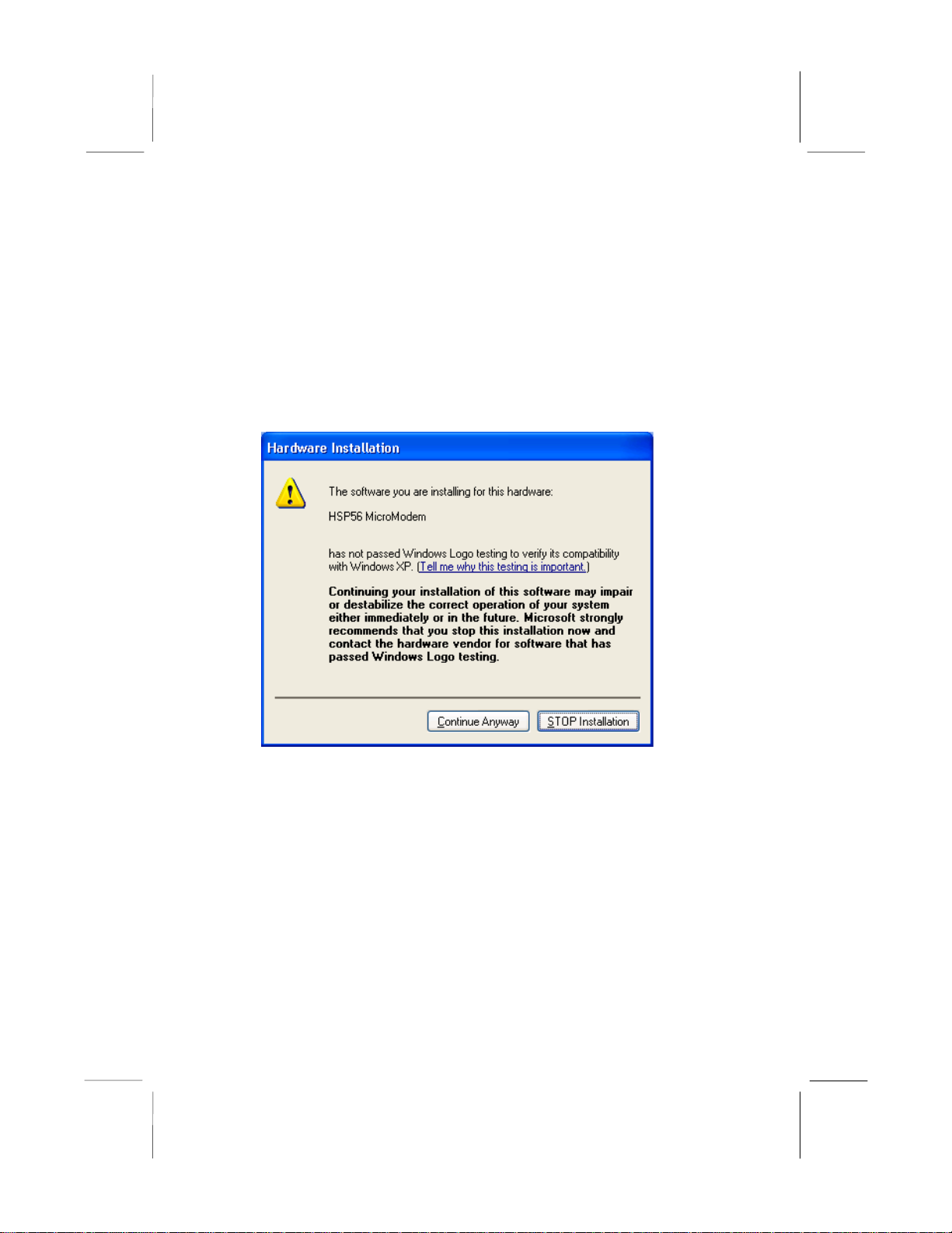
Owing to Microsoft’s certifying schedule is various to every
supplier, we might have some drivers not certified yet by
Microsoft. Therefore, it might happen under Windows XP that a
dialogue box (shown as below) pop out warning you this software
has not passed Windows Logo testing to verify its compatibility
with Windows XP. Please rest assured that our RD department has
already tested and verified these drivers. Just click the “Continue
Anyway” button and go ahead the installation.
II
Page 2

Mainboard User’s Manual
Getting started.
This chapter describes the procedure for unpacking your new
computer system and accessories.
Unpacking your system
-Place the computer box flat on the floor.
-Place your feet on either of the system unit box
-Carefully life the system unit out of the box. Lift the unit slowly
and evenly until it is completely removed from the box, then set it
on a flat surface.
-Set the system unit in the location where you intend to use it.
Ensure that the location is well ventilated and out of sunlight.
-Save the system unit box and packing material in the event you
need to move or ship the system in the future.
Setting up your new computer
After you unpack your new system and verify that all hardware has
been received undamaged, you are ready to connect the system
components if they are not already connected. Please follow the
procedure set below.
Connecting a keyboard and mouse
-Plug the keyboard cable into your computer’s keyboard connector.
-Plug the mouse cable into your computer’s mouse connector.
Connecting the monitor
-Make sure the monitor is turned off.
-If the monitor cable is not connected to the monitor, make this
connection now.
-Connect the other end of the monitor cable to your computer’s
monitor connector.
-Plug the monitor into an AC outlet.
III
Page 3

Mainboard User’s Manual
Connecting the power cable
-Connect the supplied power cord to the power connector on the
back of the system unit.
-Connect the other end to a grounded AC outlet, power strip, surge
protector, or uninterruptible power supply.
Powering-on your system
The electrical power used to power your computer and other AC
appliances is not always steady and continuous. Often, there are
bursts of energy called surges or spikes that occur on the line.
These spikes can cause damage your computer and all attached
peripherals. In fact, if just one device is not protected, a spike can
travel through that unprotected device to all of the peripherals
attached to it. For that reason, we recommend you use an
uninterruptible power supply to protect your computer and all
peripherals against damage caused by spikes.
What if nothing happens?
In the unlikely event that your computer does not power on:
-Make sure the power cables are securely connected to the AC
source and the power connector on the back of the computer.
-If you are using a power strip, surge protector, or uninterruptible
power supply, make sure it is connected to a functioning AC
source and is turned on.
-Make sure the AC outlet is not controlled by a wall switch that
may be turned off.
-If you suspect the AC outlet is faulty, plug an appliance that you
know is working(such as a lamp) into the outlet and turn on the
appliance. If the appliance works, the outlet is working.
If you can hear the power supply fan working, but nothing appears
on the monitor, make sure the monitor:
-Is connected to a functioning AC outlet,
-Is attached to the appropriate connector on the back of your
computer.
-Is turned on.
IV
Page 4

Mainboard User’s Manual
-Has its brightness control set at a reasonable level. If this control
is set too low, it may cause a black image to appear on the monitor.
Opening up your system and changing or upgrading system
-Antistatic grounding: Your computer contains many sensitive
components that are prone to damage from static electricity. A
static-electric charge is present in your body. Your body can pick
up static electricity especially in carpeted rooms and in dry
weather.
When you body touches an object with an opposite charge, the
static electricity is discharged and you feel a “shock.” This shock
can severely damage your computer’s components. Even mild
static shock can damage the sensitive electronics of your computer.
Therefore, before you touch the inside of your computer, touch a
metal part on the outside of the computer several times to remove
the static-electric charge from your body. In addition, avoid
touching any exposed integrated circuitry or connectors inside your
computer or individual components installed in your computer.
To further reduce the chance of danger from static electricity, wear
a grounding strap around your wrist
When upgrading your computer, never let loose metal parts remain
in your computer. If you accidentally drop a screw or a paper clip
in the system, remove it before turning on your computer. If a
metal part is touching any part of the circuit boards in the system, it
can cause a short-circuit, which may damage the computer. To
minimize the chance of loose parts entering your computer, do not
remove parts from their antistatic bag until you are ready to use
them.
Looking at the insides of your computer
The system board (or motherboard) is the large, flat board inside
you computer. The system board accommodates most of the
important parts of your computer, such as microprocessor,
memory, and the expansion slots.
V
Page 5

Mainboard User’s Manual
The power supply looks like a silver cube at the back of the system
unit. The back of the power supply has a small red voltage slide
switch on the back, which is accessible at the rear of the system
unit. If you use your computer in the US only, the power setting
on the back of the power supply should be set at 115. If your
power supply does not have this switch, you will not need to do
anything. Do not change the setting of this switch unless it shows
something besides 115. .
Your computer uses Dual Inline Memory Modules (DIMMs).
DIMMs are available in many configurations and the
specifications. Before you add RAM, be sure you obtain the
appropriate DIMMs for your computer’s system board. In
addition, refer to the manual that came with the system board to
see whether the system board has certain rules, such as where the
added RAM is to be installed.
To install DIMMs
-Turn off your computer and remove the back and side panels
-Hold the DIMM above the socket.
-Install the DIMM vertically into the socket. Apply equal pressure
on each end of the DIMM
-Make sure the clamps on both sides of the socket have locked the
DIMM into place. The DIMM should be standing straight up.
To remove DIMMs:
-Turn off your computer and remove the back and side panels
-Gently push down the tab securing the DIMM in the socket. The
DIMM pops out of the socket.
-Lift the DIMM straight up from the socket and remove it gently.
**Never forcibly remove a DIMM, and never try to remove a
DIMM without first releasing it from the socket. Otherwise, you
may break the DIMM and the socket.
VI
Page 6

Mainboard User’s Manual
Installing a new hard drive
-Turn off your computer and remove the back and side panels.
-Put the new hard drive into place and screw in to ensure it will not
fall out of system
-Configure one of the drives as the master and the other as the
slave. Typically, the boot drive is configured as the master. The
selection of master/slave typically is done using a jumper on the
drive. Refer to the manual that came with the new drive and the
one installed in your computer for more information.
-Connect one end of the 40-pin (or 80-pin) ribbon cable from the
IDE controller to the back of the new drive
-Connect the 4-pin cable from the power supply to the back of the
new drive
Installing a second CD-ROM drive
-Turn off your computer and remove the back and side panels.
-Insert the new cd-rom drive in an available 5 ¼-inch drive bay
below the first cd-rom drive
-Secure the new cd-rom into place
-Connect the 40-pin (or 80-pin) ribbon cable from the IDE
connector on the motherboard to the back of the new cd-rom drive
-Connect the 4-pin cable from the power supply to the back of the
new cd-rom drive
VII
Page 7

Mainboard User’s Manual
Table of Contents
Trademarks.............................................................................. I
Notice .....................................................................................II
Getting Started.......................................................................III
Chapter 1: Motherboard Introduction..............................................1
Key Features............................................................................2
Package Contents.....................................................................5
Chapter 2: Mainboard Installation...................................................6
Mainboard Components ..........................................................7
I/O Ports...................................................................................7
Install Memory ........................................................................8
Setting Jumper Switches..........................................................9
Install the Mainboard.............................................................10
Optional Extension Brackets .................................................11
Install Other Devices .............................................................12
Expansion Slots .....................................................................15
Chapter 3: BIOS Setup Utility.......................................................17
Introduction ...........................................................................17
Running the Setup Utility......................................................18
Standard CMOS Setup Page..................................................19
Advanced Setup Page............................................................21
Power Management Setup Page ............................................25
PCI/Plug and Play Setup Page...............................................24
Load Optimal Settings...........................................................29
Load Best Performance Settings............................................29
Features Setup Page...............................................................25
CPU PnP Setup Page.............................................................27
Hardware Monitor Page.........................................................28
Change Password...................................................................28
Exit .......................................................................................29
Chapter 4: Software & Applications..............................................35
Introduction ...........................................................................35
Installing Support Software...................................................31
Bundled Software Installation...............................................33
Technical Support..........................................................................34
Linux/Windows Issue............................................................34
Power/Printer/Video/Monitor issue.......................................36
Sound/Speaker/Modem issue ................................................37
Contact Information............................................................... 39
VIII
Page 8

1: Introduction
Chapter 1
Motherboard Introduction
This mainboard supports VIA Samuel2 1Giga Pro processor with
front-side bus speeds of 133MHz.
This mainboard has the SiS630E chipset, and integrates a 3D
Graphics Accelerator and Ultra DMA 33/66/100 function. The
mainboard has a built-in AC97 Codec, provides an AMR (Audio
Modem Riser) slot to support Audio and Modem application, and
has a built-in 10BaseT/100BaseTX Network Interface. In
addition, the mainboard has an extended set of ATX I/O Ports
including PS/2 keyboard and mouse ports, two USB ports, a
parallel port, a VGA port, a serial port, a game port and audio
ports. An extra USB header gives you the option of connecting two
more USB ports.
This mainboard has all the features you need to develop a powerful
multimedia workstation. The board is Micro ATX size and has a
power connector for an ATX power supply.
1
Page 9

Mainboard User’s Manual
Key Features
The key features of this mainboard include:
1Giga Pro Processor
♦ Built-in 1Giga Pro CPU
♦ Supports up to 133MHz Front-Side Bus
Memory Support
♦ Two DIMM slots for 168-pin SDRAM memory modules
♦ Support for 100/133 MHz memory bus
♦ Maximum installed memory is 2 x 512MB = 1.0GB
Expansion Slots
♦ One AMR slot for a special audio/modem riser card
♦ Three 32-bit PCI slots for PCI 2.2-compliant bus interface.
Onboard IDE channels
♦ Primary and Secondary PCI IDE channels
♦ Support for PIO modes, Bus Mastering and Ultra DMA
33/66/100 modes
Power Supply and Power Management
♦ ATX power supply connector
♦ ACPI and previous PMU support, suspend switch
♦ Supports Wake on LAN and Wake on Alarm
Built-in Graphics System
♦ Onboard 64-bit 2D/3D video/graphics accelerator
♦ Supports tightly coupled 64 bits 100Mhz host interface to
VGA to speed up GUI performance and video playback
frame rate
♦ Shared system memory area up to 64MB
♦ Supports up to 2048x2048 Texture Size
2
Page 10

1: Introduction
AC’97 Codec: VT1612A
♦ Compliant with AC’97 2.1 specification
♦ Three Audio Jacks – Line-Out, Line-In and Microphone-In
♦ Sound Blaster, Sound Blaster Pro Compatible
♦ Digital I/O compatible with consumer mode S/PDIF
♦ Advanced power management support
Built-in Ethernet LAN (Optional)
♦ 10BaseT/100BaseTX Ethernet LAN
♦ LAN controller integrates Fast Ethernet MAC and PHY
compliant with IEEE802.3u 100BASE-TX, 10BASE-T and
ANSI X3.263 TP-PMD standards
♦ Compliant with ACPI 1.0 and the Network Device Class
Power Management 1.0
♦ High Performance provided by 100Mbps clock generator
and data recovery circuit for 100Mbps receiver
Onboard I/O Ports
♦ Provides PC99 Color Connectors for easy peripheral device
connections
♦ Floppy disk drive connector with 1Mb/s transfer rate
♦ One serial ports with 16550-compatible fast UART
♦ One parallel port with ECP and EPP support
♦ Two USB ports, and optional two USB ports module
♦ Two PS/2 ports for keyboard and mouse
♦ One infrared port connector for optional module
Hardware Monitoring
♦ Built-in hardware monitoring for CPU & System
temperatures, fan speeds and mainboard voltages
Onboard Flash ROM
♦ Automatic board configuration support Plug and Play of
peripheral devices and expansion cards
3
Page 11

Mainboard User’s Manual
Bundled Software
♦ PC-Cillin2000 provides automatic virus protection under
Windows 98/ME/NT/2000/XP
♦ MediaRing Talk provides PC to PC or PC to Phone
internet phone communication
♦ 3Deep delivers the precise imagery and displays accurate
color in your monitor
♦ Recovery Genius 21
st
V5.0 provides the function to
recover, reserve and transfer hard disk data.
♦ CD Ghost is the software stimulating a real CD-ROM to
perform equivalent function.
♦ Language Genius 21
st
is the software to provides learning
tools of language and singing.
♦ PC DJ is a dual-MP3 player that enables users to actually
mix music right on their own personal computers.
♦ Adobe Acrobat Reader V5.0 is the software to help users
read .PDF files.
Dimensions
♦ Micro ATX form factor (24.4cm x 19cm)
4
Page 12

1: Introduction
Package Contents
Your complete system shipped with the following accessories:
This User’s Guide
1 IDE cable (already installed)
1 Floppy disk drive cable (already installed)
Support software on CD-ROM disk
1 Keyboard
1 Mouse
1 Set of stereo speakers
Static Electricity Precautions
Components of this system can be damaged by static electricity.
Please take the following precautions when unpacking and
installing the system.
1. Keep the mainboard and other components in their original
static-proof packaging until you are ready to install them.
2. During installation, wear a grounded wrist strap if possible. If
you don’t have a wrist strap, discharge static electricity by
touching the bare metal of the system chassis.
3. Handle the mainboard carefully by the edges. Avoid touching
the components unless it is absolutely necessary. During
installation put the mainboard on top of the static-protection
packaging it came in with the component side facing up.
5
Page 13

2: Mainboard Installation
Chapter 2
Mainboard Installation
To install this mainboard in a system, follow the procedures in this
chapter:
Identify the mainboard components
Install a CPU
Install one or more system memory modules
Verify that any jumpers or switches are set correctly
Install the mainboard in a system chassis (case)
Connect any extension brackets or cables to the mainboard
connector headers
Install any other devices and make the appropriate connections
to the mainboard connector headers.
Note:
1. Before installing this mainboard, make sure jumper JP7 set to
Normal setting. See this chapter for information on locating
JP7 and the setting options.
2. Never connect power to the system during installation. Doing
so may damage the mainboard.
6
Page 14
2: Mainboard Installation
Mainboard Components
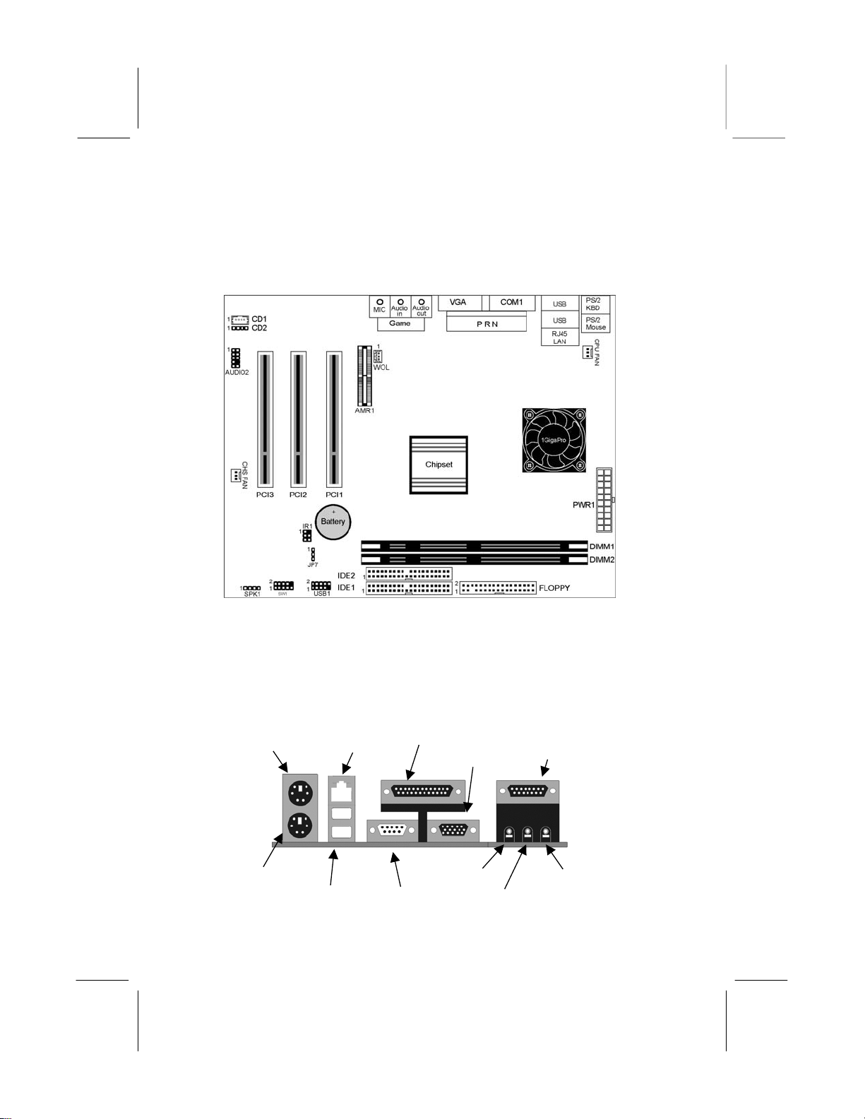
This diagram identifies major components on the mainboard.
Note: Any jumpers on your mainboard that do not appear in
this illustration are for testing only.
I/O Ports
The illustration below shows a side view of the built-in I/O ports
on the mainboard.
PS/2 Mouse
PS/2 Keyboard
USB Ports
LAN Port
Parallel Port
Line-Out Jack
Serial Port COM1/3
VGA Port
Line-In Jack
Game/MIDI Port
Microphone Jack
7
Page 15
Mainboard User’s Manual
Install Memory
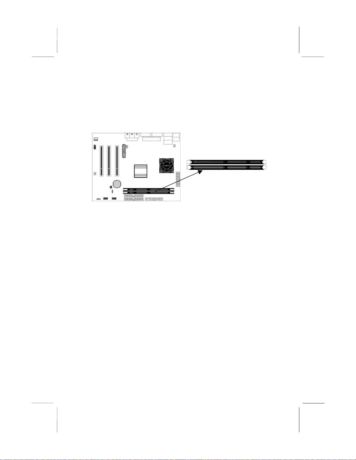
The mainboard has two DIMM sockets for system memory
modules. You must install at least one memory module in order to
use the mainboard.
DIMM1
DIMM2
For this mainboard, you must use 168-pin, 3.3V unbuffered PC100
or PC133 SDRAM memory modules. You can install any size
memory module from 32 MB to 512 MB, so the maximum
memory size is 2 x 512 MB = 1 GB.
The edge connectors on the memory modules have cut outs, which
coincide with spacers in the DIMM sockets so that memory
modules can only be installed in the correct orientation.
To install a module, push the retaining latches at either end of the
socket outwards. Position the memory module correctly and insert
it into the DIMM socket. Press the module down into the socket so
that the retaining latches rotate up and secure the module in place
by fitting into notches on the edge of the module.
8
Page 16
2: Mainboard Installation
Setting Jumper Switches
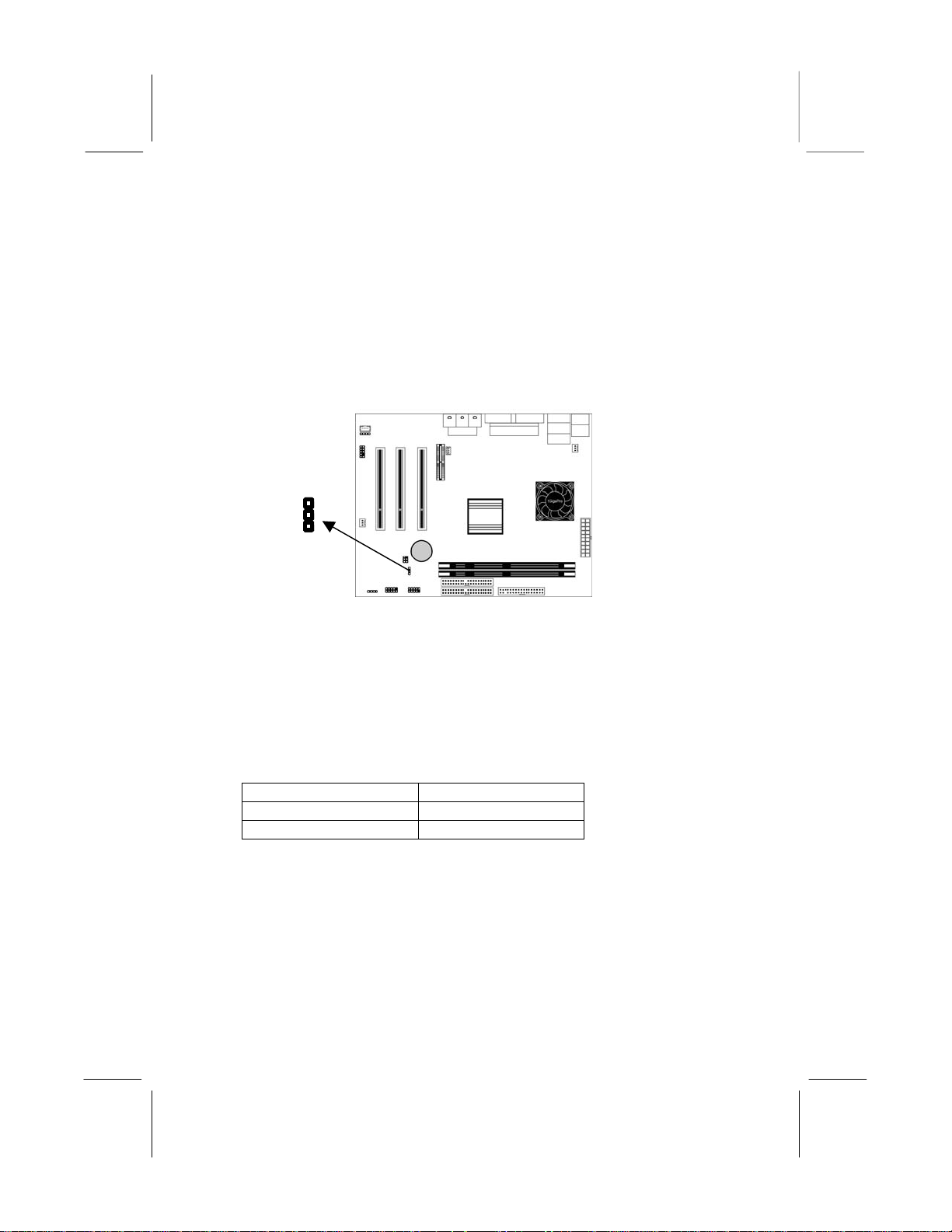
Jumpers set system configuration options. Jumper caps connect
jumper pins and change the way of the mainboard’s operation by
changing the electronic circuits. Connecting two pins with a
jumper cap makes SHORT pins; removing a jumper cap from two
pins makes OPEN.
1
JP7
Jumper JP7: Clear CMOS Memory
Use this jumper to clear the contents of the CMOS memory. You
may need to clear the CMOS memory if the settings in the Setup
Utility are incorrect and prevent your mainboard from operating.
To clear the CMOS memory, disconnect all the power cables from
the mainboard and then move the jumper cap into the CLEAR
setting for a few seconds.
Function Jumper Setting
Normal Operation Short Pins 1-2
Clear CMOS Memory Short Pins 2-3
9
Page 17
Mainboard User’s Manual
Install the Mainboard
Install the mainboard in a system chassis (case). The board is a
micro ATX size mainboard with a twin-tier of I/O ports. Ensure
that your case has an I/O cover plate that matches the ports on this
mainboard.
Install the mainboard in a case. Follow the instructions provided by
the case manufacturer using the hardware and internal mounting
points on the chassis.
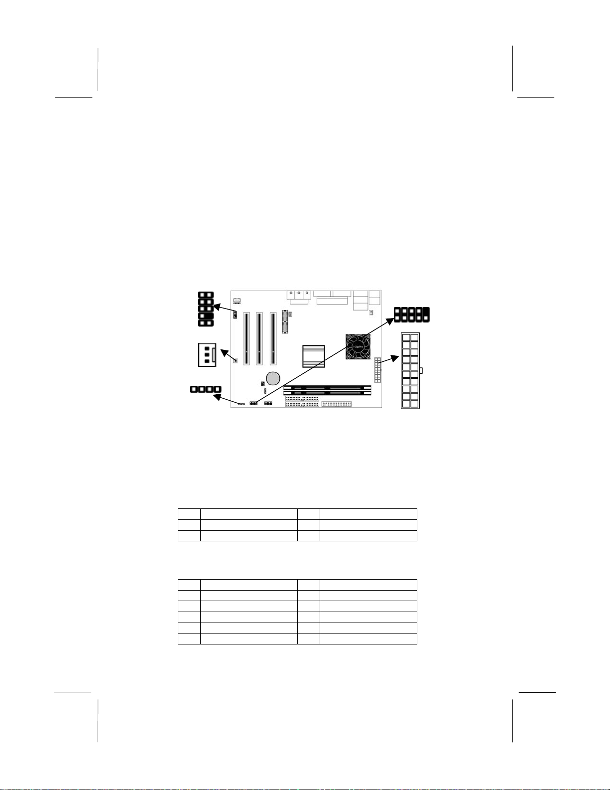
AUDIO2
CHS FAN
SPK1
SW1
PWR1
Connect the power connector from the power supply to the PWR1
connector on the mainboard.
If there is a cooling fan instal led in the system chassis, connect the
cable from the cooling fan to the CHS FAN fan power connector
on the mainboard.
Connect the cable from the PC speaker to the SPK1 header on the
mainboard.
Pin Signal Pin Signal
1 SPKR 2 NC
3 GND 4 +5V
Connect the case switches and indicator LEDs to the SW1 header.
Here is the list of SW1 pin assignment.
Pin Signal Pin Signal
1 HDD LED 2 POWER(ACPI) LED
3 HDD LED 4 POWER(ACPI) LED
5 RESET SWITCH 6 POWER BUTTON
7 RESET SWITCH 8 POWER BUTTON
9 RSVD_DNU 10 KEY
10
Page 18
2: Mainboard Installation
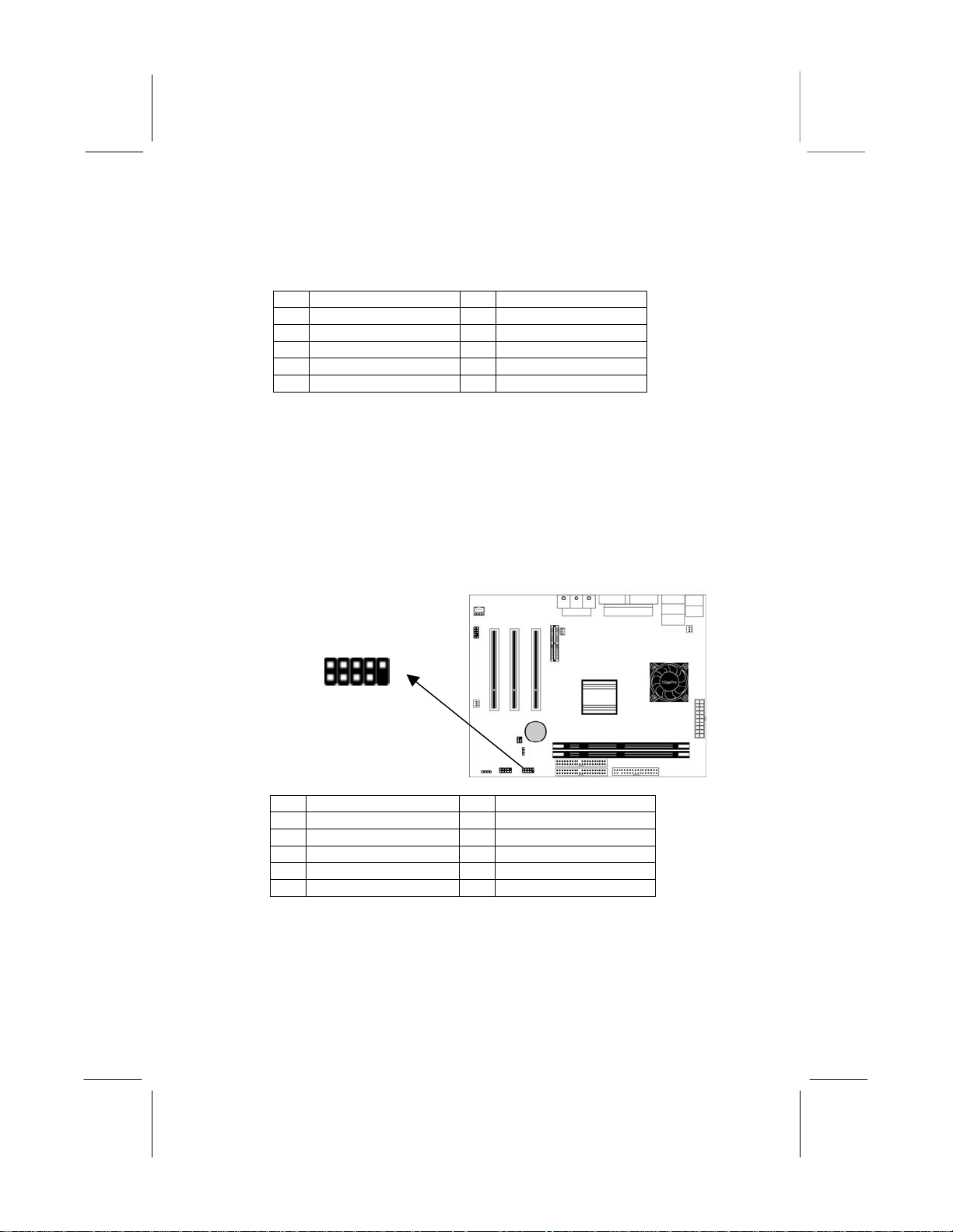
If there are a headphone jack or/and a microphone jack on the front
panel, connect the cables to the AUDIO2 header on the mainboard.
Here is the list of AUDIO2 pin assignment.
Pin Signal Pin Signal
1 MIC 2 GND
3 MIC-P 4 VCC
5 FPOUT-R 6 RET-R
7 NC 8 KEY
9 FPOUT-L 10 RET-L
Optional Extension Brackets
For this mainboard, you can also obtain a USB module extension
bracket. Install them by following the steps below.
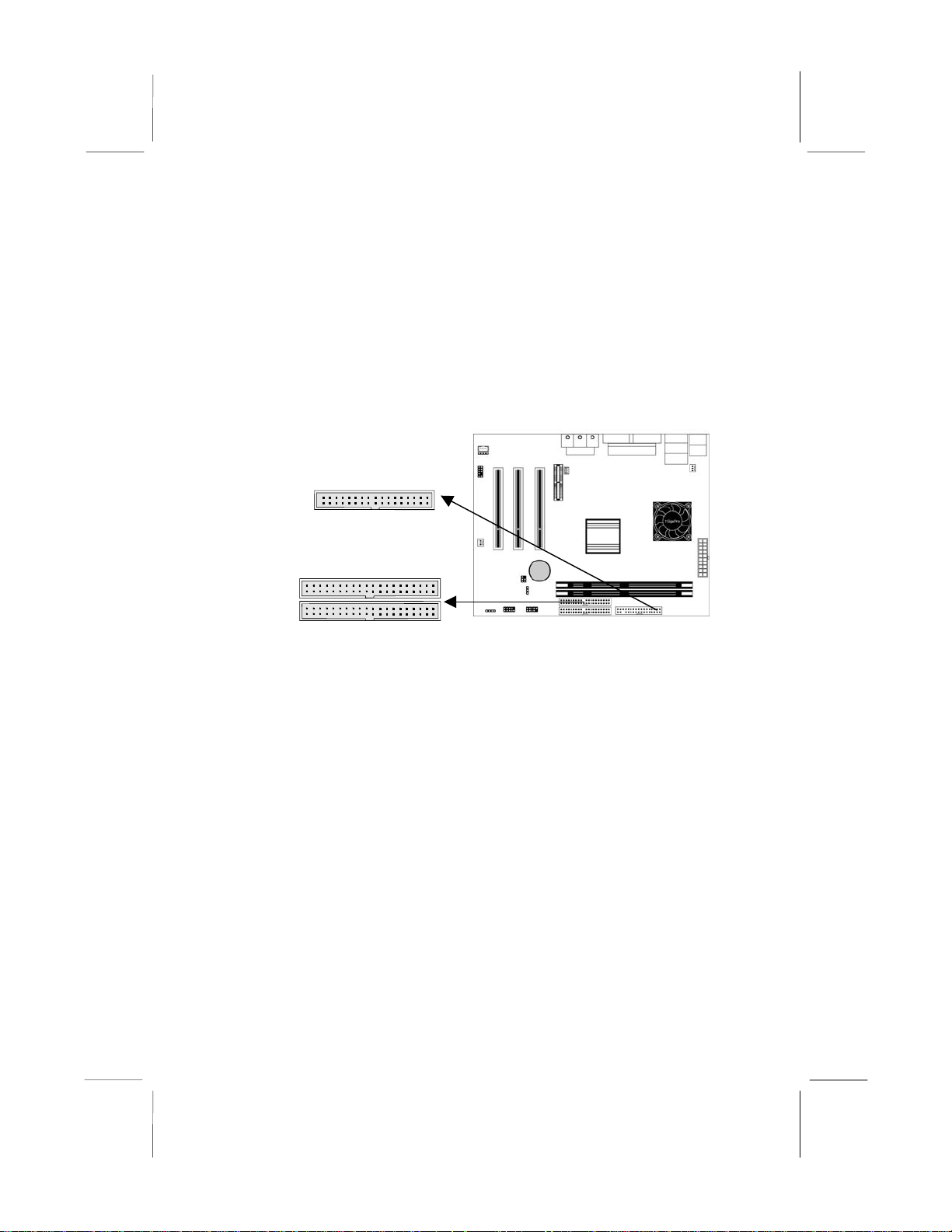
Extended USB Module
This module bracket has two USB ports for more USB devices
(USB port 3-4).
USB1 Header
1
Pin Signal Pin Signal
1 VERG_FP_USBPWR0 2 VERG_FP_USBPWR0
3 USB_FP_P0- 4 USB_FP_P15 USB_FP_P0+ 6 USB_FP_P1+
7 GROUND 8 GROUND
9 KEY 10 USB_FP_OC0
1. Locate the USB1 header on the mainboard.
2. Plug the bracket cable onto the header.
11
Page 19
Mainboard User’s Manual
2
3. In the system chassis, remove a slot cover from one of the
expansion slots and install the extension bracket in the
opening. Use the screw that held the slot cover in place to
secure the extension bracket to the chassis.
Install Other Devices
Install and connect any other devices in the system following the
steps below.
FLOPPY
1
IDE
1
1
Floppy Disk Drive
The mainboard ships with a floppy disk drive cable that can
support one or two drives. Drives can be 3.5” or 5.25” wide, with
capacities of 360K, 720K, 1.2MB, 1.44MB, or 2.88MB.
Install your drives and connect power from the system power
supply. Use the cable provided to connect the drives to the floppy
disk drive header FLOPPY.
IDE1
12
Page 20
2: Mainboard Installation
IDE Devices
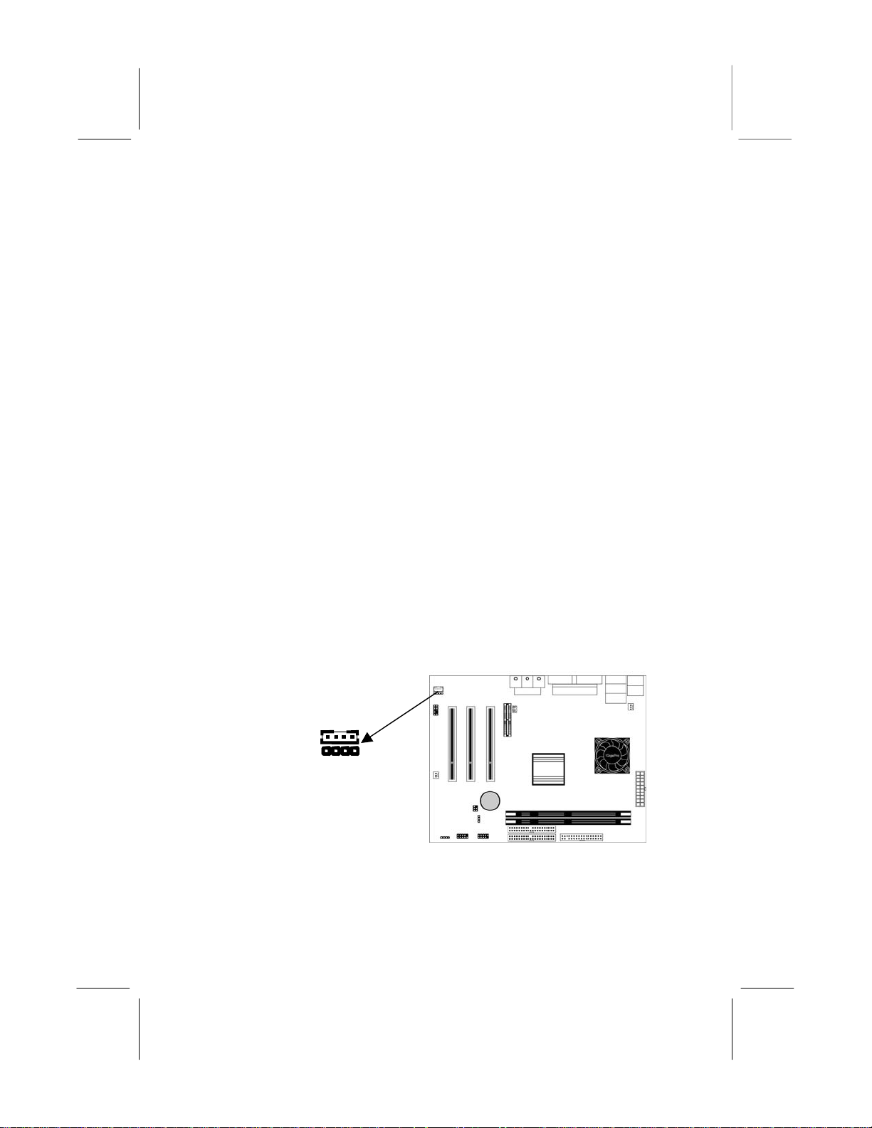
IDE devices include hard disk drives, high-density diskette drives,
and CD-ROM or DVD-ROM drives, among others.
The mainboard ships with an IDE cable that can support one or two
IDE devices. If you connect two devices to a single cable, you
must configure one of the drives as Master and one of the drives as
Slave. The documentation of the IDE device will tell you how to
configure the device as a Master or Slave device. The Master
device connects to the end of the cable.
Install the device(s) and connect power from the system power
supply. Use the cable provided to connect the device(s) to the
Primary IDE channel connector IDE1 on the mainboard.
If you want to install more IDE devices, you can purchase a second
IDE cable and connect one or two devices to the Secondary IDE
channel connector IDE2 on the mainboard. If you have two
devices on the cable, one must be Master and one must be Slave.
Internal Sound Connections
If you have installed a CD-ROM drive or DVD-ROM drive, you
can connect the drive audio cable to the onboard sound system.
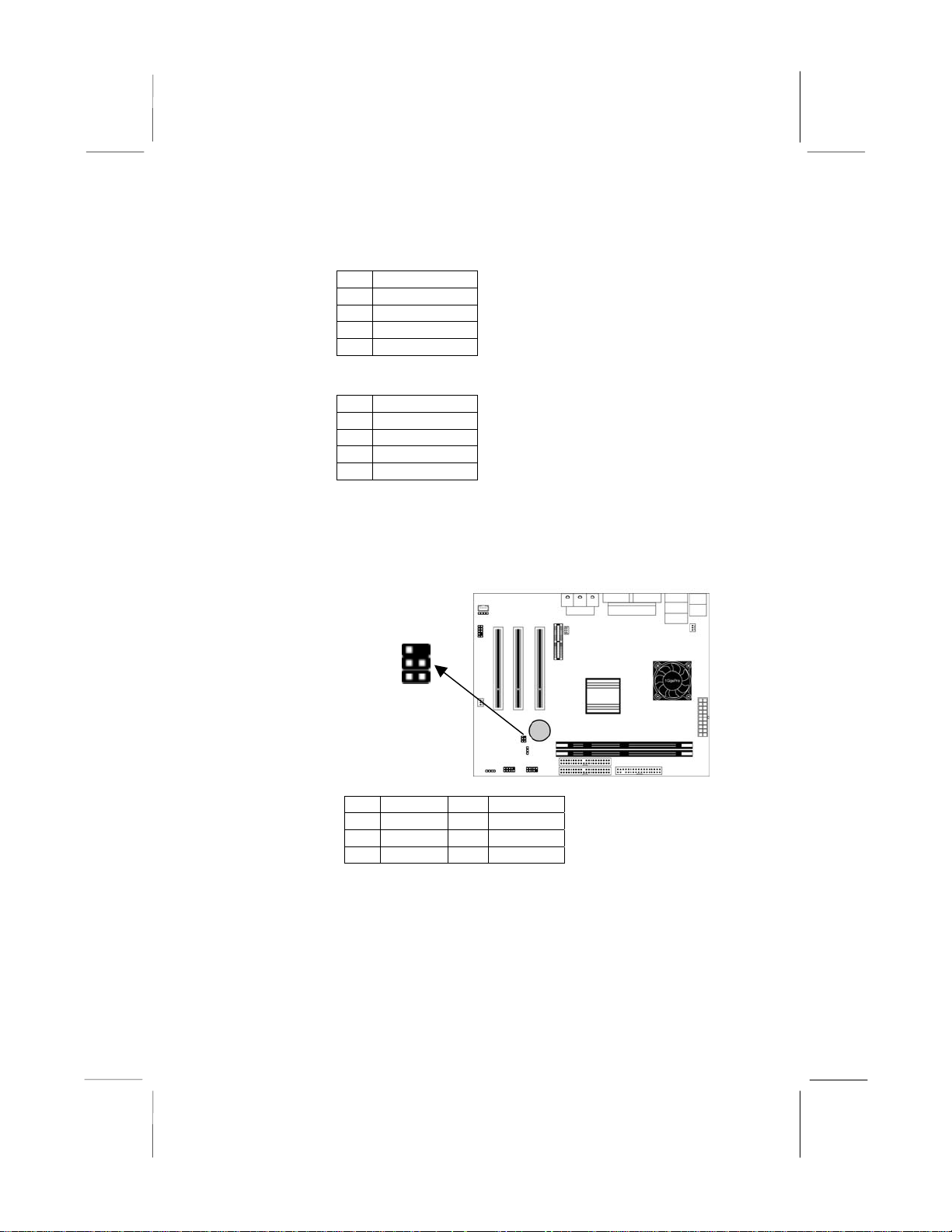
On the mainboard, locate the two 4-pin connectors CD1 and CD2.
There are two kinds of connector because different brands of CDROM drive have different kinds of audio cable connectors.
Connect the cable to the appropriate connector.
CD1
CD2
13
Page 21
Mainboard User’s Manual
CD1
Pin Signal
1 GND
2 CD IN R
3 GND
4 CD IN L
CD2
Pin Signal
1 CD IN L
2 GND
3 GND
4 CD IN R
Infrared Port
You can connect an infrared port to the mainboard. You can
purchase this option from third-party vendors.
1
IR1 Header
Pin Signal Pin Signal
1 NC 2 KEY
3 +5V 4 GND
5 IRTX 6 IRRX
1. Locate the infrared port IR1 header on the mainboard.
2. If you are adding an infrared port, connect the ribbon cable
from the port to the header and then secure the port to an
appropriate place in your system chassis.
14
Page 22
2: Mainboard Installation
A
Expansion Slots
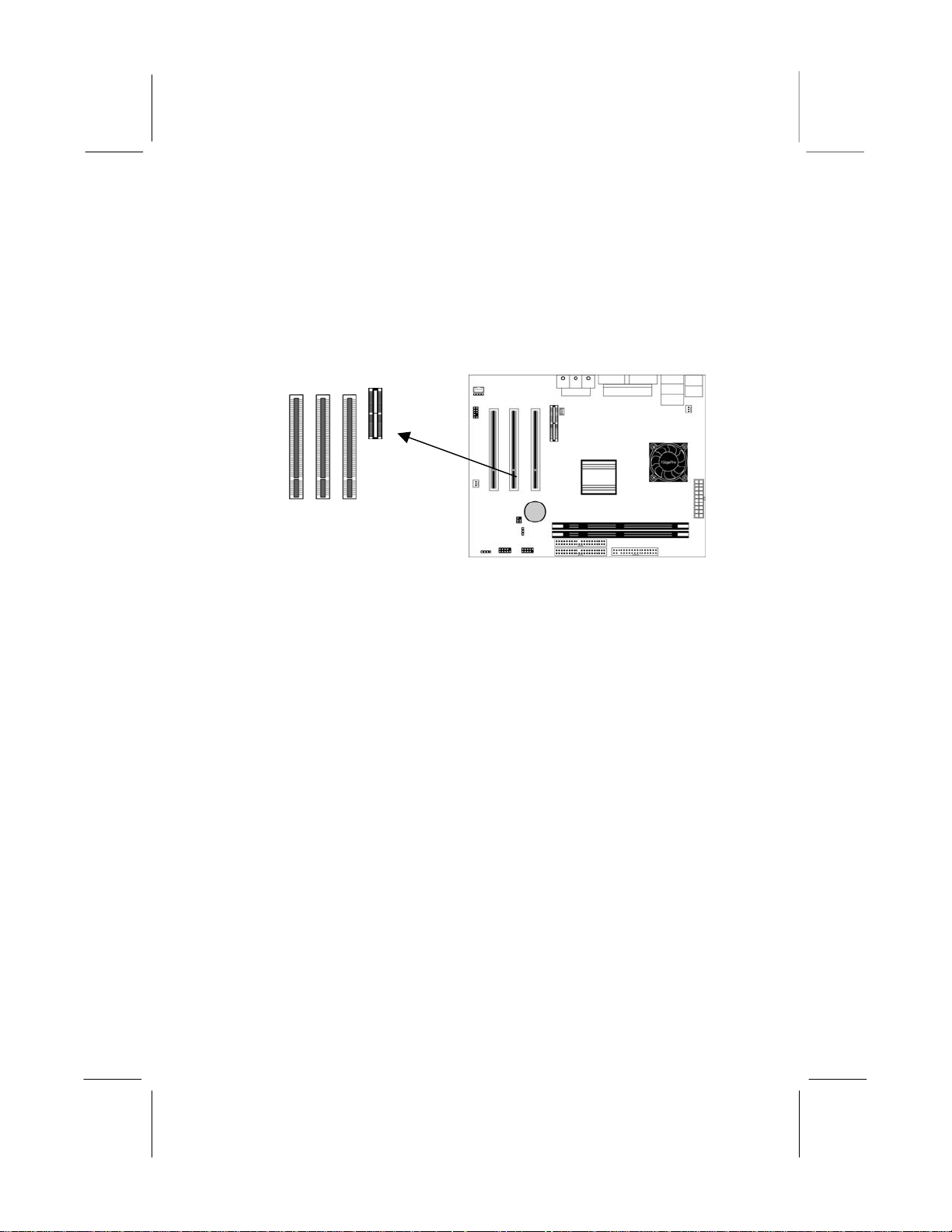
This mainboard has one AMR and three 32-bit PCI expansion
slots.
PCI3 PCI1
MR1
PCI2
Follow the steps below to install a PCI/AMR expansion card.
1. Locate the AMR or PCI slots on the mainboard.
2. Remove the slot cover for this slot from the system chassis.
3. Insert the expansion card edge connector into the slot and press
it firmly down into it so that it is fully inserted.
4. Secure the expansion card bracket to the system chassis using
the screw that held the slot cover in place.
AMR Slot
The AMR (Audio Modem Riser) slot is an industry standard slot
that allows for the installation of a special audio/modem riser card.
Different territories have different regulations regarding the
specifications of a modem card. You can purchase an AMR card
that is approved in your area and install it directly into the AMR
slot.
15
Page 23
Mainboard User’s Manual
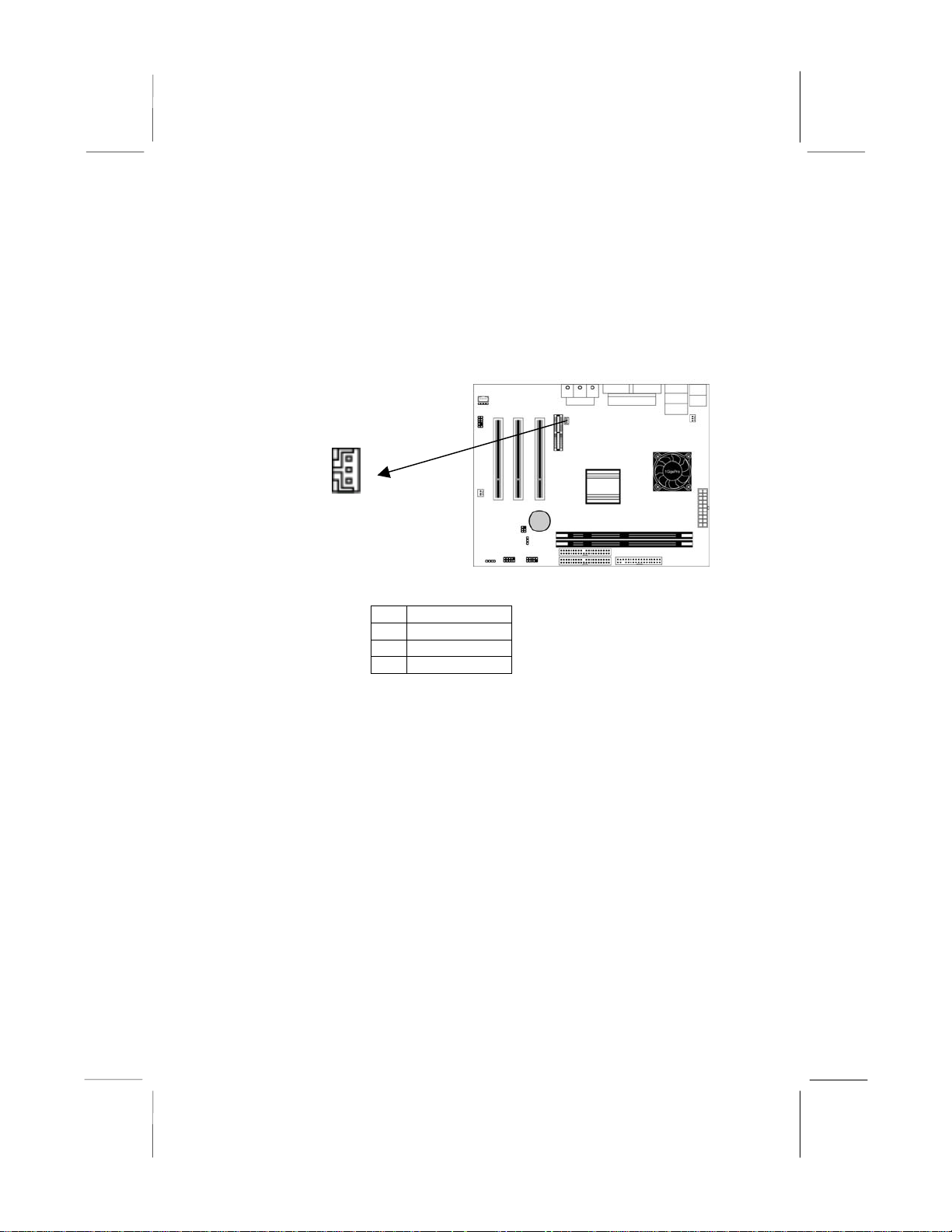
Wake On LAN (WOL)
If you have installed a LAN adapter expansion card, connect the
card to the Wake On LAN connector WOL1. This allows
incoming traffic to resume the system from a software power
down. You need to enable this feature in the system setup utility.
WOL1
Header
Pin Signal
1 5VSB
2 GND
3 -RING
16
Page 24

4: Software & Applications
Chapter 3
BIOS Setup Utility
Introduction
The BIOS Setup Utility records settings and information about
your computer, such as date and time, the type of installed
hardware and various configuration settings. Your computer
applies the information to initialize all the components when
booting up and basic functions of coordination between system
components.
If the Setup Utility configuration is incorrect, it may cause the
system to malfunction. It can even stop your computer booting
properly. If it happens, you can use the clear CMOS jumper to
clear the CMOS memory which has stored the configuration
information, or you can hold down the Page Up key while
rebooting your computer. Holding down the Page Up key also
clears the setup information.
You can run the setup utility and manually change the
configuration. You might need to do this to configure some
hardware installed in or connected to the mainboard, such as the
CPU, system memory, disk drives, etc.
`
17
Page 25
Mainboard User’s Manual
Running the Setup Utility
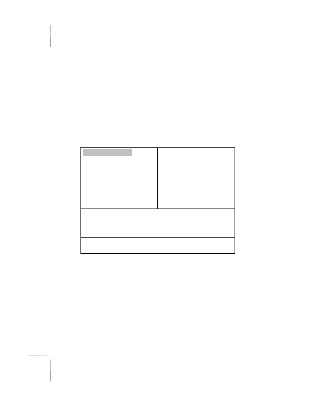
Each time you start your computer, a message appears on the
screen before the operating system loading that prompts you to
“Hit <DEL> if you want to run SETUP”. Whenever you see this
message, press the Delete key, and the Main menu page of the
Setup Utility appears on your monitor.
AMIBIOS SIMPLE SETUP UTILITY – VERSION 1.21.06
(C) 2000 American Megatrends, Inc. All Rights Reserved
Standard CMOS Setup
Advanced Setup
Power Management Setup
PCI / Plug and Play Setup
Load Optimal Settings
Load Best Performance Settings
Esc : Quit ↑ ↓ ← →: Select Item (Shift)F2 : Change Color
F5 : Old Values
F6 : Optimal values F7 : Best performance values
F10 : Save&Exit
Standards COMOS setup for changing time, date, hard disk type,
Features Setup
CPU PnP Setup
Hardware Monitor
Change Password
Exit
etc.
You can use the cursor arrow keys to highlight any of the options
on the main menu page. Press Enter to select the highlighted
option. To leave the setup utility, press the Escape key. To cycle
through the Setup Utility’s optional color schemes hold down the
Shift key and press F2.
Some of the options on the main menu page lead to tables of items
with installed values. In these pages, use the cursor arrow keys to
highlight the items, and then use the PgUp and PgDn keys to cycle
through the alternate values for each of the items. Other options on
18
Page 26

4: Software & Applications
the main menu page lead to dialog boxes that require you to answer
Yes or No by hitting the Y or N keys.
If you have already made changes to the setup utility, press F10 to
save those changes and exit the utility. Press F5 to reset the
changes to the original values. Press F6 to install the setup utility
with a set of default values. Press F7 to install the setup utility with
a set of high-performance values.
19
Page 27
Mainboard User’s Manual
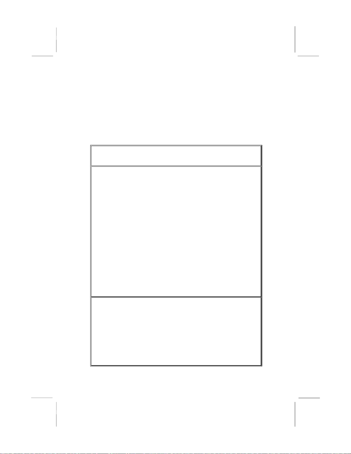
Standard CMOS Setup Page
Use this page to set basic information such as the date, the time,
the IDE devices, and the diskette drives. If you press the F3 key,
the system will automatically detect and configure the hard disks
on the IDE channels.
AMIBIOS SETUP – STANDARD CMOS SETUP
(C) 2000 American Megatrends, Inc. All Rights Reserved
Date (mm/dd/yy) : Wed May 8, 2002
Time (hh/mm/ss) : 11:01:00
LBA Blk PIO 32Bit
Type Size Cyln Head WPcom Sec
Mode Mode Mode Mode
Pri Master : Auto
On
Pri Slave : Auto
On
Sec Master : Auto
On
Sec Slave : Auto
On
Floppy Drive A : 1.44 MB 3 1/2
Floppy Drive B : Not Installed
Month : Jan – Dec
ESC : Exit
Day : 01 – 31
↑↓ : Select Item
Year : 1901 – 2099
PU/PD/+/- : Modify
(Shift)F2 : Color
20
Page 28
4: Software & Applications
F3 : Detect All HDD
Date &
Use these items to set the system date and time
Time
Pri Master
Pri Slave
Sec Master
Sec Slave
Floppy
Use these items to configure devices connected to
the Primary and Secondary IDE channels. To
configure an IDE hard disk drive, choose Auto. If the
Auto setting fails to find a hard disk drive, set it to
User, and then fill in the hard disk characteristics
(Size, Cyls, etc.) manually. If you have a CD-ROM
drive, select the setting CDROM. If you have an
ATAPI device with removable media (e.g. a ZIP
drive or an LS-120) select Floptical.
Use these items to set the size and capacity of the
floppy diskette drive(s) installed in the system.
Drive A
Floppy
Drive B
Advanced Setup Page
Use this page to set more advanced information about your system.
Take some care with this page. Making changes can affect the
operation of your computer.
AMIBIOS SETUP – ADVANCED SETUP
(C) 2000 American Megatrends, Inc. All Rights Reserved
Share Memory Size 16MB
st
1
Boot Device
Floppy
nd
2
Boot Device IDE-0
rd
3
Boot Device
CDROM
21
Page 29
Mainboard User’s Manual
Try Other Boot Devices
Yes
S.M.A.R.T. for Hard Disks
Disabled
BootUp Num-Lock On
Floppy Drive Swap
Disabled
Floppy Drive Seek
Disabled
PS/2 Mouse Support
Enabled
Password Check Setup
Boot To OS/2 > 64MB No
Internal Cache
Enabled
System BIOS Cacheable
Disabled
CAS Latency 3T
Share
Memory
Size
1st Boot
Device
nd
Boot
2
Device
rd
Boot
3
Device
Try Other
Boot Device
S.M.A.R.T.
for Hard
Disks
BootUp
This item lets you allocate a portion of the main
memory for use by the onboard VGA display.
Use these items to determine the device order the
computer uses to look for an operating system to
load at start-up time.
If you enable this item, the system will also search
for other boot devices if it fails to find an operating
system from the first two locations.
Enable this item if any IDE hard disks support the
S.M.A.R.T. (Self-Monitoring, Analysis and Reporting
Technology) feature.
This item determines if the Num Lock key is active
ESC : Quit ↑↓←→ :
Select Item
F1 : Help
PU/PD/+/- : Modify
F5 : Old Values
(Shift)F2 : Color
F6 : Load Optimal values
F7 : Load Best performance
values
22
Page 30

Num-Lock
Floppy
Drive Swap
4: Software & Applications
or inactive at system start-up time.
If you have two diskette drives installed and you
enable this item, drive A becomes drive B and drive
B becomes drive A.
23
Page 31

Mainboard User’s Manual
Floppy
Drive Seek
PS/2 Mouse
Support
Password
Check
Boot to
OS/2 >
64MB
Internal
Cache
System BIOS
Cacheable
CAS
Latency
If you enable this item, your system will check all
floppy disk drives at start up. Disable this item
unless you are using an old 360KB drive.
If this item is set to Enabled, the onboard PS/2
Mouse port will work. Setting this to Disable turns off
the port.
If you have entered a password for the system, use
this item to determine, if the password is required to
enter the Setup Utility (Setup) or required both at
start-up and to enter the Setup Utility (Always).
Enable this item if you are booting the OS/2
operating system and you have more than 64MB of
system memory installed.
Leave these items enabled since all the processors
that can be installed on this board have internal
cache memory.
If you enable this item, a segment of the system
BIOS will be cached to main memory for faster
execution.
This item determines the operation of the SDRAM
memory CAS (column address strobe). We
recommend that you leave this item at the default
value. The 2T setting requires faster memory that
specifically supports this mode.
24
Page 32
4: Software & Applications
p
Power Management Setup Page
This page sets some of the parameters for system power
management operation.
AMIBIOS SETUP – POWER MANAGEMENT SETUP
(C) 2000 American Megatrends, Inc. All Rights Reserved
Power Management/APM
APM/ACPI Standby Time
Out<Minute> Disabled
Suspend Time Out<Minute>
Disabled
Hot Key Power On
Disabled
Onboard LAN Power On
Disabled
Ring On Power On
Disabled
RTC Alarm Power On
Disabled
RTC Alarm Date 15
RTC Alarm Hour 12
RTC Alarm Minute
30
RTC Alarm Second
00
ESC : Quit ↑↓←→ :
Select Item
F1 : Help
PU/PD/+/- : Modify
F5 : Old Values
(Shift)F2 : Color
F6 : Load Optimal values
F7 : Load Best performance
values
Power
Management
Standby
Time Out
Suspend
Use this item to enable or disable a power
management scheme. If you enable power
management, you can use the items below to set
the power management operation. Both APM and
ACPI are supported.
This sets the timeout for Standby mode in
minutes. If the time selected passes without any
system activity, the computer will enter powersaving Standby mode.
This sets the timeout for Suspend mode in
minutes. If the time selected
asses without any
25
Page 33

Mainboard User’s Manual
Time Out
Hot Key
Power On
OnBoard
LAN Power
On
Ring On
Power On
RTC Alarm
Power On
system activity, the computer will enter powersaving Suspend mode.
If you enable this item, you can turn the system on
by pressing hot keys (Ctrl+Alt+BackSpace) on the
keyboard. You must connect an ATX power
supply and enable the jumper in order to use this
feature.
The system can be turned off with a software
command. If you enable this item, the system can
automatically resume if there is traffic on the
network adapter. You must use an ATX power
supply in order to use this feature.
The system can be turned off with a software
command. If you enable this item, the system can
automatically resume if there is an incoming call
on the Fax/Modem. You must use an ATX power
supply in order to use this feature.
The system can be turned off with a software
command. If you enable this item, the system can
automatically resume at a fixed time based on the
system’s RTC (realtime clock). Use the items
below this one to set the date and time of the
wake-up alarm. You must use an ATX power
supply in order to use this feature.
26
Page 34
4: Software & Applications
PCI / Plug and Play Setup Page
This page sets some of the parameters for devices installed on the
PCI bus and devices that use the system plug and play capability.
AMIBIOS SETUP – PCI / PLUG AND PLAY SETUP
(C) 2000 American Megatrends, Inc. All Rights Reserved
Plug and Play Aware O/S
Yes
Primary Graphics Adapter
PCI
Allocate IRQ for PCI VGA Yes
Reserved Memory Size
Disabled
Reserved Memory Address
C8000
ESC : Quit ↑↓←→ :
Select Item
F1 : Help
PU/PD/+/- : Modify
F5 : Old Values
(Shift)F2 : Color
F6 : Load BIOS Defaults
F7 : Load Setup Defaults
Plug and
Play Aware
O/S
Primary
Graphics
Adapter
Allocate IRQ
to PCI VGA
Reserved
Memory Size
Reserved
Memory
Enable this item if you are using an O/S that
supports Plug and Play such as Windows 95 or
98.
This item indicates if the primary graphics adapter
uses the PCI or AGP bus. The default PCI setting
still lets the onboard display work and allows the
use of a second display card installed in a PCI
slot.
If this item is enabled, an IRQ will be assigned to
the PCI VGA graphics system. You set this value
to No to free up an IRQ.
This item lets you reserve a block of memory for
any device that requires it.
This item lets you set the address for any block of
memory that has been reserved.
27
Page 35

Mainboard User’s Manual
Address
28
Page 36
4: Software & Applications
Load Optimal Settings
If you select this item and press Enter a dialog box appears. If you
press Y, and then Enter, the Setup Utility loads a set of fail-safe
default values. These default values are not very demanding and
they should allow your system to function with most kinds of
hardware and memory chips.
Load Best Performance Settings
If you select this item and press Enter a dialog box appears. If you
press Y, and then Enter, the Setup Utility loads a set of fail-safe
default values. These default values are not very demanding and
they should allow your system to function with most kinds of
hardware and memory chips.
Note: It is highly recommended that users enter this option to
load optimal values for accessing the best performance.
Features Setup Page
This page sets some of the parameters for peripheral devices
connected to the system.
AMIBIOS SETUP – PERIPHERAL SETUP
(C) 2000 American Megatrends, Inc. All Rights Reserved
OnBoard FDC
Enabled
OnBoard Serial PortA
3F8h/COM1
OnBoard IR Port
Disabled
29
Page 37
Mainboard User’s Manual
OnBoard Parallel Port
378h
Parallel Port Mode
EPP+ECP
Parallel Port IRQ 7
Parallel Port DMA 3
OnBoard Game Port Auto
OnBoard MIDI Port 300h
MIDI Port IRQ
10
OnBoard PCI IDE Both
Ultra DMA Support
Disabled
On Chip Audio
Enabled
On Chip Modem
Enabled
OnBoard LAN
Enabled
USB Function
Enabled
USB Function for DOS
Disabled
ESC : Quit ↑↓←→ :
Select Item
F1 : Help
PU/PD/+/- : Modify
F5 : Old Values
(Shift)F2 : Color
F6 : Load Optimal values
F7 : Load Best performance
values
30
Page 38

OnBoard FDC
OnBoard
Serial PortA
OnBoard IR
Port
Onboard
Parallel Port
Parallel Port
Mode
Parallel Port
IRQ
Parallel Port
DMA
Onboard PCI
IDE
Ultra DMA
Support
On Chip
Audio
On Chip
Modem
OnBoard
LAN
USB Function
USB Function
for DOS
4: Software & Applications
Use this item to enable or disable the onboard
floppy disk drive interface.
Use this item to enable or disable the onboard
COM1 serial port, and to assign a port address
Use this item to define the protocol for an infrared
port if you have installed an optional IR port. The
choices are IrDA and ASKIR.
Use this item to enable or disable the onboard
LPT1 parallel port, and to assign a port address.
The Auto setting will detect and available address.
Use this item to set the parallel port mode. You
can select SPP (Standard Parallel Port), ECP
(Extended Capabilities Port), EPP (Enhanced
Parallel Port), or ECP + EPP.
Use this item to assign either IRQ 5 or 7 to the
parallel port.
Use this item to assign a DMA channel to the
parallel port. The options are 0, 1 and 3.
Use this item to enable or disable either or both of
the onboard Primary and Secondary IDE
channels.
Use this item to set Ultra DMA support for IDE
devices on the Primary or Secondary IDE
channels. You must enable this or UDMA devices
will not work at their intended speed.
This item enables or disables the onboard audio
chip.
This item enables or disables the onboard modem
chip.
This item enables or disables the onboard network
interface.
Enable this item if you plan to use the USB ports
on this mainboard.
Enable this item if you plan to use the USB ports
on this mainboard in a DOS environment.
31
Page 39
Mainboard User’s Manual
CPU PnP Setup Page
This page lets you manually configure the mainboard for the CPU.
The system will automatically detect the kind of CPU that you
have installed and make the appropriate adjustments to the items
on this page.
AMIBIOS SETUP – CPU PnP SETUP
©2000 American Megatrends, Inc. All Rights Reserved
CPU Type VIA C3
ESC :
Quit ↑↓←→ : Select Item
F1 : Help PU/PD/+/- : Modify
F5 : Old Values (Shift)F2 : Color
F6 : Load Optimal values
F7 : Load Best performance values
CPU Type
Note: If you manually set the wrong speed and the system won’t
run properly, press the Page Up key while the system is booting
and a default setting will replace the incorrect CPU setting.
This item shows the type of CPU that has installed
in your system.
32
Page 40
4: Software & Applications
Hardware Monitor Page
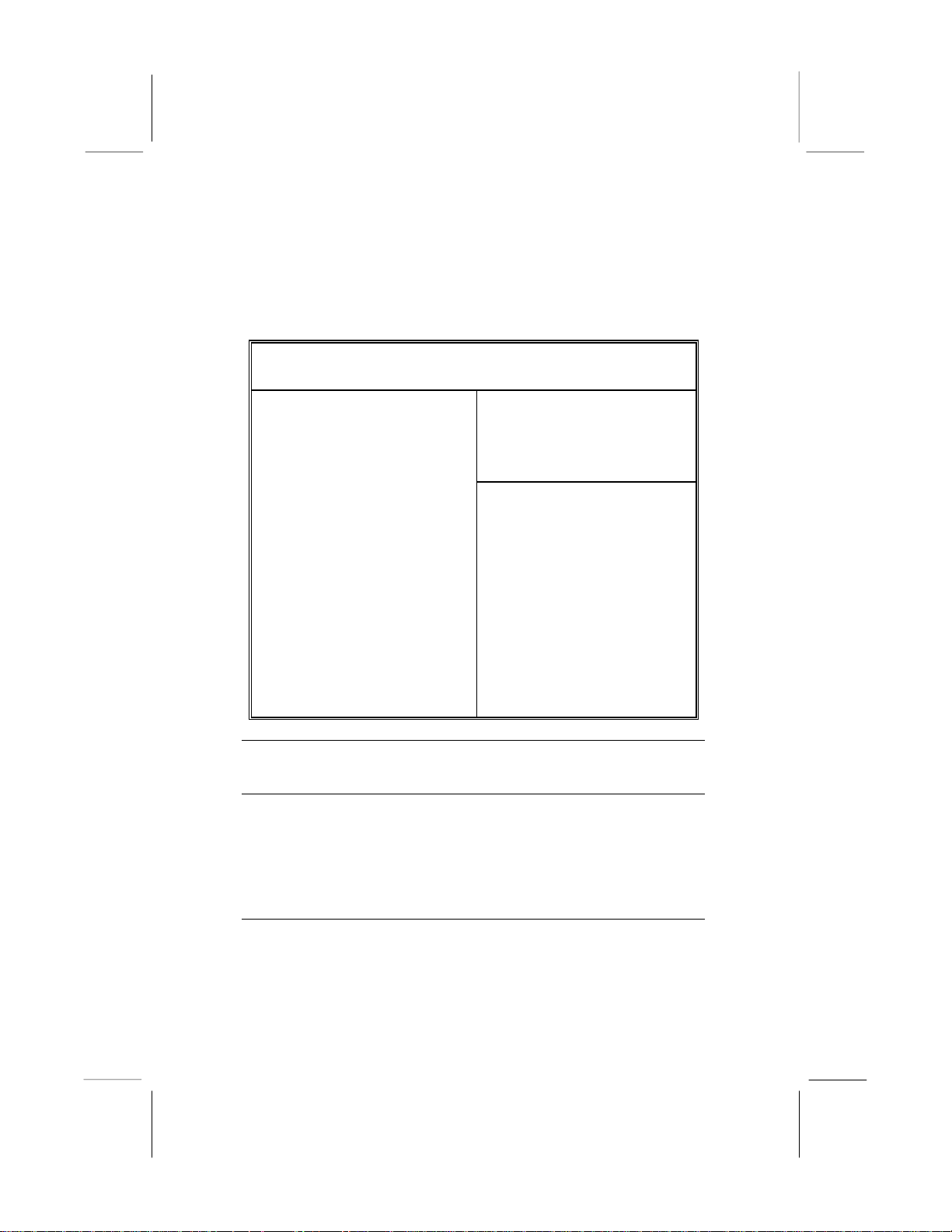
This page sets some of the parameters for the hardware monitoring
function of this mainboard.
AMIBIOS SETUP – HARDWARE MONITOR
(C) 2000 American Megatrends, Inc. All Rights Reserved
--- Hardware Monitor ---
SYSTEM Temperature
38°C/100°F Fan#1 Speed
5314 RPM
Fan#2 Speed 0
RPM
Vcore 1.616
V
+1.800V 2.496 V
Vcc3 3.296
V
Vcc 4.972 V
+12V
11.968 V
SB5V 5.053
V
ESC : Quit ↑↓←→ :
Select Item
F1 : Help
PU/PD/+/- : Modify
F5 : Old Values
(Shift)F2 : Color
F6 : Load Optimal values
F7 : Load Best performance
values
CPU
Temperature
FAN#1, 2
Speed &
Voltage
Measurement
s
These items display CPU and the system
temperature measurement. The system will alert
you if a safe temperature is exceeded.
These items indicate cooling fan speeds in RPM
and the various system voltage measurements. If
the values deviate beyond certain limits, the
hardware monitoring feature will alert you with a
warning.
Change Password
If you highlight this item and press Enter, a dialog box appears
which lets you enter a Supervisor password. You can enter no more
33
Page 41

Mainboard User’s Manual
than six letters or numbers. Press Enter after you have typed in the
password. A second dialog box asks you to retype the password for
confirmation. Press Enter after you have retyped it correctly. The
password is then required to access the Setup Utility or for that and
at start-up, depending on the setting of the Password Check item
in Advanced Setup.
Change or Remove the Password
Highlight this item, press Enter and type in the current password.
At the next dialog box, type in the new password, or just press
Enter to disable password protection.
Exit
Highlight this item and press Enter to save the changes that you
have made in the Setup Utility configuration and exit the program.
When the Save and Exit dialog box appears, press Y to save and
exit, or press N to exit without saving.
34
Page 42

4: Software & Applications
Chapter 4
Software & Applications
Introduction
This chapter describes the contents of the support CD-ROM that
comes with the mainboard package.
The support CD-ROM contains all useful software, necessary
drivers and utility programs to properly run our products. More
program information is available in a README file, located in the
same directory as the software.
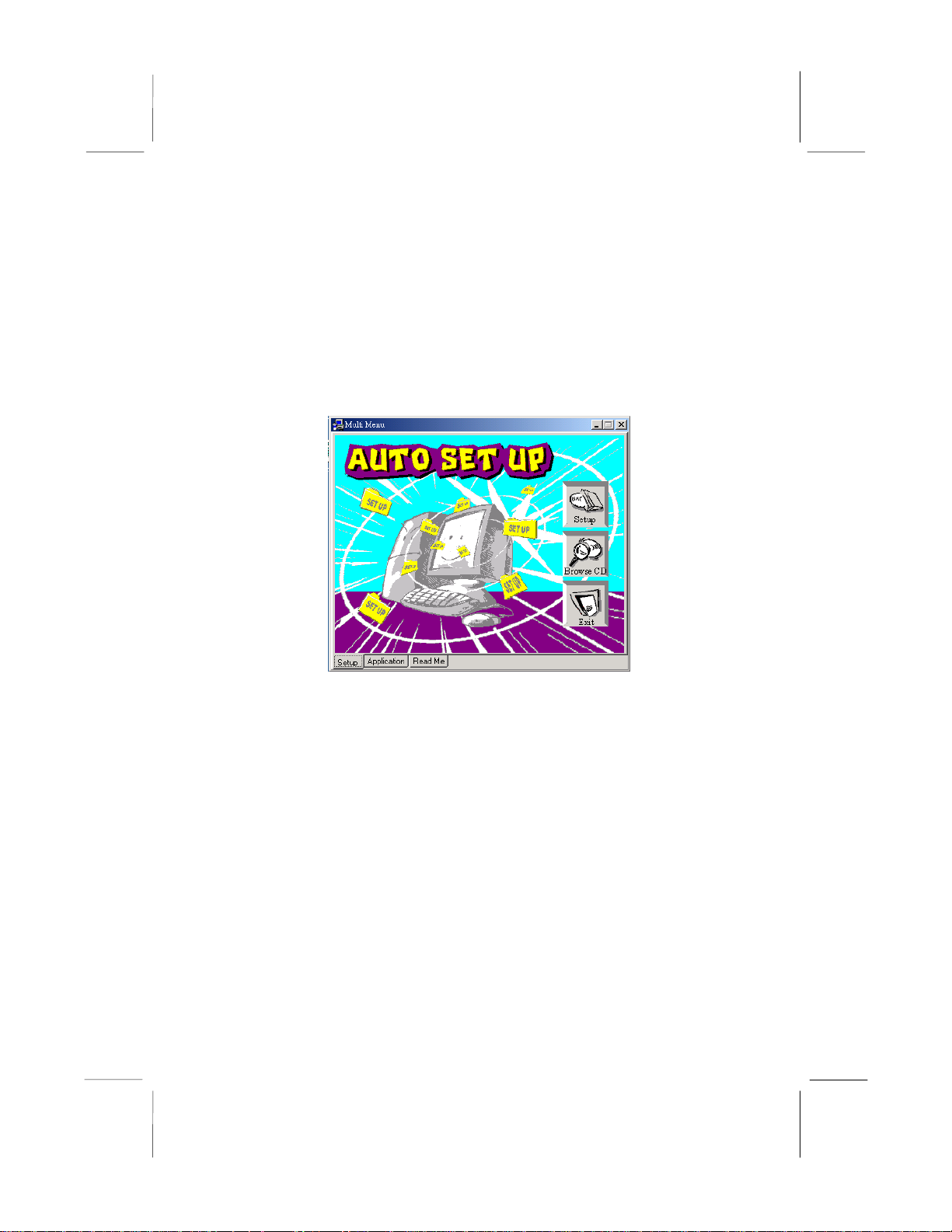
To run the support CD, simply insert the CD into your CD-ROM
drive. An Auto Setup screen automatically pops out, and then you
can go on the auto-installing or manual installation depending on
your operating system.
If your operating system is Windows 98/ME/2000/XP, it will
automatically install all the drivers and utilities for your
mainboard; if Windows NT or manual installation, please follow
the instructions described as the Installing under Windows NT or
Manual Installation section.
35
Page 43
Mainboard User’s Manual
Installing Support Software
1.Insert the support CD-ROM disc in the CD-ROM drive.
2.When you insert the CD-ROM disc in the system CD-ROM
drive, the CD automatically displays an Auto Setup screen.
3.The screen displays three buttons of Setup, Browse CD and Exit
on the right side, and three others Setup, Application and
ReadMe at the bottom. Please see the following illustration.
The Setup button runs the software auto-installing program as
explained in next section.
The Browse CD button is a standard Windows command that you
can check the contents of the disc with the Windows 98 file
browsing interface.
The Exit button closes the Auto Setup window. To run the
program again, reinsert the CD-ROM disc in the drive; or click the
CD-ROM driver from the Windows Explorer, and click the Setup
icon.
The Application button brings up a software menu. It shows the
bundled software that this mainboard supports.
The ReadMe brings you to the Install Path where you can find out
path names of software driver.
36
Page 44
4: Software & Applications
Auto-Installing under Windows 98/ME/2000/XP
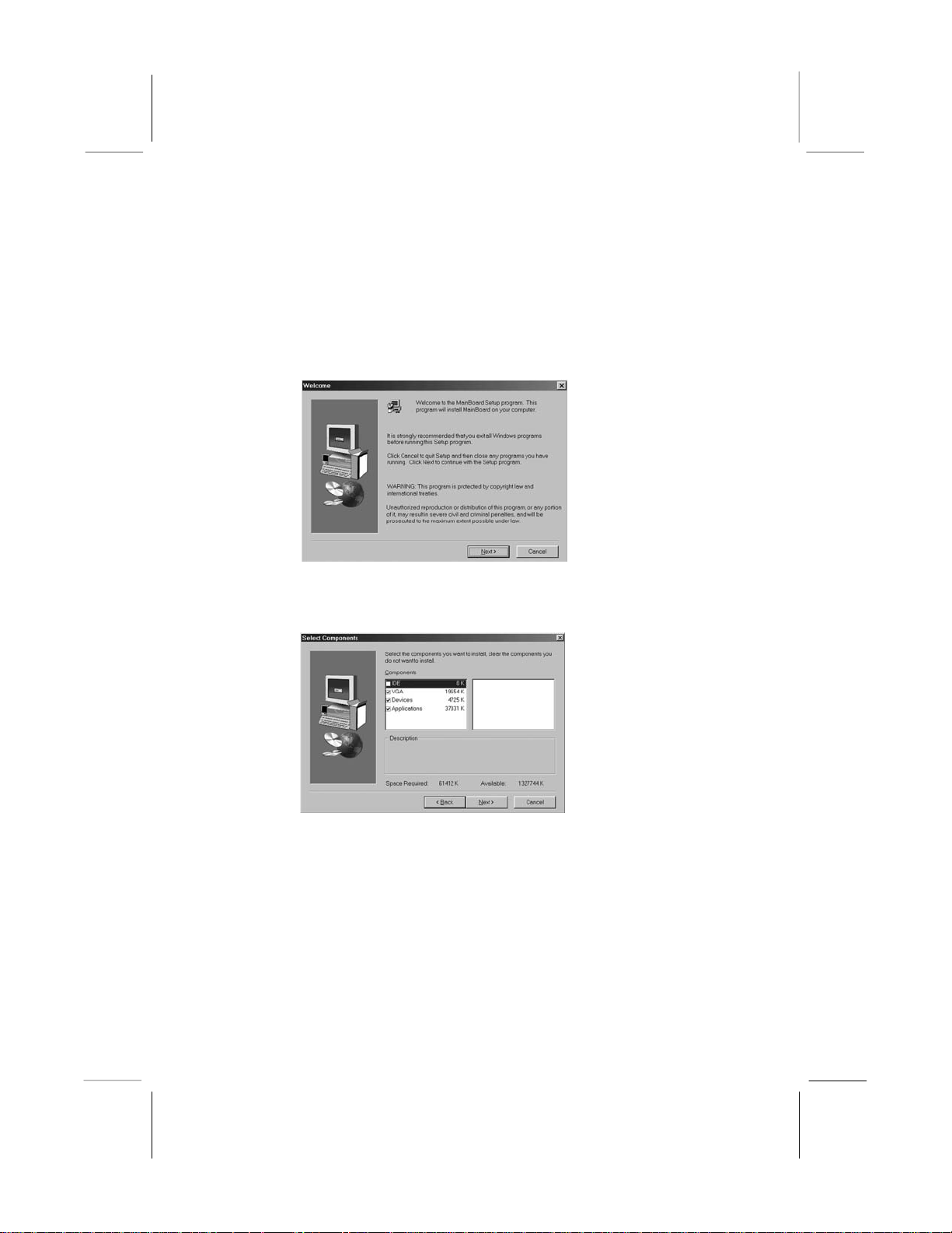
If you are under Windows 98/ME/2000/XP, please click the Setup
button to run the software auto-installing program while the Auto
Setup screen pops out after inserting the support CD-ROM:
1. The installation program loads and displays the following
screen. Click the Next button.
2. Select the items that you want to setup by clicking on it (the
default options are recommended). Click the Next button to
proceed.
3. The support software will automatically install.
Once any of the installation procedures start, software is
automatically installed in sequence. You need to follow the
onscreen instructions, confirm commands and allow the computer
to restart as few times as needed to complete installing whatever
software you selected. When the process is finished, all the support
software will be installed and start working.
37
Page 45

Mainboard User’s Manual
Installing under Windows NT or Manual Installation
If you are under Windows NT, the auto-installing program doesn’t
work out; or you this procedure while the Auto Setup screen pops
out after inserting have to do the manual installation, please follow
the support CD-ROM:
1. Click the ReadMe to bring up a screen, and then click the
Install Path at the bottom of the screen.
2. Find out your mainboard model name and click on it to obtain
its correct driver directory.
3. Install each software in accordance with the corresponding
driver path.
Bundled Software Information
All bundled software available on the CD-ROM is for users’
convenience. You can install bundled software as follows:
1. Click the Application button while the Auto Setup screen pops
out after inserting the support CD-ROM.
2. A software menu appears. Click the software you want to install.
3. Follow onscreen instructions to install the software program step
by step until finished.
38
Page 46

4: Software & Applications
Technical Support
Please follow the steps outlined below before calling in for
technical support:
1) If you have any problems, please clear the Bios first.
Instructions can be found on page 11 of this manual.
2) Set the System boot order under the Bios menu, under the
Advanced BIOS Features to resemble the list below:
First Boot Device- Floppy
Second Boot Device- CDROM
Third Boot Device- HDD-0
Linux Issues:
For any questions regarding ThizLinux Version 5.0 or any other
Linux related issues, please contact them directly at
www.thizlinux.com
or ThizLinux
We do not provide any support for Linux
Windows Installation Issues:
You will need the following:
o Window 98/ME CD full version
o Window 98/ME start up disk (You can make on by going
to any computer with Windows 98 -> start -> setting ->
control panel -> add/remove programs -> startup disk ->
create disk) **Also downloadable from our website
www.fryssupport.net
• Linux Erase Utility disk (you can create one by
downloading it from www.fryssupport.net
onto a floppy disk, and the same for the boot disk.
• a) Please set the boot order within your Bios to floppy,
CDROM, HDD-0.
and saving it
39
Page 47

Mainboard User’s Manual
• b) Place the Windows 98 startup disk into the floppy drive
and turn on (or restart) the computer
• c) A screen labeled "Microsoft Windows 98 Startup Menu"
will appear. Press the number <1> to start the computer
with CD-ROM support. (if you see "no valid FAT…"
message, don't panic, this is normal)
• d) At the A:\>, remove the Windows 98 startup disk and
insert the Linux Erase Utility disk.
• e) Type at the A: prompt "del-pat" without the quotation
marks. The program will now run for 3 to 5 mins. When
the red light in front of the computer goes off and the A:
prompt returns, the program is done.
• f) Now take out the Linux Erase Utility floppy and put in
the Window 98 CD
• g) Restart your computer
• h) Select "Boot from CD-ROM"
• i) Select <1> - "Start Window 98 Setup from CD-ROM.
• j) The next screen will ask you to press <enter> to install
Windows 98. Press <enter>
• k) The next screen will ask you to allocate space on your
hard drive. Using the <up arrow> and <down arrow> key,
select "Configure Unallocated Space". Once that selection
is highlighted, press <enter>.
• l) The next screen will ask you if you would like to enable
large disk support. Select "Yes, enable large disk support"
and hit <enter>
• m) Windows 98 will now restart. Leave the Windows 98
CD in the computer. (You do not need to insert the
Windows 98 boot disk)
40
Page 48

4: Software & Applications
• n) Select "Boot from CD" and continue with the Windows
98 installation process.
Power Problems:
Check the power light- Make sure that there the lights on the front
of your computer system is lit. If the lights are blinking, it
probably means that the computer is in standby mode. Press any
key on your keyboard or move your mouse to get out of standby
mode.
Make sure that your electrical outlet is working by plugging in a
working electrical appliance.
Make sure that the power cable is firmly inserted into the electrical
outlet and the computer power connector on the back of your
computer system.
Connecting a Printer:
Turn off the computer first.
Then, attach a standard parallel cable from the back of the printer
to the parallel port on the back of your computer, taking care to
tighten the two screws on the connection to the computer and
snapping the two clips into the two notches on the back of the
printer.
Turn on the printer and then turn on your computer
The Add New Hardware Wizard window should appear, and
follow all shown instructions.
Video/Monitor Problems:
Check to make sure that the monitor is powered on
Make sure that the cable connections are firm on both end.
Swap the computer/monitor power and connection cables to ensure
that there are no problems with the cables.
I can only see 2 or 16 colors on screen and my resolution can only
be adjusted to 640x480 or 600x800.
This means your onboard video card driver is not installed. To
install the driver, do the following:
a) Put the Software CD with all the drivers into the CDROM
drive
41
Page 49

Mainboard User’s Manual
b) Click on "Setup" and then check the box for VGA
c) If the computer asks for an "OS", insert your Windows CD,
wait for the CD to spin up, and then direct the computer to look for
the files in the "WIN98" folder or “I386” folder for Windows®
2000 & Windows® XP.
d) The computer will restart before the new settings take effect.
If this does not solve your video problem, please email us at our
website
If screen is difficult to read:
Adjust the contrast and brightness on the monitor
Make sure that the sub woofer is is at least 2 ft away from the
Turn off possible interference factors such as nearby fans,
Sound/Speaker Problems:
Ensure that the speakers are connected to their proper connections
Make sure that the speakers are turned on and that the volume is
Make sure that the volume is not muted from within the Windows
Make sure that the correct sound driver has been installed into the
Modem Problems:
Make sure that the telephone jack is working by disconnecting the
Verify that the modem is properly communicating with Windows
In the control panel, double click on the modems icon. If there are
www.fryssupport.net
monitor
fluorescent lights, or even halogen lamps
as shown in the quick setup guide.
adjusted to a proper setting.
operating system
system
line and connecting a regular telephone. You should hear a dial
tone.
by going to the Start Settings Control Panel
multiple entries for the same modem, or modems listed that are
not installed, remove/delete the entries and restart your system.
42
Page 50

4: Software & Applications
Go back to the same place in the control panel, click on the
diagnostic tab.
Click on the COM port of your modem
Click More Info to see that the modem is properly installed and
communicates with Windows. If all commands receive
responses, the modem is operating correctly.
43
 Loading...