


S/M No. :
Service Manual
Model : TVR950
July .2002
VIDEO CASSETTE RECORDER
4-HEAD RECORDER / Hi-Fi STEREO / REMOTE CONTROL

1
TABLE OF CONTENTS
SPECIFICATION ........................................................................................
WAVEFORMS ............................................................................................
CIRCUIT DIAGRAM ..................................................................................
POWER SUPPLY SCHEMATIC DIAGRAM ...........................................................
SERVO/SYSCON SCHEMATIC DIAGRAM ...........................................................
VIDEO/AUDIO SCHEMATIC DIAGRAM(4HEAD) ..................................................
VIDEO/AUDIO SCHEMATIC DIAGRAM(Hi-Fi) ......................................................
PIF SCHEMATIC DIAGRAM(4HEAD) ....................................................................
PIF & MPX SCHEMATIC DIAGRAM(Hi-Fi) ............................................................
PCB CIRCUIT BOARD ..............................................................................
INSTRUMENT DISASSEMBLY .................................................................
ELECTRICAL PARTS LIST ......................................................................
BS MODEL PART LIST ...........................................................................................
MODEL LIST & OPTION TABLE .............................................................................
*APPENDIX
TROUBLESHOOTING GUIDES ...............................................................
POWER CIRCUIT ....................................................................................................
SERVO/SYSCON/LOGIC CIRCUIT .........................................................................
VIDEO CIRCUIT .......................................................................................................
AUDIO CIRCUIT (Hi-Fi MODEL) .............................................................................
AUDIO CIRCUIT (4HEAD MODEL) .........................................................................
2
3
7
13
14
19
1
7
8
9
10
11
12
19
38
1
2
9
13
18
2
SPECIFICATION
Note: Specifications are subject to change without notice.
Power Input
120 Volts AC 60Hz
Power Consumption
17 Watts (4-head Hi-Fi)
Operating Temperature
5 degree C to 40 degree C (41 degree F to 104 degree F)
Storage Temperature -30 degree C to 65 degree C (-22 degree F to 149 degree F)
Weight
6.6 Ibs : Net (8.8 Ibs : Gross)
Dimensions
14.2 X 3.6 X9.4 Inches
Recording System
4-head Hi Fi: Four video record/playback heads Rotary helical scan
Luma: FM recording
Chroma: converted subcarrier phase shifted recording
Two audio record/playback heads
Rotary helical scan, 2 channels FM recording
Rotary helical scan
Video Signal EIA standard; NTSC color
Antenna 75 ohm input impedance
Video Signal Level 1Vp-p (140 IRE standard)
Audio Input Impedance More than 47K ohm
Audio Output Impedance Less than 1.5K ohm
Tape Speed
SP: 33.35mm/sec.
SLP: 11.13mm/sec
Maximum Recording Time
T-60: 3 hours/ EP (SLP) mode
T120: 6 hours/ EP (SLP) mode
Fast Forward/Rewind Time < 130 sec (T-120 tape)
Tuning System Auto Program/Cable Compatible/Frequency Synthesis (FS)
3
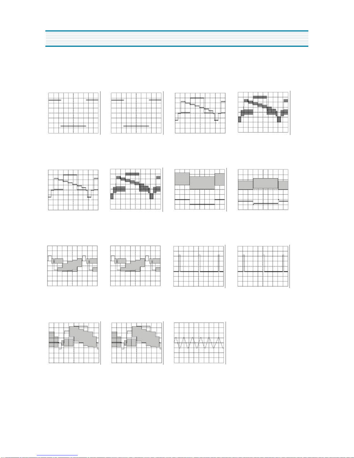
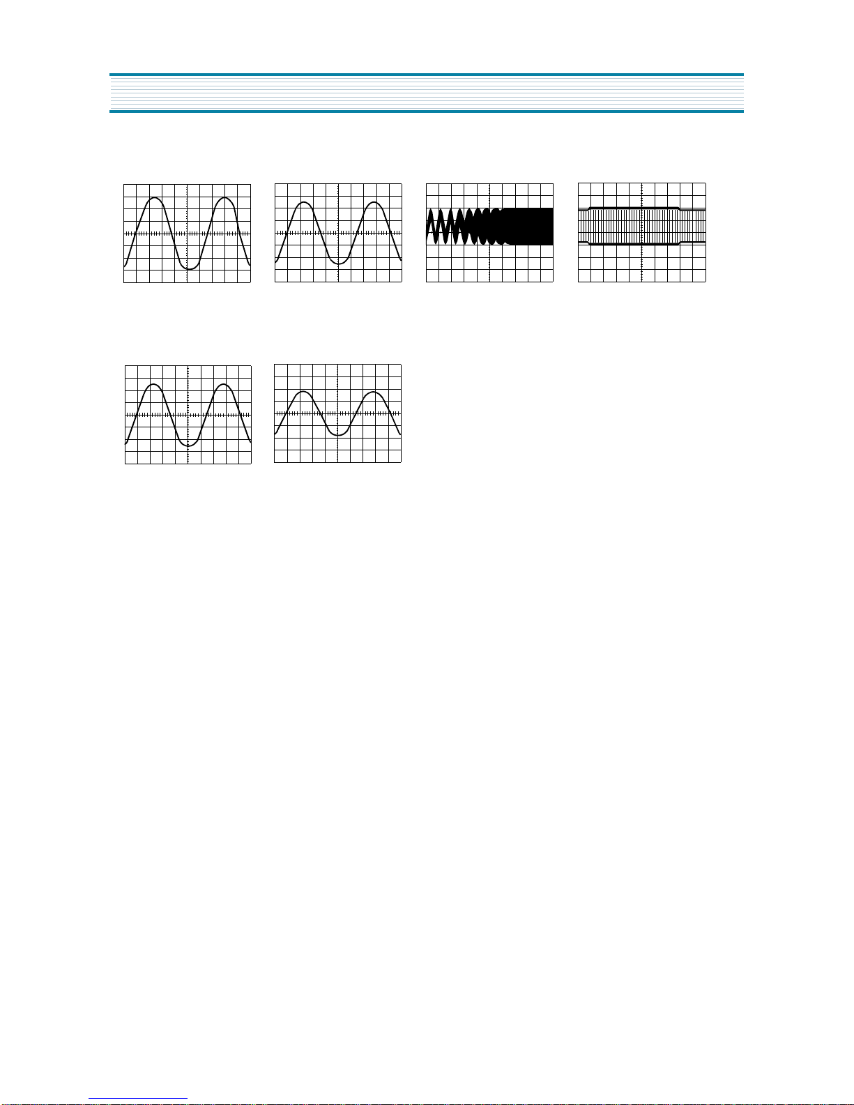
WAVEFORMS
1. LUMA / CHROMA WAVEFORMS
(IC301-57) 5Vp-p
1V/2msec/cm
REC
(IC301-57)5Vp-p
1V/2msec/cm
PLAY
(IC301-20) 520mVp-p
200mV/5usec/cm
REC
(IC301-20) 520mVp-p
200mV/5usec/cm
PLAY
(IC301-22) 520mVp-p
100mV/5usec
REC
(IC301-22) 520mVp-p
100mV/5usec
PLAY
(IC301-14) 650mVp-p
200mV/2msec/cm
PLAY(SP) VIDEO SW TRIG
(IC301-14) 450mVp-p
200mV/2msec/cm
PLAY(SLP) VIDEO SW TRIG
(IC301-36) 300mVp-p
100mV/5usec/cm
REC
(IC301-36)300mVp-p
100mV/5usec/cm
PLAY
(IC301-25) 4.6Vp-p
2V/10usec/cm
REC/PLAY
(IC301-25) 4.6Vp-p
2V/10usec/cm
PICTURE SEARCH
(IC301-26) 2.2Vp-p
500mV/5usec/cm
REC
(IC301-26) 2.2Vp-p
500mV/5usec/cm
PLAY
(IC301-49) 450mVp-p
200mV/0.1usec/cm
1. 1.
2. 2.
3.3.
5.
7. 7. 8.
5. 6. 6.
4. 4.
4
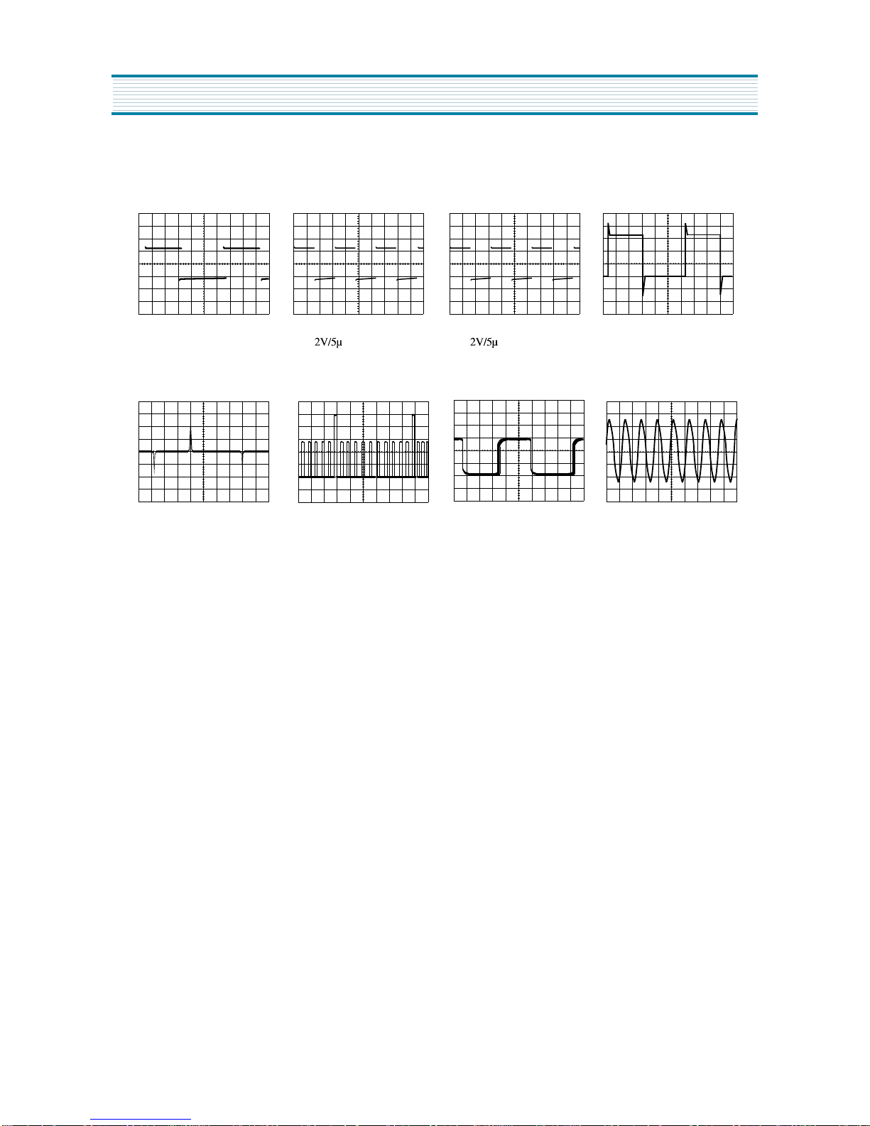
WAVEFORMS
2. SERVO WAVEFORMS
SER
VO WAVEFORMS
(IC601-38) 2.6Vp-p
0.5V/0.1 sec/cm
REC/PLAY
(IC601-18) 5Vp-p
2V/5msec/cm
REC/PLAY
(IC601-77) 5Vp-p
sec/cm
REC/PLAY
(IC601-76) 5Vp-p
sec/cm
REC/PLAY
(IC601-94) 3Vp-p
1V/5msec/cm
REC
(IC601-97) 4.4Vp-p
1V/5msec/cm
PLAY
(IC601-90) 25Vp-p&5Vp-p
1V/5msec/cm
REC/PLAY
(IC601-87) 2.5Vp-p
1V/0.2msec/cm
REC/PLAY
14.
18.
22.
20. 21.
15. 16. 17.
5
WAVEFORMS
3. AUDIO WAVEFORMS
AUDIO W
(IC301-76) 120mVp-p
20mV/0.5msec/cm
REC
(IC301-10) 1.5Vp-p
0.5V/0.5msec/cm
REC
(IC301-9) 2.5Vp-p
0.5V/0.5msec/cm
REC
(IC301-2) 120mVp-p
50mV/0.5msec/cm
PLAY
(Q203-C) 7.0Vp-p
10V/20 sec/cm
REC
9. 10.
13.
11. 12.
6
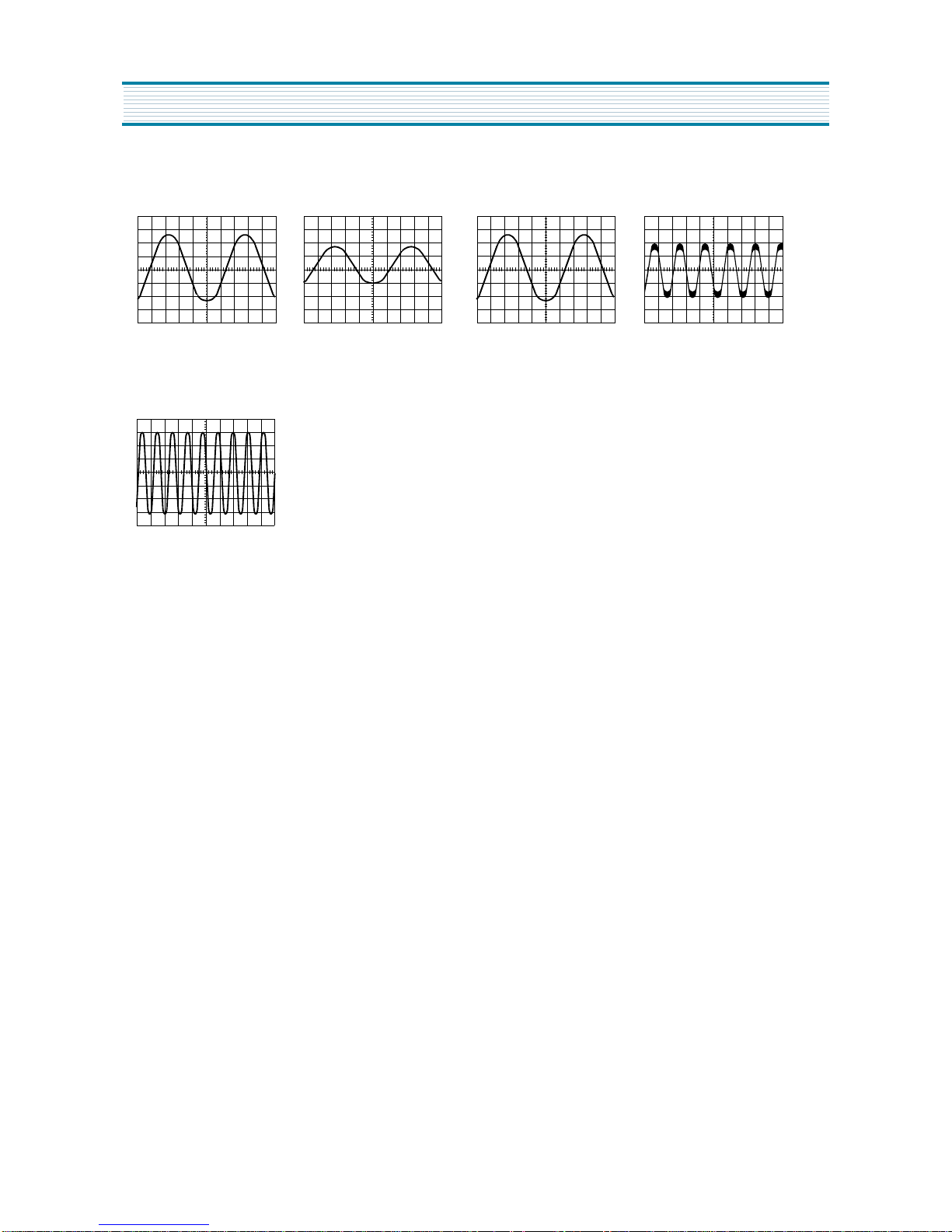
WAVEFORMS
4. Hi-Fi AUDIO WAVEFORMS
(IC251-9) 120mVp-p
20mV/0.5msec
EE/REC/PLAY
(IC251-19) 250mVp-p
50mV/0.5msec
EE/REC
(IC251-21) 1.4Vp-p
0.5V/1msec
REC
(IC251-29) 600mVp-p
0.2V/2msec
PLAY
(IC251-32) 250mVp-p
50mV/0.5msec
EE/REC
(IC251-57) 1.4Vp-p
0.5V/0.5msec
EE/REC
23.
27. 28.
24. 25. 26.
7
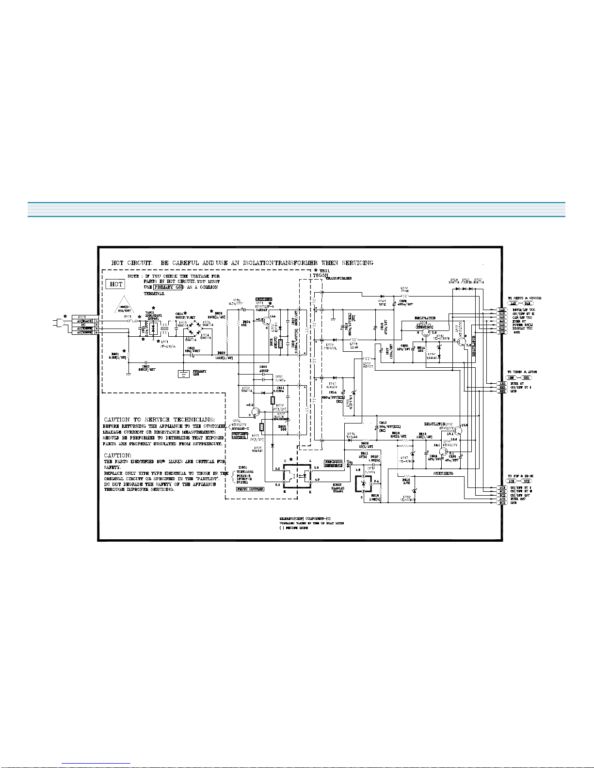
CIRCUIT DIAGRAM
1. POWER SUPPLY SCHEMATIC DIAGRAM
8
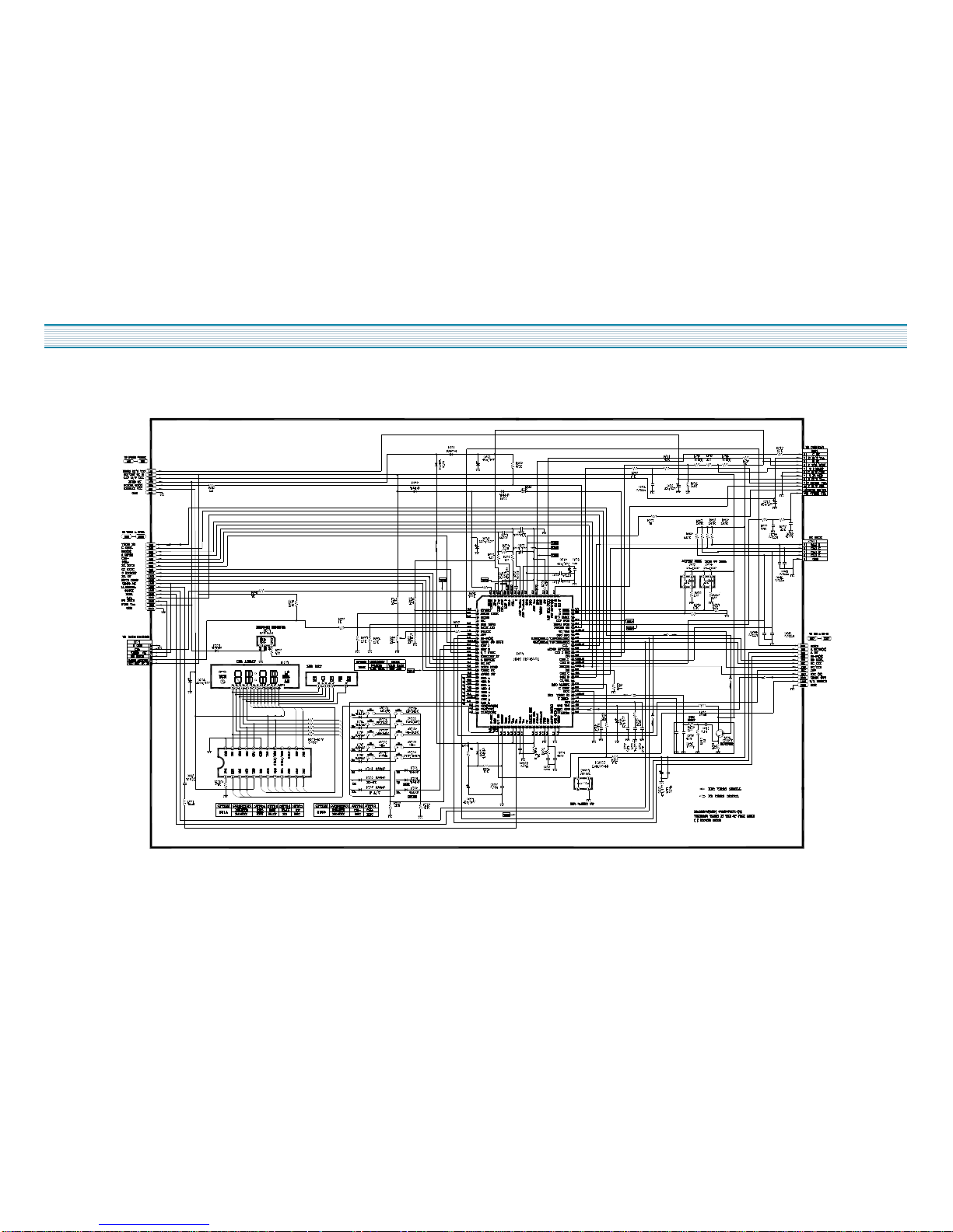
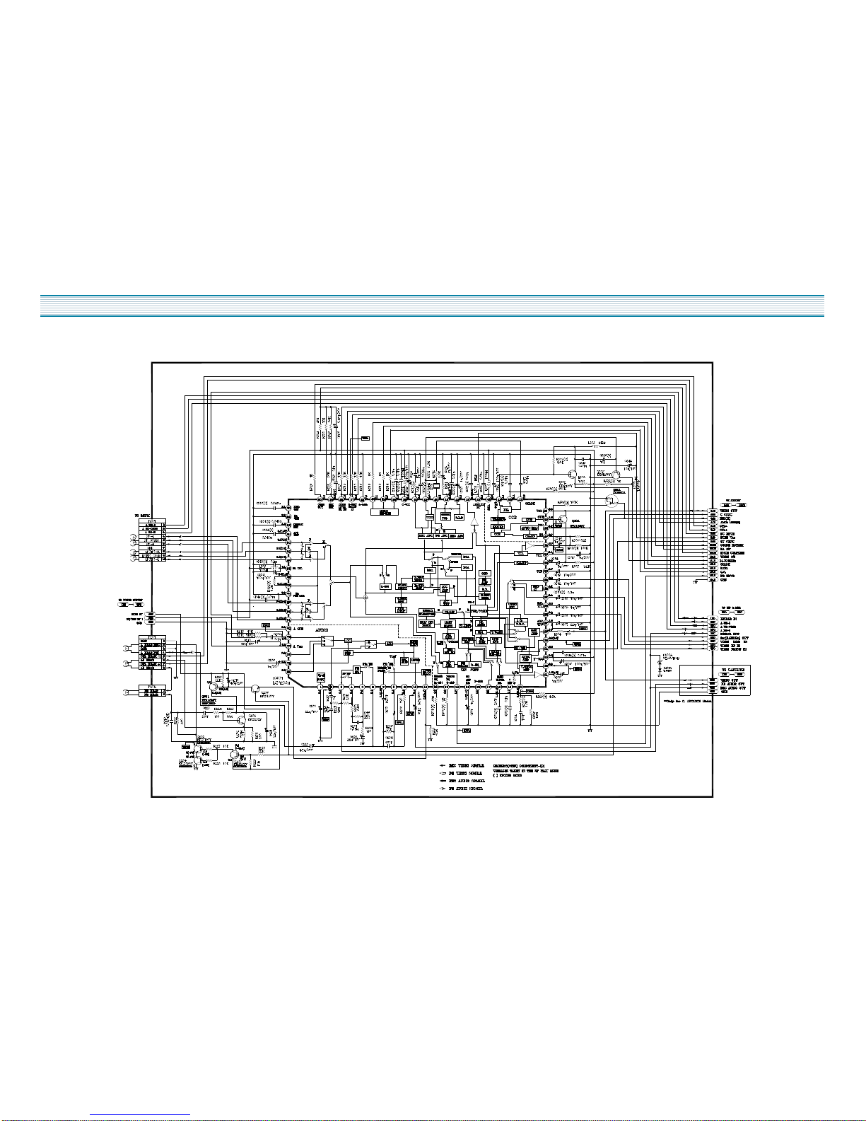
CIRCUIT DIAGRAM
2. SERVO/SYSCON SCHEMATIC DIAGRAM
9
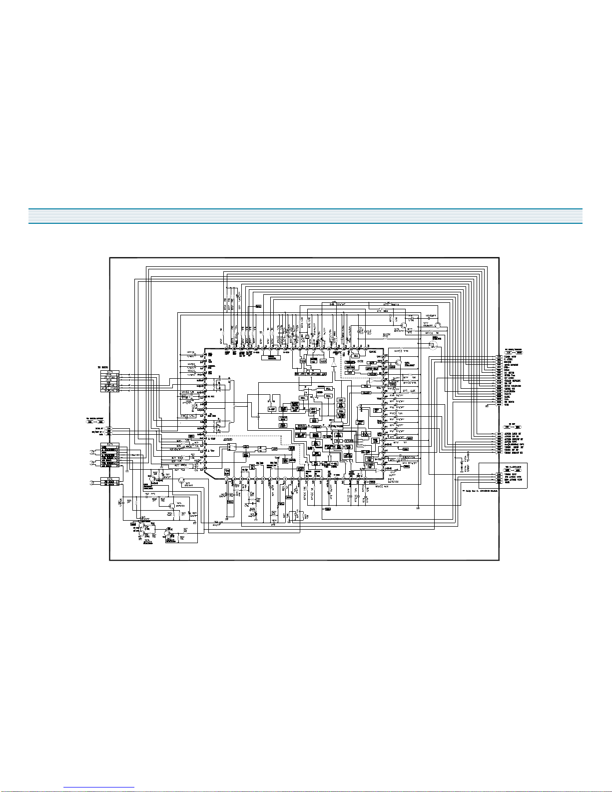
CIRCUIT DIAGRAM
3. VIDEO/AUDIO SCHEMATIC DIAGRAM( 4HEAD )
10
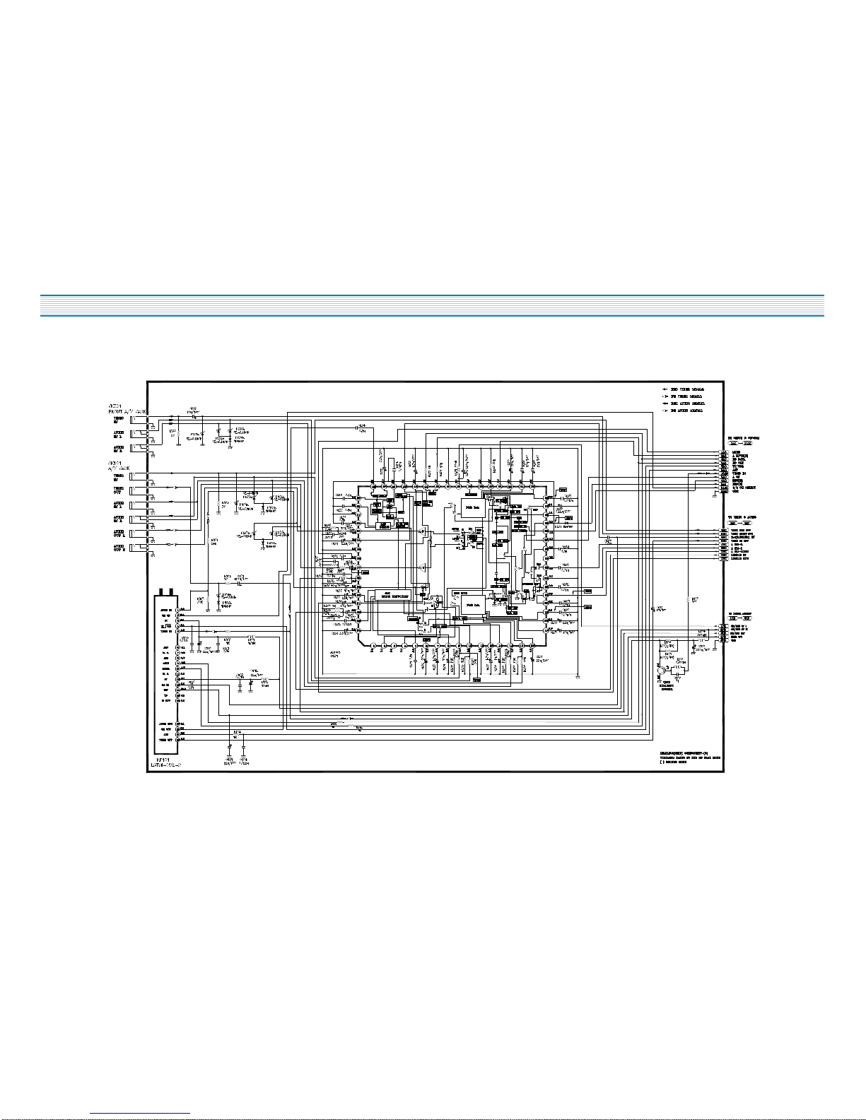
CIRCUIT DIAGRAM
4. VIDEO / AUDIO SCHEMATIC DIAGRAM (HI FI)

11
CIRCUIT DIAGRAM
5. PIF SCHEMATIC DIAGRAM( 4HEAD )
12
CIRCUIT DIAGRAM
6. PIF & MPX SCHEMATIC DIAGRAM ( HI - FI)
13
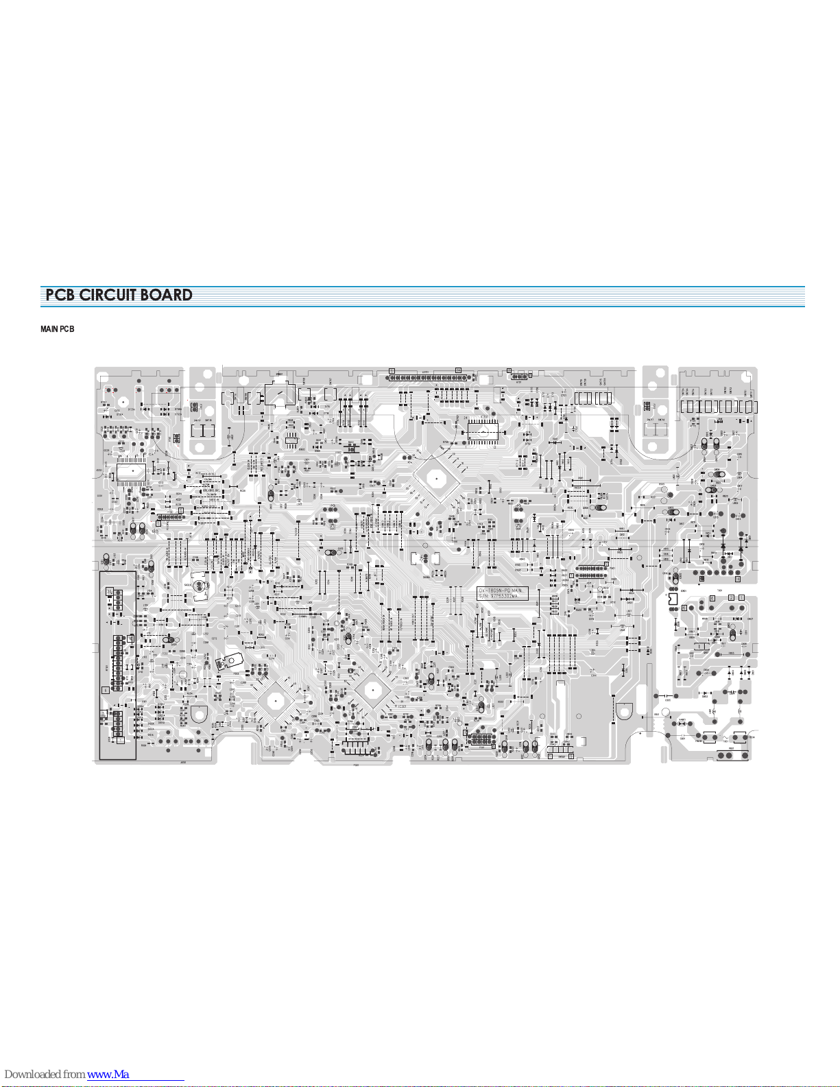
PCB CIRCUIT BOARD
MAIN PCB
14
INSTRUMENT DISASSEMBLY
Perform all disassembly procedures in the order presented. When reassembling,
use the reverse procedure. Make sure that all leads/wiring are routed correctly when reassembling.
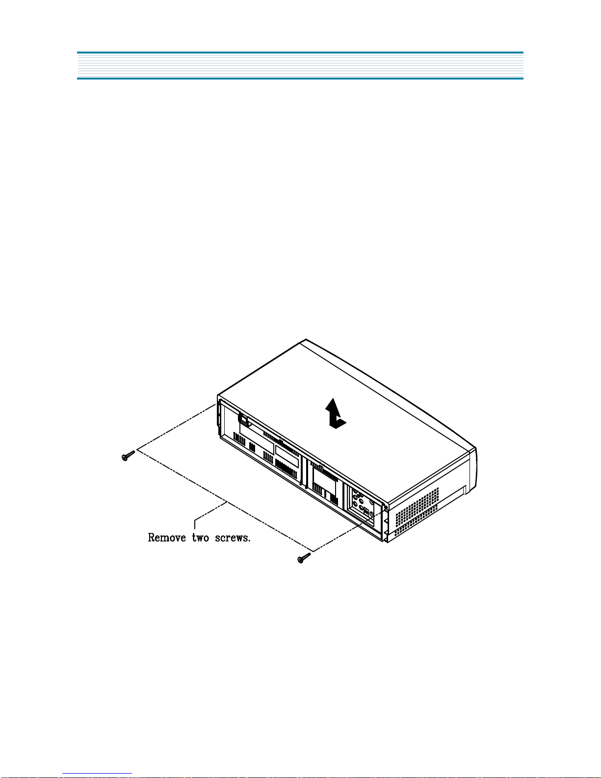
1. Top Cover Removal (Fig. 1)
1) Remove two(2) screws Holding the top cover.
2) Carefully lift the back of top cover and slide it to the rear to remove it.
15
INSTRUMENT DISASSEMBLY
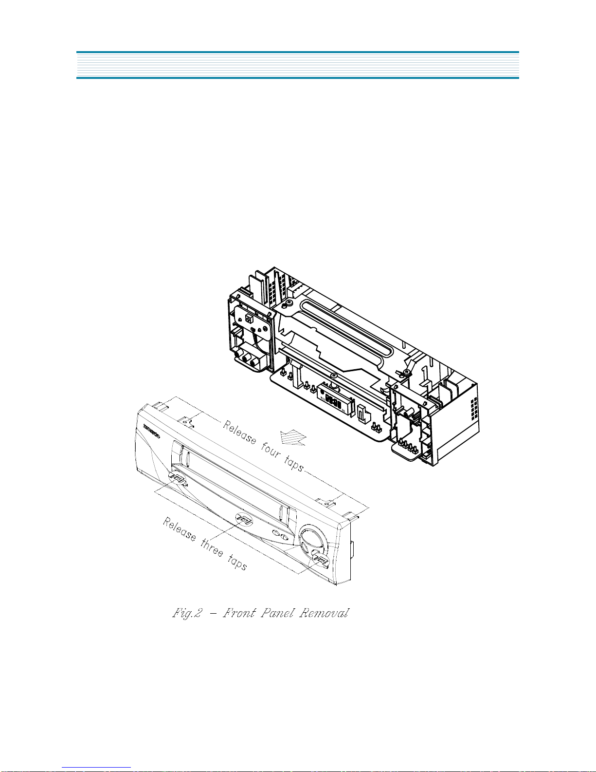
2. Front Panel Removal (Fig. 2)
1) Continued from (Fig. 1).
2) Release seven(7) tabs holding the front panel. (Release bottom tabs first)
3) Remove the front panel.
16
INSTRUMENT DISASSEMBLY
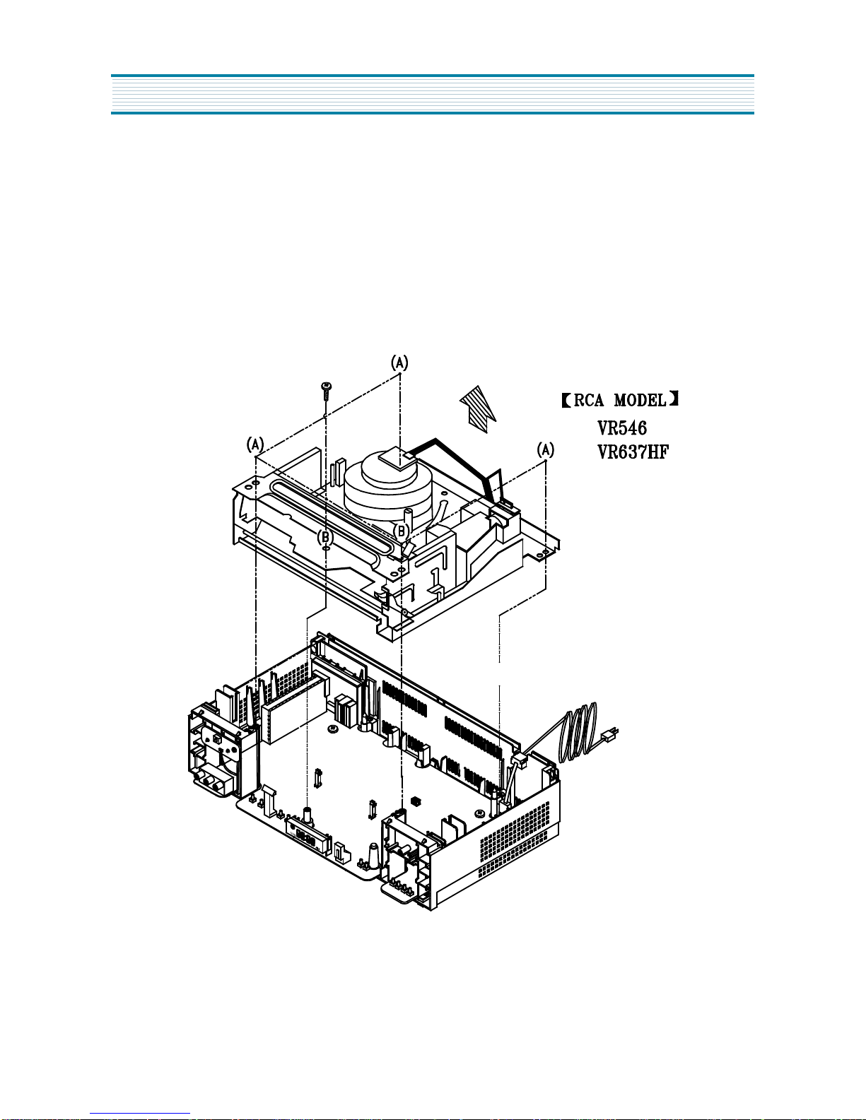
3. Deck Assembly Removal (Fig. 3)
1) Remove the top cover, the front panel
2) Disconnect the FPC
3) Remove five(5) screws (A) (B) (C) (D) (E).
4) Remove one(1) screw (F).
5) Pull out the Deck Assembly in the direction of the arrow.
17
INSTRUMENT DISASSEMBLY
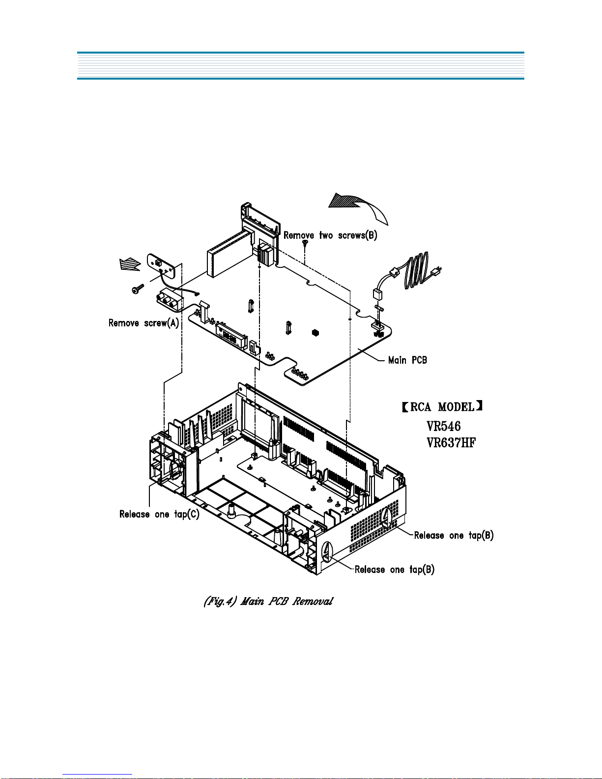
4. Main PCB Assembly Removal (Fig. 4)
1) Remove the top cover, the front panel, the bottom cover and the deck assembly.
2) Remove two(2) screws.
3) Release three(3) tabs (A) and lift out the Main PCB in the direction of the arrow.
 Loading...