

GP Systems BioSmart PV-WTC-EM, BioSmart PV-WTC-MF, BioSmart PV-WTC-HD, BioSmart PV-WTC-LG Installation Manual
1
BioSmart PV-WTC
Terminal
Installation guide

2

3
TABLE OF CONTENTS
GENERAL PRODUCT INFORMATION ..................................................................4
1. SPECIFICATIONS .................................................................................................5
1.1 BioSmart PV-WTC models .........................................................................5
1.2 Basic specifications ...................................................................................5
1.3 Factory settings .........................................................................................6
1.4 Package contents .......................................................................................6
2. USE, TRANSPORTATION AND STORAGE CONDITIONS .......................................6
3. SAFETY REQUIREMENTS ....................................................................................6
4. DISPOSAL ............................................................................................................7
5. MANUFACTURER’S GUARANTEE ........................................................................7
6. INSPECTION CERTIFICATE ..................................................................................7
7. TERMINAL DESCRIPTION ....................................................................................8
7.1 Description of terminal’s front panel ..........................................................8
7.2 Description of connection ports ................................................................10
7.3 Description of indicators and circuit board jumpers..................................11
8. INSTALLATION .....................................................................................................11
8.1 Installation notes ........................................................................................11
8.2 Installation procedure ................................................................................12
8.3 Connecting the terminal’s power supply ....................................................14
8.4 Connecting the terminal to an Ethernet network .......................................15
8.5 Connecting an electromechanical lock to the terminal’s circuit board......17
8.6 Connecting an electromagnetic lock through the BioSmart BCR ..............18
8.7 Connecting an entry sensor and control buttons ......................................19
8.8 Connecting to an external controller through Wiegand .............................20
9. CONFIGURING NETWORK PARAMETERS ............................................................21
10. ENSURING OF THE OPERATION ..........................................................................22
4
Dear customers!
Thank you for purchasing our product. With proper installation and use, this device will
bring you many years of reliable service.
GENERAL PRODUCT INFORMATION
The BioSmart PV-WTC work and attendance terminal is designed for use as part of the
BioSmart biometric access monitoring and control system. The terminal provides a means
to track working hours and attendance by identifying users through the unique biometric
characteristics of subcutaneous palm veins and RFID proximity cards. It can also be used
for access monitoring and control.
Compatible with BioSmart-Studio software version V5.0.3.269 and above.
Four models of this terminal are available:
- With Em-Marin (EM) card format scanner;
- With Mifare (MF) card format scanner;
- With HID iClass and HID Prox (HD) card format scanner;
- With Legic (LG) card format scanner.

5
1. SPECIFICATIONS
1.1 BioSmart PV-WTC models
Designation Device serial number
BioSmart PV-WTC-EM
BioSmart PV-WTC-MF
BioSmart PV-WTC-HD
BioSmart PV-WTC-LG
1.2 Basic specifications
Palm vein scanner type Optical, infrared
Maximum number of users* 1,000,000
Maximum number of card codes 1,000,000
Maximum number of palms
300,000
Maximum number of events
10,000,000
1:1000 vein matching identification time, sec
not longer than 2
False acceptance rate, % **
0.00008
Integrated RFID card scanner
Yes
Card scanning range, mm
up to 100
Display
TFT 3.5” 320х240
Keyboard
keypad, 12 buttons
BioSmart relay module support
Yes
Connection interface with computer
Ethernet
USB interface for configuration
USB 2.0
Web interface for configuration
Yes
Wiegand 26-40 bit output interface
Yes
On-board relay
12 VDC, 1 А
Number of discrete inputs, pcs
1
Power supply specifications
12 VDC±15%, 1 A
Outer dimensions (L x W x H), mm
215х150х117
Net weight, g
820
Gross weight, g
1270
Operating temperature range, °С
from 0 to plus 50
Operating relative air humidity, %
not higher than 90
Design
Detachable plastic body

6
1.3 Factory settings
Terminal’s IP address 175.25.110.71
Terminal’s network address Serial number
Administrator password
No password
1.4 Package contents
Item Number, pcs.
BioSmart PV-WTC Terminal 1
Product certificate 1
Installation instructions 1
Mounting kit (two 6х35 dowels, two
3.5х38 self-tapping screws)
1
2. USE, TRANSPORTATION AND STORAGE
CONDITIONS
Abrasive or chemically active materials should not be used to clean the outer surfaces of the device
or the palm vein scanner.
The terminal may be stored in the following environmental conditions:
- ambient air temperature from minus 40 to plus 50 °С;
- relative air humidity (without condensation) up to 98%.
Water, dust and other foreign substances should be prevented from entering the inside of the
terminal during transportation and storage. Following storage of the terminal in low temperature or
high humidity conditions, it must be kept in a dry environment at a temperature of (20±5) °С for no
less than 30 minutes before being turned on.
3. SAFETY REQUIREMENTS
To avoid malfunctions in the terminal, it must be disconnected from its power source before any
work is carried out with its case open.
Only specialists authorized by the manufacturers of this terminal should carry out the repair and
replacement of terminal parts.

7
4. DISPOSAL
The BioSmart PV-WTC terminal does not contain materials hazardous to the health of users or the
environment. No special ecological safety measures are required when disposing of this unit at the
end of its operational lifespan.
5. MANUFACTURER’S GUARANTEE
The manufacturer guarantees successful performance and correspondence to the stated product
characteristics on the condition that the consumer complies with the rules of its use, installation,
connection, transportation and storage.
The manufacturer provides a warranty on the BioSmart PV-WTC terminal for the period of 60
months from the day of sale indicated in its certificate.
If notes on the date of the product’s sale are absent from the certificate, the warranty period is
calculated from its manufacturing date.
The Manufacturer’s Warranty does not extend to BioSmart PV-WTC terminals that have broken
down due to the Customer failing to comply with its rules of operation.
6. INSPECTION CERTIFICATE
BioSmart PV-WTC- terminal, assembly no.
has been classified as fit for use.
Issue date
P r o d u c t i o n M a n a g e r
(signature)
(print full name)
Manufacturer:
GP Systems GmbH
Ochshäuser Str. 45
34123 Kassel Germany
e-mail: info@gp-systems.com
Tel. +49 151 100 41 701
8
7. TERMINAL DESCRIPTION
7.1 Description of terminal’s front panel
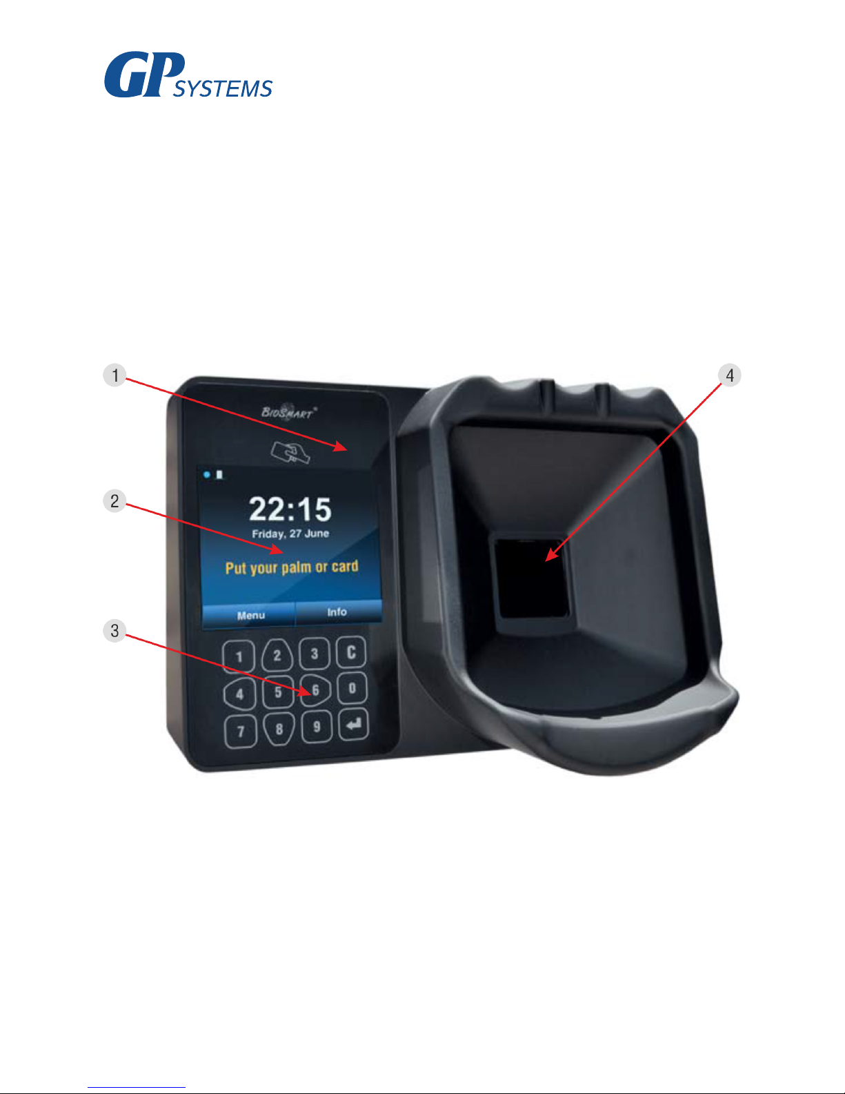
An exterior view of the terminal is shown on figure 1.
Figure 1. Exterior view of BioSmart PV-WTC terminal
1. Smart card reader
2. LCD screen
3. Keypad
4. Palm vein scanner

9
The terminal’s status panel is displayed at the top of the screen with the following symbols:
The instrument’s factory serial number is displayed in the top right corner of the status panel.
The screen displays the current date, time and day of the week.
The screen also features two buttons: “Menu” and “Info”. The “Info” menu displays all the information you need about the device’s state. The “Menu” button opens the device’s options.
The keypad buttons (fig. 2) are used to navigate through the on-screen menu:
2 – moves up the list;
6 – moves to the right or switches from list to
function buttons. Used for page navigation in
the “Users” menu;
4 – moves to the left or switches from func-
tion buttons to list. Used for page navigation in
the “Users” menu;
8 – moves down the list.
– used for selection and confirmation
С – used to return to the previous menu sec-
tion or delete the last digit entered.
Figure 2. Keypad
Operating mode indication
blue flashing symbol – terminal is ready to identify users
yellow flashing symbol – terminal is undergoing administration, identification is temporarily disabled
Output relay status Status of connection to BioSmart-Studio server
closed connection established
open no connection
Other indicators
connection with identification server established
free access mode enabled
terminal locked
there is an error in the terminal’s operation (error status indicated in the terminal’s “Info” menu)
The keypad is also used to enter all numeric settings.

10
7.2 Description of connection ports
A view of the terminal’s circuit board is shown in fig. 3. The circuit board’s contacts are described
in table 1.
Figure 3. Exterior view of terminal’s circuit board
1 2 3 4 5 6 7 8 9
11 12
10
Table 1. Circuit board connectors
No.
Label Description Connection purpose
1
REL 1st relay normally-open contact output (DC 1A, 12V) Actuator control input
2
REL 2nd relay normally-open contact output (DC 1A, 12V) Actuator power supply output
3
WG1 Wiegand interface DATA1 output
Wiegand external controller interface
DATA 1 intput
4
WG0 Wiegand interface DATA0 output
Wiegand external controller interface
DATA0 intput
5
IN+ +12V output for discrete input Relay control button
6
IN Discrete input Door sensor output, relay control button
7
485- - interface of RS485 connection with BCR -485 BCR contact
8
485+ + interface of RS485 connection with BCR +485 BCR contact
9
X3
Mini USB connector for terminal configuration using
the BioSmart Manager program.
Computer USB port
10
X4 RJ45(8P8C) port for Ethernet network connector Ethernet network interface
11
GND Power, ground Ground of 12V power supply
12
+12 V Power, +12V +12V power supply

11
7.3 Description of indicators and circuit board jumpers
The LEDs located on the Ethernet port indicate the physical connection’s state (Link, green) and
transfer activity (Activity, red).
The IPRST jumper is used to reset the network configuration to factory settings. To do this, you
must close the jumper contacts and wait for the Link and Activity LEDs to go out. Afterwards, the
jumper must be opened again.
The BOOT jumper is used to put the terminal into bootloader mode. This mode allows you to
restore the terminal to normal function if its firmware becomes corrupted. To enable bootloader
mode, you must close the BOOT jumper with the power off and then power on the terminal. After
the terminal is powered on, the contacts must be opened. The terminal’s display should show the
message “BOOT”. The process of loading the terminal’s firmware is described in more detail in the
terminal’s Operating Manual.
8. INSTALLATION
8.1 Installation notes
When deciding where to install the terminal, the following should be taken into account:
- The recommended height for the terminal is 120-150 cm from the floor, for reasons of convenience in positioning the palm on the scanner, presenting a card and viewing events on the LCD screen.
Access to the terminal should be free and unobstructed to allow for convenient positioning of the
palm.
- If installing multiple terminals, they must be placed no closer than 80 cm away from each other in
order to minimize mutual interference from their in-built RFID card readers.
- Installing a terminal within 1 m of any external RFID readers or other sources of electromagnetic
interference is not recommended. Nearby sources of electromagnetic interference may negatively
affect the operation of the built-in RFID card reader.
- It is recommended to leave some length in the cables attached to the terminal, enough to remove
the terminal from the wall and access its jumpers.
- If the device is installed on a metal surface, the range of its RFID card reader may be reduced.
When installing cables, please observe the following recommendations:
- Cables must be installed in accordance with the operational code for electrical installations;
- Do not lay cables within 30 cm of sources of electromagnetic interference;
- All cables must only intersect power cables at a right angle;
- Any cable extensions must be soldered.

12
Before installation:
- Carefully check for mechanical damage on the surface of the terminal’s palm scanner, circuit
board and housing;
- In order to avoid short circuits, the protected ends of cables used to connect the terminal must
not exceed 5 mm.
Cab. no.
Cable connection Max. length Type
1 Ethernet (IEEE 802.3) – terminal 100 m
Four twisted pair cables of no lower than
category five with a wire size of no less
than 0.2 mm
2
2 Power source – terminal power 2 m
Duplex cable with a wire size of no
less than 0.75 mm2 (for example, 3192Y)
3 Terminal – lock, BCR - lock 2 m
Duplex cable with a wire size of no
less than 0.75 mm2 (for example, 3192Y)
4
Terminal – BioSmart BCR
2 m
Four twisted pair cables of no lower than
category five with a wire size of no less
than 0.2 mm
2
5 IN, IN+ terminal contacts – external devices 2 m CQR-6 or RAMCRO-6 cable
6
WO0, WO1 terminal contacts – external
devices
2 m
Four twisted pair cables of no lower than
category five with a wire size of no less
than 0.2 mm
2
Table 2. Types of cables used:
8.2 Installation procedure
The terminal must be installed using the following procedure:
1. Open the box and verify that all the terminal’s parts are present.
2. Decide where you will install the terminal.
3. Unscrew the screws located in the lower part of the terminal housing which secure the housing
to the rear panel. Remove the rear panel.
4. Place the rear panel of the terminal on the wall and mark out the fixture points for the terminal
(fig. 4).
5. Lay and feed through all the required cables. The cables used must correspond to table 2, or
have similar technical characteristics. Ensure that there are no tears, breaks or mechanical defects in
the cables. Ensure that the power is off before connecting any cables.
6. Feed the cables through the hole for cable insertion in the terminal’s rear panel.

13
7. Fix the terminal’s rear panel onto the installation surface using the fixings included in the pack-
aging.
8. Connect the terminal’s power according to p. 4.3
9. Connect the terminal’s network cable according to p. 4.4
10. If necessary, connect the lock and external sensors according to p. 4.5 – 4.8 if using the termi-
nal for access monitoring and control or with external equipment through the Wiegand interface.
11. After connecting all the necessary cables, attach the terminal to the rear panel and screw in the
fastening screws located on the base.
Figure 4. Marking attachment points
Hole for cable
insertion
14
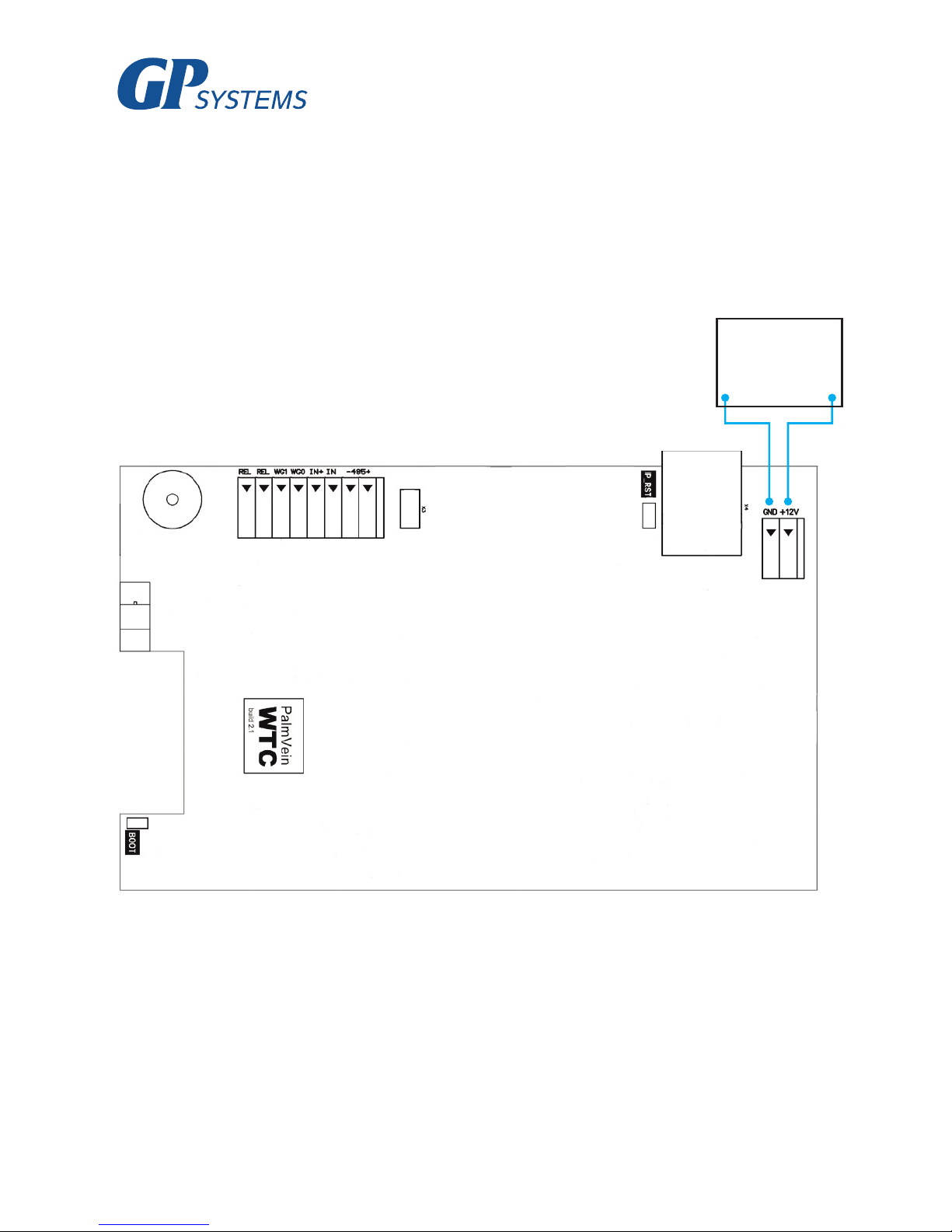
8.3 Connecting the terminal’s power supply
Use cable 2 (see table 2) to connect the power supply according to the connection diagram in
figure 6.
DC 12V
power
supply
GND +12V
Figure 6. Connecting the terminal’s power supply

15
8.4 Connecting the terminal to an Ethernet network
Connect the terminal to an Ethernet network according to figure 7.
Figure 7. Connecting to an Ethernet network
Network
interface

16
Use cable 1 (see table 2) to connect the terminal (via the Ethernet port) to a computer, network
switch or router. The order of connections in the cable’s modular connector must correspond to the
TIA/EIA-568-B standard, in accordance with figure 8.

17
8.5 Connecting an electromechanical lock to the terminal’s circuit
board
Figure 9 describes how to connect an electromechanical lock to the terminal. Use cable 3 (see table
2) to connect the electromechanical lock.
Figure 9. Connecting an electromechanical lock
Lock
Power
supply
+
-
18
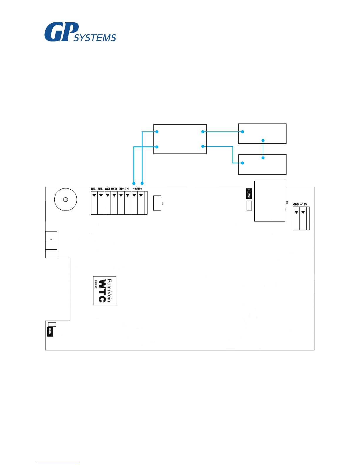
8.6 Connecting an electromagnetic lock through the BioSmart BCR
An electromagnetic lock is connected in conjunction with the BioSmart BCR in accordance with
figure 10.
Use cables 3 and 4 to connect it (see table 2).
Figure 10. Connecting an electromagnetic lock
The connection and configuration of the BioSmart BCR is described in detail in the BioSmart BCR
Operating Manual.
+485 NC1
BCR
-485 C1
Lock
PSU

19
8.7 Connecting an entry sensor and control buttons
An entry sensor or a control button for exiting the premises can be connected directly to the BioS-
mart PV-WTC terminal’s on-board discrete input.
Figure 11. Connecting a door sensor or button
to the on-board discrete input
Use cable 5 for this connection (see table 2).
If your access monitoring and control system requires the simultaneous use of an entry sensor and
button for exiting the premises, you must connect them using the BioSmart BCR.
Door sensor
or button

20
Figure 12. Connecting a door sensor and button
using the BioSmart BCR
Use cables 4 and 5 for this connection (see table 2).
The connection and configuration of the BioSmart BCR is described in detail in the BioSmart BCR
Operating Manual.
8.8 Connecting to an external controller through Wiegand
Figure 13 describes how to connect the terminal to an external AMCS controller through the Wie-
gand interface.
Use cable 6 for this connection (see table 2).
+485
BCR
-485

21
Figure 13. Connecting the terminal to an external
controller through the Wiegand interface
D0 (IN)
D1 (IN)
GND
9. CONFIGURING NETWORK PARAMETERS
Connect the terminal’s power supply. Wait for the screen to turn on.
Navigate through the on-screen menu using the corresponding keypad buttons (p. 3.1).
Press “Menu”. A prompt will appear on the display requesting the terminal’s configuration pass-
word. To log in, press .
The factory default password is an empty password.

22
When you log in to configuration mode for the first time, it is recommended that you set a new
password to avoid future unsanctioned access to the terminal’s options.
Go to the “Options” section, choose “Reset options” and press .
Warning! The “Reset options” button in this menu resets all the terminal’s settings to factory
default settings, and removes all user and event data saved in the terminal’s memory.
To change the terminal’s network settings, go to the “Network” section.
Choose the “New IP address” option from the list and press .
Enter the required IP address using the keypad and press .
Enter the required network mask and gateway options in the same way.
Navigate to the “Apply” button and press .
After this, the new network settings will go into effect.
The device is ready for use. Further configuration of the device should be carried out using the
BioSmart-Studio or BioSmart Manager programs.
The BioSmart PV-WTC Operating Manual and all necessary drivers and software can be found at
the address www.gp-systems.com in the “Technical Support” section.
10. ENSURING OF THE OPERATION
Go to the “Info” menu and confirm that the physical Ethernet network connection is established
and that there are no errors in the device’s operation.
If the device is connected correctly and its network options are configured correctly, the following
parameters should be displayed:
Next, a hardware test must be performed on the terminal.
To do this, press the “Menu” button. A prompt will appear on the display requesting the terminal’s
configuration password. To log in, press .
Select “Self-diagnostics” and press . Wait for the device’s diagnostic test results to appear on
the screen.
If there are no operational errors in the terminal, the message “Success” will be displayed on all
the tests. If this is not the case, you must contact the manufacturer to arrange for servicing works to
be carried out.
Network connection
Yes
IP conflict
No
Hardware errors
None

23
Thank you for purchasing our product!

24
GP Systems GmbH
Ochshäuser Str. 45
34123 Kassel Germany
Tel. +49 151 100 41 701
 Loading...