

GPS Insight L3500, U3500, H3500 Installation Manual

3500 Installation Guide
www.gpsinsight.com | 866.GPS.4321 | support@gpsinsight.com
Light Duty (L3500) • Heavy Duty (H3500) • Universal (U3500)

www.gpsinsight.com | 866.GPS.4321 | support@gpsinsight.com
Page 2
Table of Contents
Getting Started
Registration Form…………………………………………………………………...3
Light Duty (L3500)
Unit Overview………………………………………………………………………4
Harness Assembly Instructions……………………………………………………..5
Connecting the Harness and Unit………………………………………………….6
Connecting to the OBD-II Port………………………………………………………7
Heavy Duty (H3500)
Unit Overview………………………………………………………………………8
Connecting to the DLC Port………………………………………………………..9
Universal (U3500)
Unit Overview……………………………………………………………………..10
Connecting to Ground and Power…………………………………………….11-12
Common Installation
Installing the Antenna…………………………………………………………….13
Reconnecting the Antenna Wires…………………………………………………14
Verifying Successful Installation…………………………………………………..15
Creating Tamper Evidence…………………………………………………….16-17
Securing the Device and Completing Installation………………………………18-19
Appendix
Troubleshooting Light Indicators………………………………………………20-21
Frequently Asked Questions……………………………………………………22-23
Contact Information……………………………………………………………….24
www.gpsinsight.com | 866.GPS.4321 | support@gpsinsight.com
Page 3
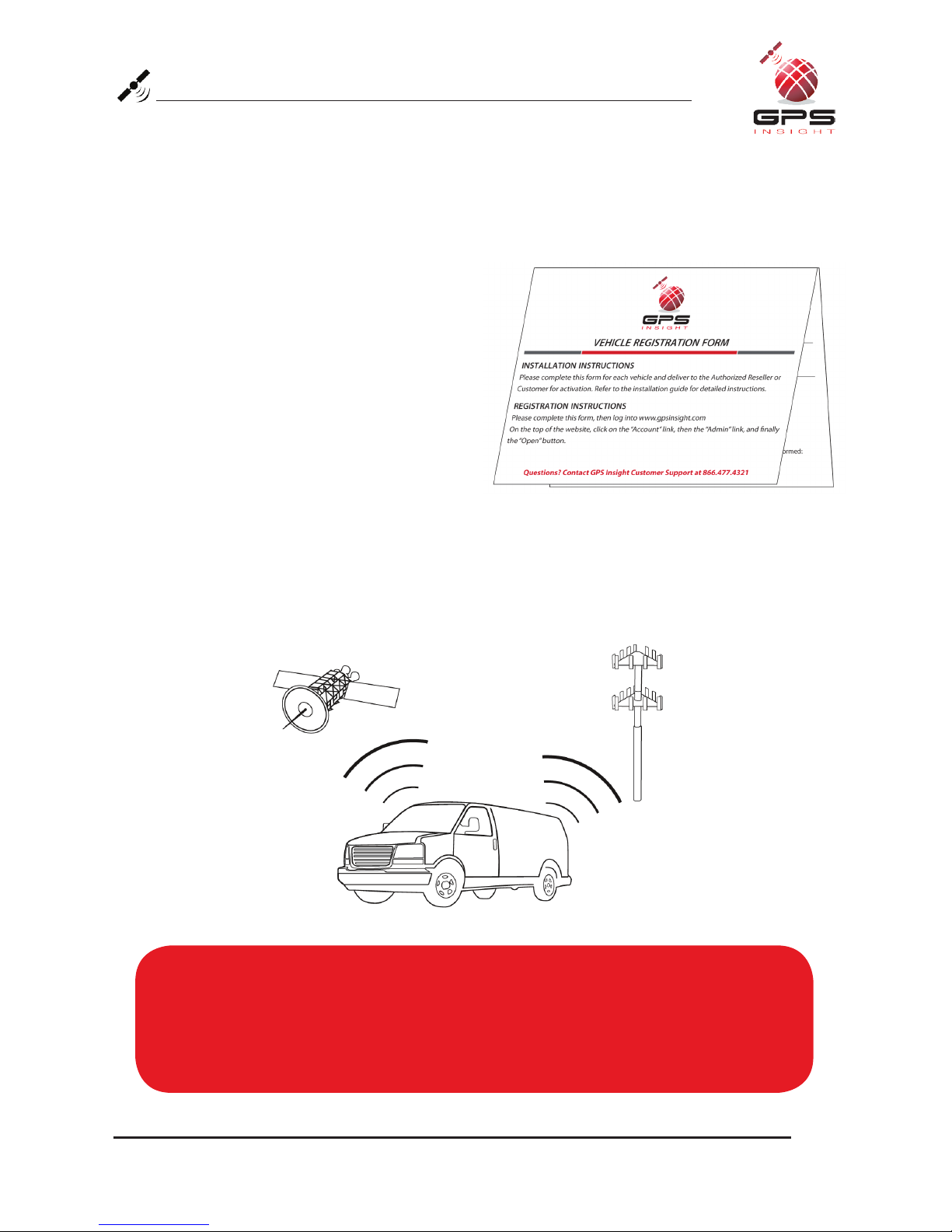
Registration Form
Fill out the enclosed registration form before completing installation.
Record the following information:
• Vehicle Identification Number (VIN)
• License Plate
• Year
• Make
• Model
• Unit’s Serial Number (10 digits)
1300915003
Installation Tip:
Metal walls and tall buildings may interfere with the reception from GPS satellites and
the cellular network. Perform installation when the vehicle is in clear view of the sky.
Conduct final installation verification after the vehicle has been running outside for
10–15 minutes.
www.gpsinsight.com | 866.GPS.4321 | support@gpsinsight.com
Page 4
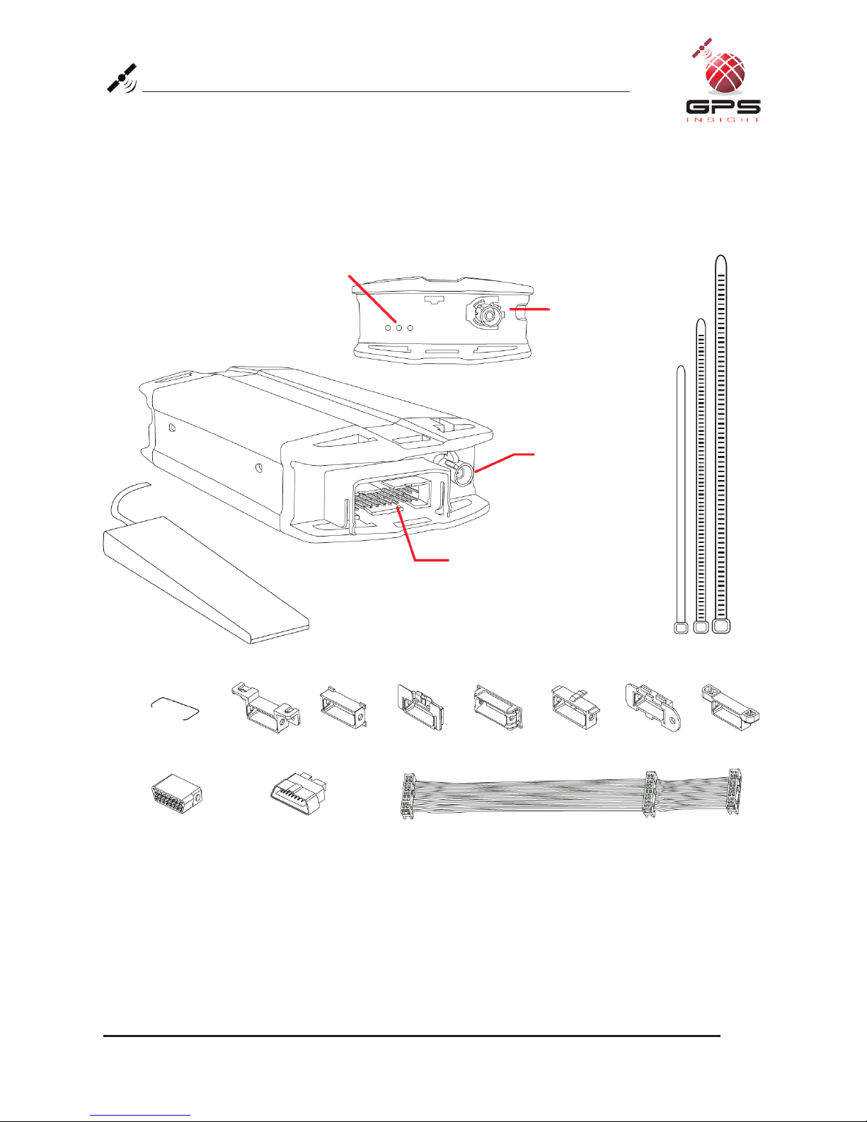
Light Duty (L3500) Unit Overview
Tie Wraps (X7)
Cellular Port
GPS Port
Data Port
LED Indicator Lights
Interior Glass-Mount Antenna
Back of Unit
Retainer Bar (X1)
Core Connectors (X1) Bypass Connector (X1) Harness Flat Cable (X1)
Harness Adapters (X7)
www.gpsinsight.com | 866.GPS.4321 | support@gpsinsight.com
Page 5
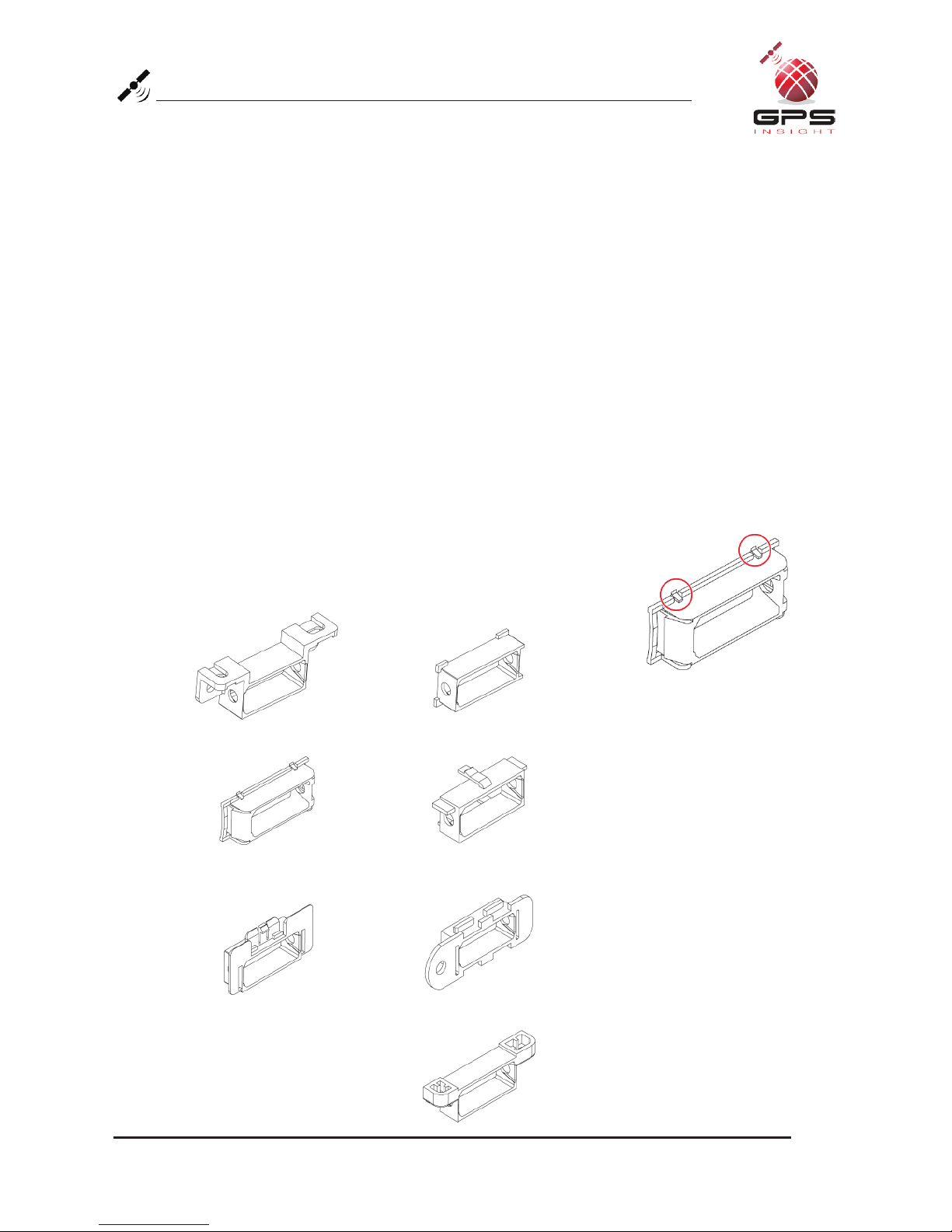
Harness Assembly Instructions
1. Select an Adapter
Select an adapter that most resembles the shape of the OBD-II port of the vehicle.
Use these guidelines to match an adapter (each adapter is stamped with a number) to the
vehicle it is most likely to fit.
• Ford, GM (1) or (6)
• Honda, Lexus, Toyota, Chrysler (2)
• Toyota*, Chrysler* (2a)
• GM, Saturn (3)
• Mercedes, BMW (4)
• Porsche, Audi, Volkswagen (5)
• Volvo (6)
• Saab (7)
* For certain Toyota and Chrysler vehicles, you may need to adjust the #2 adapter by
removing the clips on the top and bottom of the adapter.
To the right is an example of the adjusted adapter labeled (2a):
(2a)
(4)
(5)
(6)
(7)
(1)
(2)
(3)

www.gpsinsight.com | 866.GPS.4321 | support@gpsinsight.com
Page 6
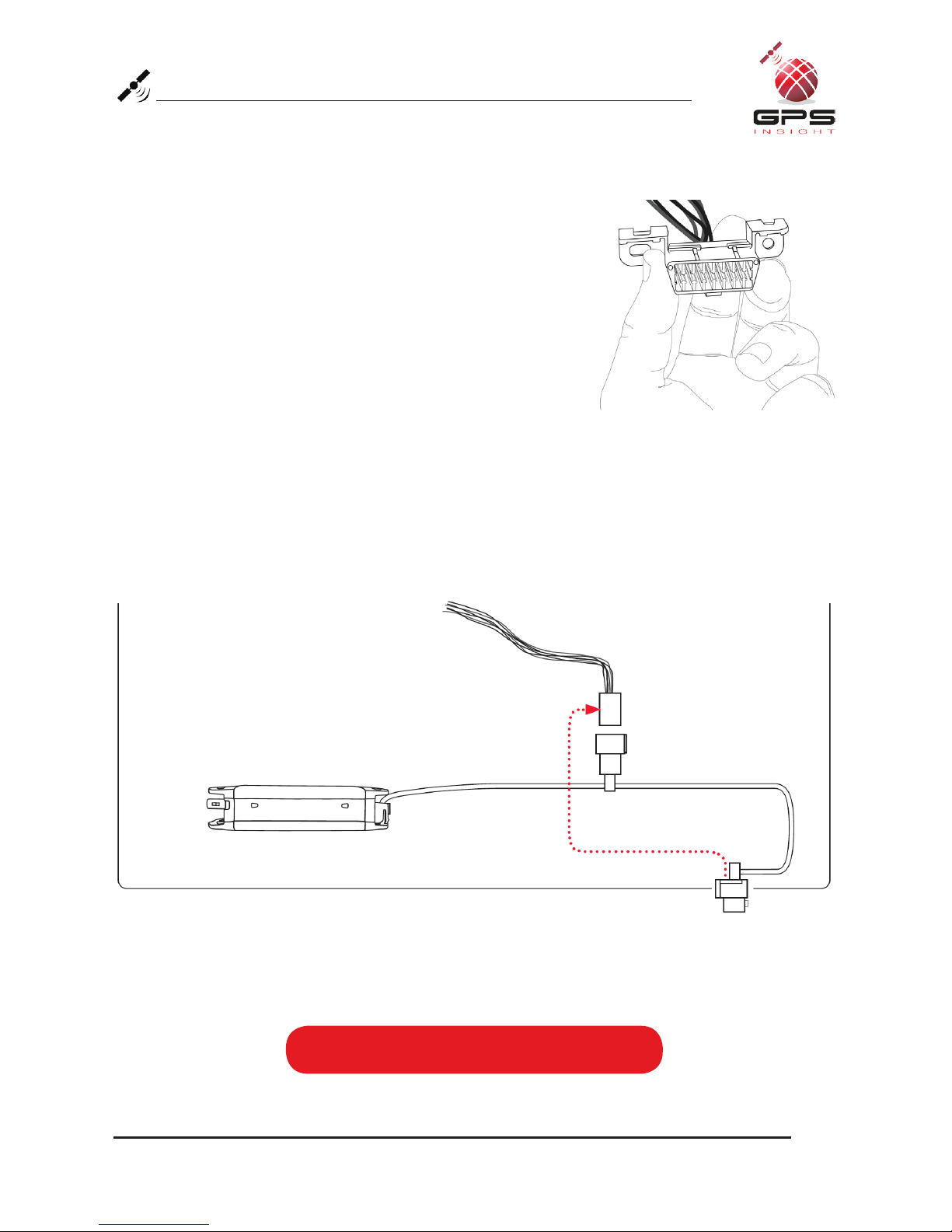
Adapter
Retainer Bar
OBD-II
Replacement
Connector
Core Connector
3500 Unit
Data Port
Harness Connector
Yellow Zip Tie
Details on page 17
Bypass
Connector
Installation Tip:
Please note that the key on the Harness Connector of the Harness Flat Cable must
be facing toward the top of the 3500 device to properly connect.
Connecting the Harness and Unit
1. Core Connector Assembly
1. Snap the selected plastic adapter to the back of
the Core Connector.
2. Attach the Core Connector to the OBD-II
Replacement Connector.
3. Use a Retainer Bar to secure the Core
Connector.
2. Data Port Connection
1. Connect the Harness Connector to the
Data Port Interface.
2. Use a yellow zip tie to secure the connection.
www.gpsinsight.com | 866.GPS.4321 | support@gpsinsight.com
Page 7
Connecting to the OBD-II Port
1. With the vehicle’s engine OFF, remove the OBD-II port.
• The OBD-II Connector may be hidden behind a hush
panel.
• To remove the connector, you may need to remove
screws or depress the clips.
2. Connect the Bypass Connector to the vehicle OBD-II port
that was previously removed.
3. Attach the Core Connector to the position where the
original OBD-II connector was installed. Secure it with
the screws or clips removed from the OBD-II Connector’s
original position (if applicable).
3500 Unit
Dashboard
Core Connector
Bypass Connector
Original OBD-II Port
To Vehicle
To complete installation proceed to page 13

www.gpsinsight.com | 866.GPS.4321 | support@gpsinsight.com
Page 8
Heavy Duty (H3500) Unit Overview
9-Pin Harness (X1)
Core
Connector
Bypass
Connector
Data Port
GPS Port
Cellular Port
Back of Unit
LED Indicator Lights
6-Pin Harness (X1)
Tie Wraps (X7)
Interior Glass-Mount Antenna
 Loading...