

www.gpsinsight.com | 866.GPS.4321 | support@gpsinsight.com
Internal Antenna Only
GPSI-3900 Installation Guide

www.gpsinsight.com | 866.GPS.4321 | support@gpsinsight.com
Page 2
Installation
First, verify that the power is configured correctly. It is essential that the power input (red wire)
be connected to a constant (un-switched) +12 VDC or +24 VDC supply and that the ignition
input (white wire) is connected to the vehicle ignition (switched) or another appropriate key
operated line (must be ignition-based circuit, not accessory). Failure to do so may result in
discharge of the vehicle battery.
The ground line (black wire) must be connected to chassis ground.
Placement of the GPS device is critical to proper operation of the GPSI-3900. Find a discreet
location for the placement of the tracker. The tracker has an internal GPS antenna and requires
the device have a clear view to the sky. Steel, iron, copper, and metal oxide windshields all
block GPS signals from reaching the tracker and cause the tracker to not function properly. The
best place to install the tracker is high inside the dashboard, white sticker side up, as close to
the dashboard plastic as possible. Plastics, wood, and regular glass do not interfere with GPS
signals and the tracker will operate normally if it is covered by any of these materials.
It is recommended that the device be installed with the white label facing up to ensure the
greatest possible GPS signal.
www.gpsinsight.com | 866.GPS.4321 | support@gpsinsight.com
Page 3
Installation (continued)
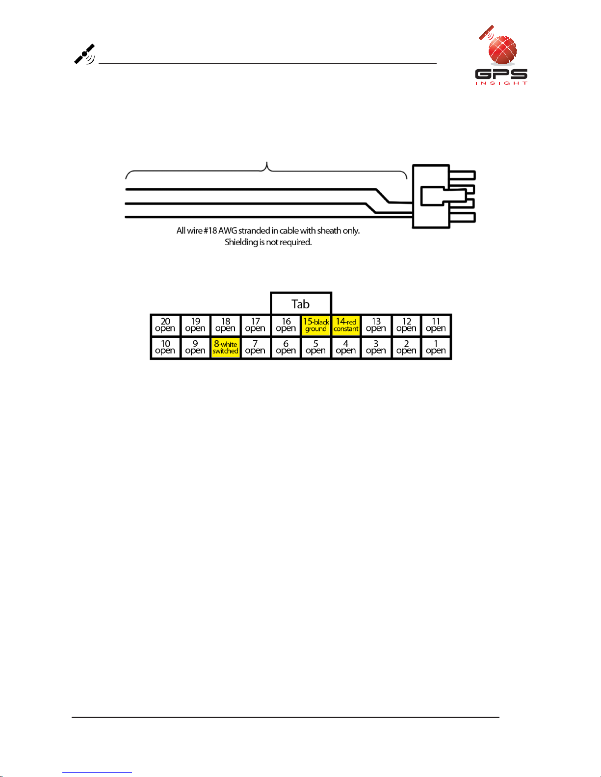
Standard Wiring Harness:
Red Wire = constant +12V
White Wire = switched +12V (+12V w/ ignition on, 0V w/ ignition off)
Black Wire = ground

www.gpsinsight.com | 866.GPS.4321 | support@gpsinsight.com
Page 4
Installation Verication
Upon successful installation of a GPSI-3900 both the GPS and Cellular lights will remain
on. There are 2 LEDs on the back of the device, solid green (GPS) and solid amber
(Cellular) indicate a good GPS and Cellular fix. A flashing GPS or Cellular light indicates
that the GPSI-3900 is searching for the corresponding signal. If the installation is taking
place in an area with limited view of the sky a GPS “lock” isn’t expected until such time as
the unit is able to see at least 3 satellites. It’s recommended that the vehicle be driven for
a minimum of 10 minutes before verifying a successful installation.

www.gpsinsight.com | 866.GPS.4321 | support@gpsinsight.com
Page 5
Environmental Specications
The GPSI-3900 is designed to operate in environments typically encountered by fleet
vehicles, including wide temperature extremes, voltage transients, and potential
interference from other vehicle equipment.
To ensure proper operation in such an environment, GPSI-3900s were subjected to
standard tests defined by the Society of Automotive Engineers (SAE). The specific tests
included temperature, shock, vibration, and EMI/EMC. These tests were performed by
independent labs and documented in a detailed test report. In accordance with Appendix
A of SAE J1113 Part 1, the Unit is considered a “Functional Status Class B, Performance
Region II” system that requires Threat Level 3 Testing.
The following is environmental conditions the GPSI-3900 is designed to operate in and
the relevant SAE tests that were performed. No formal altitude tests were conducted.
Temperature
CDMA2000 1x Operating Temperature Range: -20° C to 60° C
GSM Operating Temperature Range: -30° C to 60° C
iDEN Operating Temperature Range: -25° C to 60° C
Storage Temperature Range: -40° C to 85° C
SAE Test: SAE J1455
Humidity
5% to 95% relative humidity, non-condensing, SAE Test: SAE J1455
Altitude
Operates at altitudes of up to 10,000 feet and can be stored safely up to 40,000 feet
Shock and Vibration
Ground vehicle environment with associated shock and vibration
SAE Test: SAE J1455, Mil Standard 202G and 810F
Bench-Handling (Non-Operating)
4 inch pivot drops on each of the faces on which it may be placed for servicing
or installation
SAE Test: SAE J1455, Mil Standard 810F
Electromagnetic Compatibility (EMC)
EMC compliant for a ground vehicle environment
SAE Test: SAE J1113 Parts 2, 12, 21 and 41
RF Connector
The GPSI-3900’s RF connector is SMC - the impedance is 50 Ohms nominal

www.gpsinsight.com | 866.GPS.4321 | support@gpsinsight.com
Page 6
Environmental Specications (continued)
Operating Voltage Range
The GPSI-3900 supports vehicles with 12 or 24 VDC systems including transients and
electrical system noise; this includes ranges from 8.5 to 30 VDC
SAE Test: SAE J1455
Transient Protection
Input voltage transients typical of large trucks
SAE Test: SAE J1113 Part 11
Electrostatic Discharge (ESD)
No damage or performance degradation after the ESD disturbance
SAE Test: SAE J1113 Part 13
Power Consumption
Average: 100mA at 13.8 VDC
Peak: 200mA for 50ms transmit burst (0.1% transmit duty cycle typical)
Stand By 10mA
GPS Receiver
16 channel GPS receiver
Accuracy: 5 meter CEP (with SA off), Antenna connector: SMA
Note that the GPSI-3900 requires an antenna amplifier that operates at 3VDC;
5VDC amps will not work
Available Radio Interfaces
CDMA 1xRTT, GPRS, iDEN
Physical Specications
Size
4.0” L x 2.0” W x 0.85” H (102mm x 51mm x 22mm)
Weight
0.11 lbs (1.75oz)


www.gpsinsight.com | 866.GPS.4321 | support@gpsinsight.com
GPS Insight offers 24/7/365 Customer Support
Please contact us today if you have any additional questions about this product.
Toll Free: 1.866.477.4321
Email: support@gpsinsight.com
Web: www.gpsinsight.com
 Loading...