

Iridium Tracker
I
NSTALLATION
M
ANUAL
I
RIDIUM
T
RACKER
V
ERSION
3.3


1 General Safety Instructions
• Attention! You must read this installation manual before starting the installation!
• The Workshop / Company that is responsible for the initial installation must guarantee the proper installation for at
least 12 months
• Before beginning the installation of your product, qualified personnel (skilled in electronic/electrical installation) must
read completely this guideline. Important information contained herein is to prevent danger and damages of the used
product or vehicle.
• Do not disassemble the device. Do not touch before unplugging the power supply if the device is damaged, the power
supply cables are not isolated or the isolation is damaged.
• All wireless data transferring devices produce interference that may affect other devices which are placed nearby.
• The device may be connected only by qualified individuals.
• The device must be firmly fastened in the predefined location.
• Warning!! May explode, if wrong accumulator is used.
• Any installation and/or handling during a lightning storm is prohibited.
• The device is susceptible to water, humidity and too much heat.
• All installations have to be completed with a function test according this manual. Instructions must not be ignored (e.g.
missing permanent power or connection to ignition) and wrong installations will cause the need of a new installation
date.
1.1 Conctact
Europe und International
Mid
dle East
Software
-
Management GmbH
Raiffeisenplatz 1/3c
A-4863 Seewalchen am Attersee
Austria
Tel: +43-7662 22 3 44
Fax: +43-7662-22 3 44 30
Office hours: Mo – Thu 8 – 12 and 13 – 17, Fr 8 - 12
www.gps.at
info@gps.at
High-Tech Solutions FZ
-
LLC
Branch office Dubai Internet City
Building 1 - Office 10 (Ground Floor)
P.O. Box 502721, Dubai
United Arab Emirates
Tel: (+971) 4 4330906
Fax: (+971) 4 4234915
Office hours: Sun – Thu 9 - 18
www.gps.at
info@gps.at
1.2 Partner Data Recording-Tool
To test the installation an online tool was developed. Before the Test, the data recorder has to be started!
The recorded data is available by calling a link, also the digital inputs trigger an email. The recording ends after 24h
automatically. The tool works for all devices, that send data by a data connection. SMS is not supported. Please note that
different hardware types send data differently.
https://service.sw-management.at/BoxServer/partneradmin/
Please note that
• The username and password will be given by us. Please contact us via phone or email to get the username and password!
• The IMEI must be entered 100% correctly. Also the email is necessary to get events and to get the list per email!

After you entered a valid IMEI:
Click on the link to see the data. You can also use this link on a smartphone or tablet, if you do the installation in the vehicle!
Installation is only complete if the following mandatory test results are accomplished successfully:
TS (Timestamp): Current data is shown (check ts coloum for the timing, be aware of time zone differences, it uses
Lat / Lon /Alt (GPS Position): the gps position and altitude is shown, you could check the values by entering them in
Google Maps.
Speed: when driving speed is higher than 0.
Dig In 1 (Digital Input 1) must be 1if ignition is ON (only if ignition signal is connected to digital input 1)
Dig In 1 (Digital Input 1) must be 0 if ignition is OFF (only if ignition signal is connected to digital input 1)
Certain accessories are also shown
Drivercode: if an iButton is connected to the reader, there will be
1.3 SIM Cards (usually already in the device)
Refer to your vendor for SIM card related issues. It could be that the SIM card is already activated and inserted in the tracking
device. The right SIM cards must be available for starting installation. The partner / customer is responsible for acquiring the
right SIM card. The SIM card must fulfill special requirements (refer to UserManual). The tracking units only work with the SIM
card and operator that has been configured on the tracking unit (GSM operator, country). SIM card should be inserted in the
module while the connector is plugged off (while module has no power).

Make sure that
GSM number of the SIM card is labeled on the box
SIM card PIN has been deactivated
SIM cards have been tested in a mobile phone (SMS and GPRS must work in a mobile phone)
If SIM card checks fail, you cannot complete installation.
For inserting the SIM card you must unscrew/open the box and place the SIM card in the SIM card holder in the right direction.
1.4
Mounting Recommendations
1.4.1 Vehicle Tracker
• When connecting the connection (2x10) cables to the vehicle, the
appropriate jumpers of the power supply of the vehicle should be
disconnected.
• Before dismounting the device from the vehicle, the (2x10)
connection must be disconnected.
• The device is designed to mount in a zone of limited access,
which is inaccessible for the driver. All related devices must meet
the requirements of standard EN 60950-1.
• Before usage, the device should be placed so that its LED
indicators are visible, which show the status of operation the
device is ON.
• As any electrical device the tracking unit is susceptible to
humidity or too much heat. Placing it safely under the dashboard
should be a safe.
1.4.2 Mobile Tracker & Container Tracker
In this case it is only necessary that the device can face the satelite!
1.5 Connecting Wires
If there are cables to connect, the following rules apply:
• Wires should be connected while module is not plugged in.
• Wires should be fastened to the other wires or non-moving parts. Try to avoid heat emitting and moving objects near
the wires.
• The connections should not be seen very clearly. If factory isolation was removed while connecting wires, it should be
applied again.
• If the wires are placed in the exterior or in places where they can be damaged or exposed to heat, humidity, dirt, etc.,
additional isolation should be applied.
• Wires cannot be connected to the board computers or control units
• If unused, insulate the ends properly to ensure that the unused cables do not short to anything in the vehicle or any
other cables.
1.6 Connecting the Power Source / Ground
If a power must be connected, the following rules apply:
• Permanent stable power is very important to operate the device.
• It is recommended to connect to the main power cable in the fuse box.
• Don’t take the power source from the radio as this might affect the quality of your radio.
• Be sure that after the car computer falls asleep, power is still available on chosen wire. Depending on a car, this may
happen in 5 to 30 minutes period.
• When module is connected, be sure to measure voltage again if it did not decrease.
• If power cable of the device is connected to ignition, this impacts the quality of tracking as down-times (device is off
power) will occur. Connecting power supply to ignition might only be necessary in case the vehicle’s battery is too
weak and depleted fast.
• In some cases the box installation caused a radio noise effect. Don’t take the power source from the radio. You can
avoid this noise by re-locating the box and the antennas far away from the radio.
1.7 Anschluss Zündungskontakt
Sollte ein Anschluss an der Zündung gefordert sein, gelten folgenden Regeln:
• Stellen Sie sicher, dass es wirklich das Zündungssignal ist (kein Spannungsabfall während Start)
• Stellen Sie sicher, die Box auch mit Strom versorgt wird, wenn die Zündung aus ist.

• Stellen Sie sicher, dass das Zündungsplus nach Abschalten der Zündung tatsächlich 0 ist.
1.8 GPS Antenna
If the device has a GPS antenna, the following rules apply:
• When placing antennas avoid easily reached places. Hide antennas
UNDER the dashboard if possible.
• Please place the GPS-antenna on the dash-board in order to check
the box during installation. After you have got a correct GPS fix you
can fix it.
• Make sure that the GPS reception of the position is good (no metal
shielding). Not all antennas are optimal for hiding them.
• Avoid GPS antenna placement under metal surfaces.
• GPS antenna must be placed so its state is as horizontal as possible
(if antenna is leant more than 30 degrees, it is considered incorrect
mounting).
• GPS antenna cable cannot be bent more than 80 degrees.
• GPS antenna must be placed sticker facing down.
• It is recommended to place GPS antenna behind or under
dashboard as close to the window as possible. A good example of
GPS antenna placement is displayed in a picture below (below area
colored green).
• If you need accurate GPS data and want to reduce the time to GPS-
Fix, the antenna should be mounted on the dashboard.
Important notice regarding position of GPS Antenna:
Hiding the GPS antenna below the dashboard (near to the front
window) is generally possible according to the producer and must
be tested for each vehicle. Under certain circumstances hiding the
antenna will deteriorate the GPS Fix (the quality of the GPS
position) and could lead to higher power consumption (search for
GPS).
1.9 GSM Antenna
If the device has a GSM antenna, the following rules apply:
• GSM antenna must be placed with as little metal obstacles around it as possible.
• Avoid placing GSM antenna near car radio, speakers or alarm systems.
• After hiding it, a test of GSM/GPRS connection must be done.
Important notice regarding position of GSM/GPRS Antenna:
• Avoid connections that could cause interference with radio, speakers or alarm systems.
1.10 Power Consumption
Please note that external factors might cause the box to enter sleep mode (searching for GPS, reloading batteries).
Different factors (box operations, antenna positions) will cause different power consumption.
To avoid total battery depletion after very long inactivity you can add a main power switch that can be installed hidden so
that you can disconnect the device from power if needed.
1.11 Installation Tests
Test must be done outside to have a GPS connection. All tests must be done according the instruction.
For devices installed in vehicles:
• Drive 500 meters, switch off the ignition for minutes, switch it on again and driver back and stop in front of the
workshop if possible.
• Verify your test using the online data tool
For mobile trackers:
• Trigger some data points outside
• Verify your test using the online data tool

1.12 General Trouble-Shooting
Sometimes in rare case, if happen that devices are not sending or send not as expected.
For devices installed in vehicles the reasons might be:
• Loose cables or damaged cables
• Wrongly fixed, damaged or moved or slipped antennas
• Wrongly connected permanent power
• Wrongly connected or not connected ignition
• A damaged antenna or device or cut cable
For mobile trackers the reasons might be:
• Battery
• A damaged device
1.13 Damaged Device / RMA
If a device is damaged, it must be sent back with the SIM card with a completely filled out RMA form. Without the RMA form the
device will be processed. The RMA form can be found on www.gps.at
1.14 Documentation
After finishing your installation and tests you should send a Installation Document to your customer/partner:
For a better overview the list of installed vehicles shall be summarized and handed over. Please send us a list with all the
vehicles, SIM-Card-numbers and IMEI.
IMEI of Box GSM number Vehicle name Odometer Odometer Reading
Date
Location of box /
special remarks
We recommend to fill in the vehicle service for every installation. It is an approval document that the installation was tested.
You can download it here:
http://www.gps.at/downloads/vehicle_service_form.doc

2 Installation of the Iridium Container Tracking Unit
The Iridium Container Tracking Unit will be activated for Iridium SBD Data and for the GPS Fleet Software by the seller before
releasing it to you. The CONTAINER TRACKING UNIT shall be installed in horizontal position onto a (ferro) steel surface with no
obstructions to the sky above. As soon as the CONTAINER TRACKING UNIT is mounted onto ferrous metal, it will be switched on
automatically. If the unit is provided with magnets, be aware. These magnets are very strong!!! The CONTAINER TRACKING UNIT
will send a first GPS position immediately to confirm the unit is switched on and working.
Please note that it can take several minutes before a message from the unit is received (depending on satellites in sight). GPS
takes typically 40..50 seconds for a cold start fix. Latency in the Iridium Network is very low. Typical values measured 12 .. 15
seconds. When the CONTAINER TRACKING UNIT is removed from ferrous metal, it will be triggered to send another message. As
soon as the last message is sent, the CONTAINER TRACKING UNIT will switch into the power-down state again (factory powerdown state).
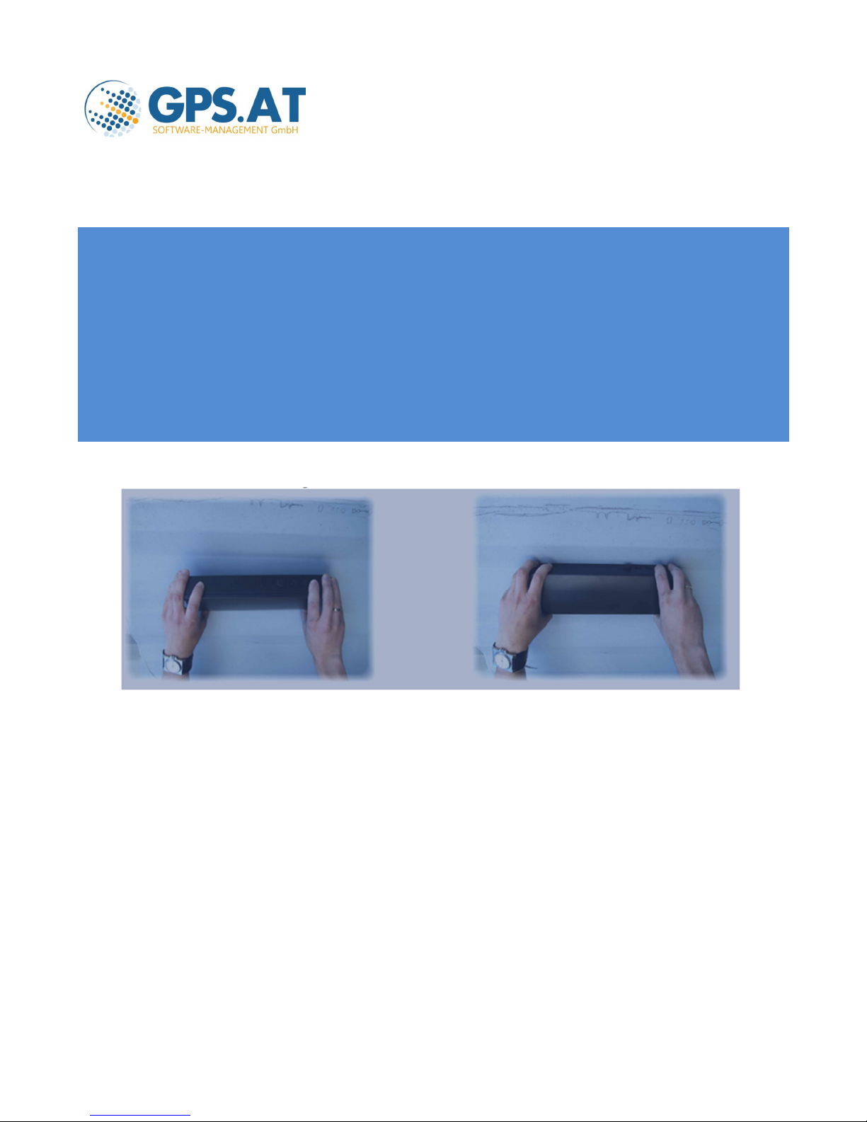
2.1 Installation with Magnets
Holding the CONTAINER TRACKING UNIT with both hands, hold it over the area where it shall be placed. Tilt the unit appr. 45
degrees as shown in figure below. Then lower it onto the steel surface and turn the unit until the magnets make contact with
the steel surface. Try to do this as controlled as possible to avoid a ‘slam’ and keep your fingers free from the CONTAINER
TRACKING UNIT surface contact area. Slamming the unit onto the steel surface could cause damage due to extreme G-forces
that might occur. Reverse this procedure to remove an unit. Never try to slide a unit. This will damage the magnetic’s corrosion
protective coating and the steel (paint) surface it is mounted on.
2.2 Installation with screw mounting
If the CONTAINER TRACKING UNIT should be installed using 4 pieces M5 bolts, the bolts shall not be longer then 18mm plus the
steel surface thickness. Drill 4 holes Ø 5,5 mm according the drill plan. See figure below. X is steel surface thickness Bolt M5
maximum length is X+18 mm

2.3 Battery life
The CONTAINER TRACKING UNIT is equipped with a 7.2 Volts / 36Ah Lithium-Thionyl-Chloride battery. Contradictory to other
batteries e.g. alkaline or so, is that the cell voltage does not drop if the battery wears and therefore it is difficult to measure the
actual battery conditions. Taking in count the self-discharge of the battery, average time to get a GPS fix and the average time
needed on the Iridium network to send a message, a prognoses of the battery life span related to several reporting time interval
was calculated. Rule of thumb is that 3650 reports can be send on one battery:
8 reports and a total of 16 positions per day battery life span 3.2 years
4 reports and a total of 8 positions per day battery life span 4.2 years
2 reports and a total of 4 positions per day battery life span 5.0 years
1 reports and a total of1 position per day battery life span 10 years
2.4 Replacement of the battery
If the battery needs to be replaced, we advice to return the CONTAINER TRACKING UNIT to the seller. Along with the battery,
the gasket in the lid of the unit, shall also be replaced to ensure optimum moisture ingress protection.
Data Values
Description
Physical
Size
Weight
Optional Magnets Weight
Magnets Holding Force
350x100x50 mm
1250 gr.
180
1080 N (~108 Kg)
Environmental
Operating Temperature
-35..+65 C
Humidity
Relative 100%
Electrical
Battery
7.2V / 36000mAh
Power
consumption
Sleep: 216 uA
Estimated nr. of
transmissions from 1
battery
3650
Sensors
Motion Sensor
used to control reporting frequency
Ferro Detector
used as turn on/off switch and
removal/sabotage detector
Satellite
Iridium Constellation
True Global Coverage
GPS Accuracy
20 channels Sirf III
1.8 m CEP(95)
3 Trouble-Shooting
Also read the section trouble-shooting in the first section of this document!
 Loading...