

Page 1
1
www.trackmaker.com
Page 2
Summary
Summary .................................................................................................................................................................... 2
1 Preliminary ............................................................................................................................................................ 6
1.1 What is GPS TrackMaker® ...................................................................................................................................... 6
1.2 Hardware Key ......................................................................................................................................................... 8
1.3 License Agreement for GPS TrackMaker® Program ................................................................................................... 9
2 Files Management ............................................................................................................................................... 12
2.1 Merging Files in GPS TrackMaker® ........................................................................................................................ 12
2.2 Files in GTM Format .............................................................................................................................................. 13
2.3 Files in GTZ or GZ Format ..................................................................................................................................... 14
2.4 Files in Text Format .............................................................................................................................................. 14
2.5 GPX File Format .................................................................................................................................................... 17
2.6 Importing GeoTiff Images ..................................................................................................................................... 17
2.7 Importing DRG Images ......................................................................................................................................... 18
2.8 Importing DXF Files (AutoCad®) ........................................................................................................................... 19
2.9 Exporting DXF Files (AutoCad®) ............................................................................................................................ 20
2.10 Importing Shapefiles (ArcView®) ......................................................................................................................... 22
2.11 Exporting Shapefiles (ArcView®) ......................................................................................................................... 23
2.12 Exporting XLS Files (MS Excel®) .......................................................................................................................... 24
2.13 Exporting DBF Files (dBase®) .............................................................................................................................. 25
2.14 Importing and Exporting Files in PCX5 Format ...................................................................................................... 26
2.15 Importing Files in E00 Format .............................................................................................................................. 27
2.16 Importing MIF/MID Files (MapInfo®) ................................................................................................................... 28
2.17 Exporting MIF/MID Files of MapInfo® .................................................................................................................. 29
2.18 Files Saved in Multi Media Cards (MMC and SD) .................................................................................................... 30
2.19 Data Import Tool ................................................................................................................................................ 31
2.20 Converting Blocks of Files .................................................................................................................................... 33
2.21 Automatic File Backup ......................................................................................................................................... 33
3 Waypoints ........................................................................................................................................................... 34
3.1 Creating, Editing and Deleting Waypoints ............................................................................................................... 34
3.2 Editing Waypoint Styles ........................................................................................................................................ 37
3.3 Selection of Waypoints Through Icons .................................................................................................................... 39
3.4 Modifying Several Waypoints at the Same Time ...................................................................................................... 39
3.5 Treating Repeated Waypoints ................................................................................................................................ 40
3.6 Converting Waypoint Text to Lowercase ................................................................................................................. 41
4 Tracklogs ............................................................................................................................................................. 42
4.1 Creating, Editing and Deleting Tracklogs ................................................................................................................ 42
4.2 Selecting Tracklogs by Style .................................................................................................................................. 47
4.3 Editing Several Tracklogs at the Same Time ........................................................................................................... 48
4.4 Reducing Tracklog Size ......................................................................................................................................... 50
4.5 Showing Tracklogs by Colors ................................................................................................................................. 51
4.6 Tracklog Union Tool ............................................................................................................................................. 51
4.7 Uniting Tracklogs and Routes with the Drawing Tools ............................................................................................. 52
4.8 Selecting Repeated Tracklogs ................................................................................................................................ 53
4.9 Scalable Tracklogs ................................................................................................................................................ 53
4.10 Fragment Tracklog Tool ...................................................................................................................................... 54
4.11 Applying Altitudes in Contour Lines ..................................................................................................................... 54
4.12 Creating Altitude Profile Starting From Contour Lines ........................................................................................... 55
4.13 Vector Drawing Tools .......................................................................................................................................... 56
4.14 Tracklog Labeling ................................................................................................................................................ 58
5 Routes ................................................................................................................................................................. 59
5.1 Creating, Editing and Deleting Routes .................................................................................................................... 59
5.2 Selecting Waypoints far from Routes ...................................................................................................................... 62
6 Maps .................................................................................................................................................................... 63
6.1 Overview .............................................................................................................................................................. 63
6.2 Accuracy of MAP Files ........................................................................................................................................... 64
6.3 Homogenizing Points of Tracklogs .......................................................................................................................... 65
6.4 Creating MAP Files ................................................................................................................................................ 66
6.5 Configuring Map Properties .................................................................................................................................... 67
6.6 Creating and Registering Projects of Maps .............................................................................................................. 69
2
Page 3

6.7 Editing Projects of Maps ........................................................................................................................................ 70
6.8 Removing Projects of Maps .................................................................................................................................... 71
6.9 Detection of Elements ........................................................................................................................................... 71
6.10 Optimizing Map Speed ......................................................................................................................................... 71
6.11 Protecting Projects of Maps ................................................................................................................................. 71
6.12 Maps in Gray Scale .............................................................................................................................................. 71
7 Manipulating Data ............................................................................................................................................... 72
7.1 Cutting Data ......................................................................................................................................................... 72
7.2 Copying Data ........................................................................................................................................................ 72
7.3 Pasting Data ........................................................................................................................................................ 72
7.4 Pasting an Image on Screen .................................................................................................................................. 73
7.5 Dragging Tracklogs, Routes and Waypoints with the Mouse ................................................................................... 73
7.6 Undo the Last Action ............................................................................................................................................ 73
7.7 Finding and Replacing Data .................................................................................................................................. 74
7.8 Rotating Waypoints, Tracklogs and Routes ............................................................................................................. 75
7.9 Data Edition in Table ............................................................................................................................................ 76
7.10 Reversing the Direction of Tracklogs and Routes ................................................................................................... 80
8 Special Functions ................................................................................................................................................ 81
8.1 Altitude Profile ...................................................................................................................................................... 81
8.2 Dragging the Screen ............................................................................................................................................. 84
8.3 Dragging Vertexes and Waypoints .......................................................................................................................... 84
8.4 Zoom Tools .......................................................................................................................................................... 85
8.5 Detecting Elements ............................................................................................................................................... 86
8.6 Selecting Data ...................................................................................................................................................... 87
8.7 Removing Accents ................................................................................................................................................. 89
8.8 Rectangular Clipping Tool ...................................................................................................................................... 90
8.9 Expanding Rectangular Zones ................................................................................................................................ 92
9 GPSTrackMaker's Configuration ......................................................................................................................... 93
9.1 Configuring the Behavior of the Program ................................................................................................................ 93
9.2 Choosing Grid and Background Color ..................................................................................................................... 95
9.3 Choosing the Communication Port ......................................................................................................................... 96
9.4 Configuring the Data Shown by the Mouse ............................................................................................................ 97
9.5 Configuring the Length Unit of Measurement ......................................................................................................... 98
9.6 Configuring the Speed Unit .................................................................................................................................... 99
9.7 Configuring the Surface Unit of Measurement ...................................................................................................... 100
9.8 Configuring the Azimuth Angle ............................................................................................................................. 101
9.9 Configuring Local Time ........................................................................................................................................ 101
9.10 Configuring the Coordinate System ..................................................................................................................... 102
9.11 True Grid Mode ................................................................................................................................................. 105
9.12 Configuring Images ........................................................................................................................................... 107
9.13 Configuring the Altitude Profile ........................................................................................................................... 109
9.14 Configuring the Datum ...................................................................................................................................... 110
9.15 Datum Defined by User .................................................................................................................................... 112
9.16 Grid Defined by User ......................................................................................................................................... 113
9.17 Displaying Grid Lines ......................................................................................................................................... 114
9.18 Showing Scale on Screen ................................................................................................................................... 115
9.19 Changing the Language ..................................................................................................................................... 115
10 Calculations with Tracklogs, Routes and Waypoints ...................................................................................... 116
10.1 Topographic Surface x Cartographic Surface ....................................................................................................... 116
10.2 Conversion to the Local Topographical Surface .................................................................................................. 118
10.3 Calculating Cartographic Length of Tracklogs and Routes .................................................................................... 121
10.4 Calculating Topographical lengths of Tracklogs and Routes .................................................................................. 122
10.5 Horizontal Length of Tracklogs and Routes ........................................................................................................ 123
10.6 Calculating Cartographic Areas .......................................................................................................................... 124
10.7 Calculating Topographical Areas ......................................................................................................................... 126
10.8 Estimate of Area Calculation Error Using Handheld GPS ....................................................................................... 128
10.9 Calculation of Arithmetic Average of the Points .................................................................................................. 129
10.10 Calculation of Maximum Difference of Altitudes ................................................................................................ 130
10.11 Speed and Total Time in Tracklogs ................................................................................................................... 130
10.12 UTM Scale Factor and Meridian Convergence ................................................................................................... 130
11 Inserting a Map's Image in Background ......................................................................................................... 131
11.1 General Information About Map Images ............................................................................................................. 131
3
Page 4

11.2 Rotating Images ................................................................................................................................................ 132
11.3 Calibrating Map Images ..................................................................................................................................... 133
11.4 Calibrating Images Through the Points of Extremities .......................................................................................... 137
11.5 Showing Image Properties ................................................................................................................................. 138
11.6 Bringing Image to Front ..................................................................................................................................... 139
11.7 Sending Image to back of the others ................................................................................................................. 139
11.8 Removing Images ............................................................................................................................................. 140
11.9 Saving the Image .............................................................................................................................................. 141
11.10 Clipping Images .............................................................................................................................................. 142
11.11 Restoring the Aspect Ratio of the Image ........................................................................................................... 142
12 Interface of GPS's Comunication .................................................................................................................... 143
12.1 Connecting the GPS to PC .................................................................................................................................. 143
12.2 Setting the PC Local Time Clock through GPS ..................................................................................................... 145
12.3 Sending and Receiving Waypoints, Tracklogs and Routes .................................................................................... 146
12.4 NMEA0183 Interface .......................................................................................................................................... 147
13 Real Time Navigation (RTN) ........................................................................................................................... 148
13.1 Activating Real Time Navigation (RTN) .............................................................................................................. 148
13.2 Manipulating the Screen in RTN Mode ................................................................................................................ 150
13.3 Configuring Real Time Navigation ...................................................................................................................... 151
13.4 Registering Waypoints in Real Time .................................................................................................................... 153
13.5 Simulating Real Time Navigation ........................................................................................................................ 153
13.6 Vehicular Tracking Interface ............................................................................................................................. 153
14 Printing Data ................................................................................................................................................... 154
14.1 Print Preview ..................................................................................................................................................... 154
14.2 Printing Data ..................................................................................................................................................... 155
14.3 Printing in Scale ................................................................................................................................................ 156
14.4 Configuring Printing ........................................................................................................................................... 157
14.5 Printing List of Data ........................................................................................................................................... 158
15 Catalog of Images ........................................................................................................................................... 159
15.1 Creating a Catalog of Images ............................................................................................................................ 159
15.2 Opening a Catalog from Disk .............................................................................................................................. 160
15.3 Uniting Several Catalogs .................................................................................................................................... 161
15.4 Saving the Catalog in Disk ................................................................................................................................ 161
15.5 Loading Images from Catalog ............................................................................................................................ 162
15.6 Showing on screen Images from Catalog ........................................................................................................... 162
16 Maps on the Word Wide Web .......................................................................................................................... 163
16.1 Accessing Maps on the World Wide Web ............................................................................................................. 163
16.2 Configuring Web Pages of Maps ......................................................................................................................... 164
16.3 Opening Maps in Google Earth® ........................................................................................................................ 165
16.4 Opening Images from Google Maps® ................................................................................................................ 166
17 Internal Tables ................................................................................................................................................ 167
17.1 Datum Table .................................................................................................................................................... 167
17.2 Internal Icon Table of GPS TrackMaker® ............................................................................................................ 173
4
Page 5

1 Preliminary
1.1 What is GPS TrackMaker®
The GPS TrackMaker® program for Windows® XP, Vista and Seven allows bi-directional data communications
between GPS receivers and your computer, including full data editing and storage options.
GPS means
Global Positioning System
; a system with more than 24 satellites in orbit that send information to the
Earth. GPS receivers can receive those signals continuously and, if receiving at least 3 satellites, the GPS calculates
the position and direction of travel on ground. The accuracy of the GPS information increases with the number of
satellites received.
Satellite data stored in the GPS receiver can be transferred to a PC as Waypoints, Tracklogs and Routes. The GPS
TrackMaker® program recognizes this data, allowing the User to edit them with a simple graphical interface.
The main features of GPS TrackMaker® program are:
• Fast vectorial background maps
• Communicates directly with many popular GPS receivers using your data cable and an available serial port.
• Creation, editing and deletion of Tracklogs, Waypoints and Routes on a graphical, easy-to-use interface.
• Internal database with more than 250 different parameters of map datum.
• Data can be edited and saved, using several vector file formats.
• Automatic Tracklog labeling.
• Insert digital images such as maps and photos directly onto the grid and use them for navigation over the chart, with full
zoom and drag features.
• Calculation of cartographic length, average and instant speeds on Tracklogs.
• Speed and length with several units of measurement.
• Zoom in, Zoom out and specific area Zoom functions.
• Move the whole drawing just by pressing the right mouse button.
• Management of more than 200 different color icons.
• Display Waypoints on screen in several different styles.
• Selectable colors for background, grid, Waypoints and Tracklogs.
• Allows selective deletion of data, either by exclusion or inclusion.
• GPS Macro function, specially created to eliminate Waypoints located away from a User’s defined Route; (Useful for those
who intend to travel using a GPS receiver).
• Files Recognition of Garmin® PCX5, Waypoint+, Map/Info, Arc/Info (E00) and others formats.
• Real Time Navigation (RTN) Function
• Map Catalog Function that allows you to easily create a digital catalog of maps.
•
Autoload
Function that allows you to load maps from the catalog in Real Time Navigation (RTN)
• Support for several rectangular coordinate systems, including UTM, British National Grid, Irish National Grid, Swiss Grid,
Swedish Grid, New Zealand Grid, Finnish Grid, Dutch Grid, etc.
•
True-Grid
mode that allows you to show rectangular coordinate systems without deformation.
• Support for filled and scaleable Tracklogs.
• Scalable Waypoint Text : the text increases or decreases with the scale.
• Support for date, Altitude and rotation in Waypoints.
• Support for date and altitude in Tracklogs.
• Functions
Undo, Copy, Cut
and
Paste
.
• Allows you to send only selected data to the GPS.
• Dragging of Waypoints, Tracklogs, Routes and Pictures using the mouse.
• Support for Garmin® handheld GPS.
• Support for Magellan® handheld GPS.
• Support for Lowrance/Eagle® handheld GPS.
• Support for GPS MLR® handheld GPS.
• Support for GPS Brunton®/Silva® handheld GPS.
• Support for
GTM Tracker
- GPS Vehicle Tracker
• NMEA0183 protocol for real time navigation.
• Support for several languages
5
Page 6

If you own GPS TrackMaker Professional®, you will also have specific functions for area calculation,
support for AutoCAD® DXF files, support for ArcView® Shapefiles, data treatment in tables, etc. Every
time that the symbol to the side appears, the functions are exclusive to GTM PRO®. They are not available
in the free version.
Additional functions in GTM PRO® include:
• Allows to create complete projects of maps.
• Advanced functions for professional use.
• Total support for images TIFF, PNG, BMP, JPG and GIF.
• Geocoded images GeoTiff and DRG
• Export map images to several raster formats
• Rotation and clipping of background images, allowing a better calibration
• Complete data editing in table sheets similar to Microsoft Excel®
• Calculation of azimuths with hundredth-second accuracy.
• Calculation of lengths with millimeter accuracy.
• Exclusive function
Expand Zone
that allows a better calibration of images
• Print Preview function
• Area calculation defined by Tracklogs in different measurement units.
• Local topographical area and cartographic area calculation.
• Local topographic length and cartographic length calculation.
• Length Calculation factoring altitude changes for the horizontal projection.
• Topographical conversion function for data obtained by a GPS device.
• Import and export data for AutoCAD®, in DXF format.
• Import and export data for ArcView®, in SHP format.
• Import and export data for MapInfo®, in MID/MIF format.
• Export data to XLS (Excel®) or DBF (dBase®) file formats.
• Import and export data for Microsoft Excel® and Microsoft Word®
• Creation of multiple Waypoint styles, to obtain more detailed maps.
• Exclusive background filled Tracklogs to be used with images.
• Datum defined by User.
• Rectangular Grid systems defined by user.
• LTM (Local Transverse Mercator) and RTM (Regional Transverse Mercator) grids.
• Exclusive Tracklog union tool.
• Exclusive Rectangular Clipping Tool
• Average calculation of the geodesic position from Waypoints, Tracklogs and Routes
• Calculation of horizontal distances and altitude differences.
• Data Rotation.
• Altitude Profile with advanced functions.
• Creation of Altitude Profile Tracklogs
• Support for Contour Lines
• Accents removal Tool
• Calculation of Scale Factor and UTM Meridian Convergence
• Multiple vehicle tracking at the same time.
• Detailed report of streets and avenues where the vehicle passed.
GPS TrackMaker® By Odilon Ferreira Junior
All rights reserved.
Geo Studio Technology Ltd.
Belo Horizonte – Minas Gerais – Brazil
www.trackmaker.com
6
Page 7
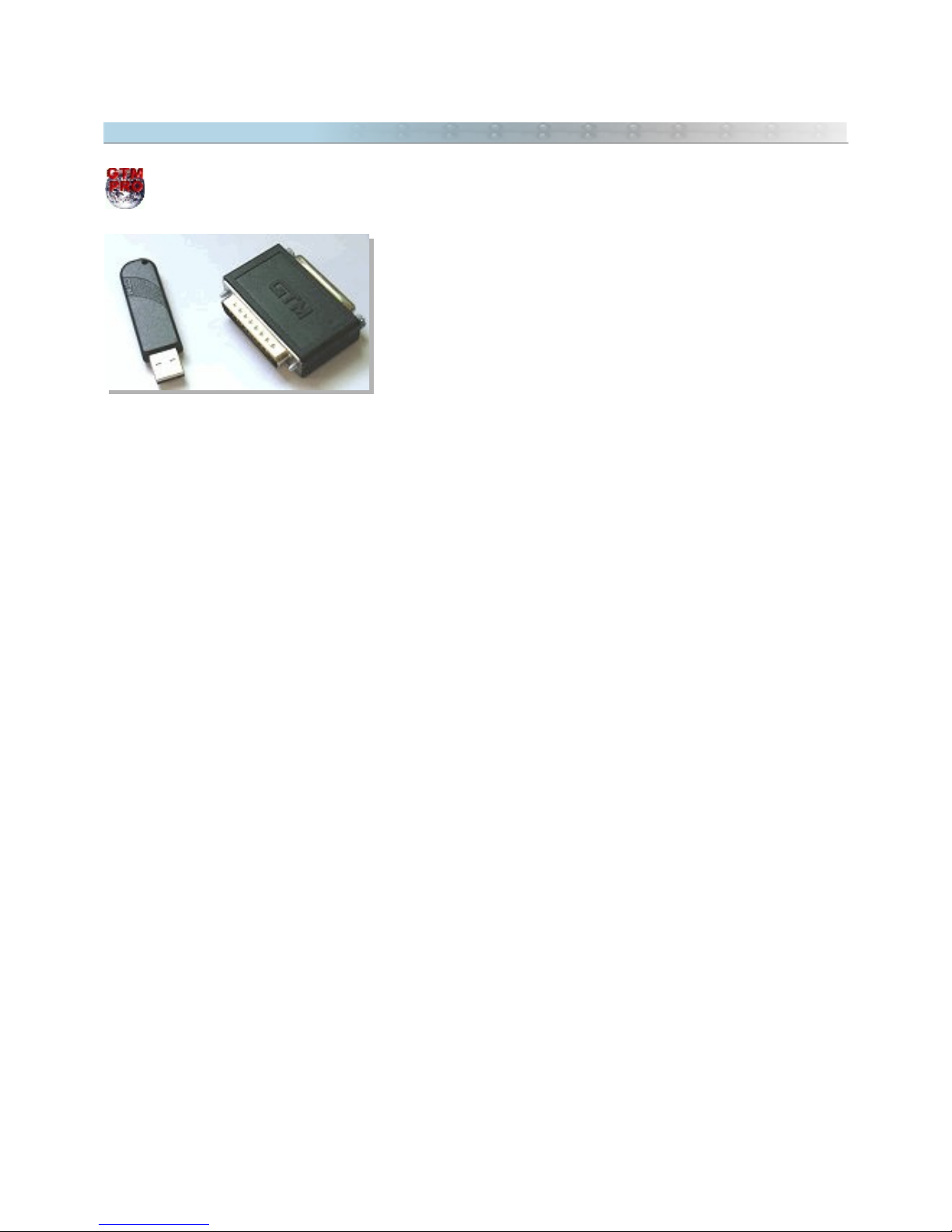
1.2 Hardware Key
The information below applies only to GTM PRO® Users.
The Hardware Key or
dongle
is an electronic plug that works as an
unlock password of the GTM PRO®. The plug is easily connected to
the printer port or USB port, and must be present when GPS
TrackMaker Professional® is being executed.
The plug doesn't interfere in the operation of printers, scanners or
other devices.
The license by Hardware Key is used by GPS TrackMaker Professional® 4.0 or above.
To purchase the Hardware Key, please contact the store where you purchased GTM PRO® or the Author at
www.trackmaker.com
7
Page 8

1.3 License Agreement for GPS TrackMaker® Program
When installing or using this program, the User agrees to accept all terms and conditions of this license
agreement. If the User does not agree with all conditions, he must uninstall the program using the
Add or Remove
Programs
tool in the Windows®
Control Panel
.
LICENSE AGREEMENT FOR GPS TRACKMAKER®
REDISTIBUTION IS NOT PERMITTED WITHOUT EXPRESS AUTHORIZATION
The parties in this license agreement are:
AUTHOR: Geo Studio Technology Ltd.
Website : www.trackmaker.com
USER: Individual or entity that acquired the program by any means.
OBJECT OF THE CONTRACT
License to use GPS TrackMaker® program.
LICENSE GRANT
The User can install, use, access, exhibit, execute, any previous version of GPS TrackMaker® in just one
computer, work station, terminal, notebook, or other digital electronic device.
The User can also store or install a copy of the Program in a storage device, such as a net server, used only to run
the Program in other computers in an Intranet. Though, the User must acquire a special license for each computer
in which the Program is executed starting from the storage device.
The license of the Program cannot be shared or used simultaneously in different computers. The User can run
additional copies of the software up to the number of copies specified as
Licensed Copies
.
All rights not expressly granted are reserved to the Author.
WARRANTY
The Author or the responsible person for the sale and distribution of the Program can provide the User support
services, if previously stipulated. The use of the Support Services is regulated by the own salesperson's, or the
Author’s guidelines and must be previously understood by the user.
Any supplementary code for the Program provided to the User as part of the Support Services must be considered
part of the Program and it will be subject to the terms and conditions of this Contract.
Technical information provided as part of Support Services can be used for commercial purposes, including
development and product support.
If the Program proves defective because of misapplication, it will be the User, and not the Author or Distributor,
that will assume the total cost of any service or repair. The routines and calculations implemented in the Program
have inherent limitations and the User must determined if the Program meets their requirements.
8
Page 9

RESTRICTIONS OF THE LICENSE GRANT
The User may:
• Use the Program in only one individual computer;
• Copy the Program, for archival purposes, providing that each copy contains all property and ownership advises
of the original Program.
The User may not:
• Allow other people to use the Program except under the terms of this agreement;
• modify, translate, do reverse engineering, decompile, disassemble (except if expressly authorized by the
author) or create commercial products based on the Program or parts of it;
• make copies of the program, except as described above;
• rent, sell, lend, give the Program or do any thing that interferes with author’s rights;
• remove any ownership advises or intellectual property labels from the program;
• use the program for tracking purposes (AVL) with devices which were not approved by the Author.
PROPERTY RIGHTS
Ownership and intellectual property rights will continue to belong to the author. This Program is protected by
copyright laws and other intellectual property laws, and by international treaties. License granted by this contract
does not give the User any rights on its contents.
DURATION
This agreement is valid while the User possesses the Program. The agreement is automatically cancelled if the
User does not fit the limitations described in this document. Upon termination, the User must destroy all copies of
the Program and Documentation.
EXPORTATION CONTROL
Any citizen in the world, respecting the terms and restrictions of this agreement may use the Program.
LIMITATION OF LIABILITY
Under any circumstance the author will not be responsible for damages that may be caused to the PC, GPS
receiver, or to any equipment connected to them.
9
Page 10

HIGH RISK ACTIVITIES
The Program is not fault tolerant and is not designed or manufactured to be used in control equipment, or in
hazardous environments requiring fail-safe performance, such as in the operation of nuclear facilities, aircraft
navigation or communication systems, air traffic control, direct life support machines, or weapons systems, in
which the failure of the Product could lead directly to death, personal injury, or severe physical or environmental
damage (
High Risk Activities
). Accordingly, the author specifically disclaims any express or implied warranty of
fitness for High Risk Activities.
TECHNICAL SUPPORT LIMITED
The technical support given by the author is limited to installation troubles or eventual malfunction of the program.
The present license does not cover technical support for the normal use of the program, notions of cartography
and computer science, notions of topography and survey and other aspects that depend on previous knowledge or
training courses. Technical support for such subjects should be contracted separately.
DONGLE WARRANTY
The hardware key (dongle) is warranted to be free of defects for a limited period of one year from the date of
purchase. In the event of a defect during the warranty period, the author will replace the defective product after it
is returned by the User. This Warranty is limited to replacement of the defective product only and shall not cover
any other damages. The Freight costs of any product sent to the Author shall be paid by the User, including the
costs of return. With respect to the use of this product, in no event shall the author be liable for any loss of profit
or any other commercial damage, including but not limited to special, incidental, consequential and other damages
or costs incurred.
MISCELANEOUS
The relationships are regulated by this Agreement, and not by any printed License Agreements that may be
eventually attached to the Program.
If any term of this agreement is declared impracticable, that term will be changed only up to the point so it
becomes practicable. Belo Horizonte County – Minas Gerais – Brazil will arbitrate any disputes.
10
Page 11

2 Files Management
2.1 Merging Files in GPS TrackMaker®
To merge files, press the button.
The
Merge File
option allows you to merge several files into just one file. So, if the User has a file of Waypoints
and wants to see it together with another file (with Tracklogs, for example), they must use Merge function to
combine them. When saving the final file, the User should change its name to prevent overwriting the first file
opened.
Warning: avoid merging files with map images in different datums. The final file is configured to the first datum,
showing the images on wrong positions. Be sure all map images are in the same datum. This warning does not
apply to files without background images.
11
Page 12

2.2 Files in GTM Format
The GPS TrackMaker® default file format has the extension GTM (initials for GPS TrackMaker). This format
stores all Waypoints, Tracklogs and Routes as well as information related to the screen display, background and
grid color, Waypoint text, User-defined text, etc. Digitized images are also included in the GTM file.
The GTM file was developed for compact data storage and enhanced recording speed when compared to Text
formats. This is a binary format with the following structure:
Saving the Characteristics of Each Image
The data of each image is saved sequentially in the GTM file with variables of 6 decimal places.
Saving the Waypoints
Waypoints are saved sequentially in the GTM file with the latitude and longitude values always in decimal degrees
with 13 decimal places of precision. The altitude in relation to the sea level is also saved with 13 decimal places of
precision.
Saving Tracklogs
Tracklogs are saved with latitude and longitude values in decimal degrees with 13 decimal places of precision. The
altitude in relation to the sea level is saved with 6 decimal places of precision.
Saving Routes (Routes)
Routes are saved using the same format as Waypoints.
Saving Digitalized Images of Maps and Photos
Images are saved byte to byte in the end of the GTM file. The image file is attached in the original extension that
it was loaded. Thus, images in GIF or JPG format will occupy less space than BMP files inside the GTM file.
Note: At www.trackmaker.com you will find a detailed specification of the GTM format.
12
Page 13

2.3 Files in GTZ or GZ Format
Files in GTZ or GZ format created by GPS TrackMaker® are compressed GTM files. Files in GTZ or GZ format
maintain the same accuracy as GTM files, but with half of the size of GTM files. Basically they are appropriate for
those Users who want to transfer data to the Internet or save disk space. The compact data storage of GTM files
reduces the risk of data corruption when downloading files from the Internet.
GTZ or GZ files can be opened directly in GPS TrackMaker®, No decompression program is needed.
The Author suggests using the GZ format for saving GPS TrackMaker® files on the Internet. This procedure,
reduces the size of the GTM file, and also will reduce the probability of data corruption when downloading the file.
2.4 Files in Text Format
One of the great features of GPS TrackMaker® program is the ability to save files in text format (
TXT
). This
format is useful for those who want a detailed analysis of data, as well as making it easier to interface with
another program, once data recognition becomes an easy task.
Text file output is in the following format:
Version
The version of text file is the first data to be saved. The version of text file is separate, and may not coincide with
the version of the Program.
Datum
The datum is the second data to be saved in text file, as shown below. The name comes first, and its function is
purely indicative. The program will only recognize the index number that follows the comma. The internal datum
table used by GPS TrackMaker® can be seen in the Datum Table .
Datum Name, index number, Semi-axis of Earth (m), Flattening, DX, DY, DZ
When reading the Datum, the program only recognizes the field
index number
. The other fields are kept only to
illustrate.
User Grid
GTM PRO uses this field® to register the characteristics of an user defined coordinate system. It will be present
only if the data is saved in
Use Grid
.
USER GRID, Grid Number, Central Meridian, False Easting, False Northing, Scale
13
Page 14

Waypoints
The second group of data saved in text file is the Waypoint:
w, Notation, Name, Lat, Lon, Comments, date, time, altitude, dspl, icon, Rotation, Zoom
w:
flag indicating that data is related to a Waypoint
Notation:
Type of Notation as defined in
Options
menu
Name:
6-character string
Latitude:
Variable size string in the notation specified in
Options
Longitude:
Variable size string in the notation specified in
Options
Comments:
40 characters string
Date
: date in MM/DD/YY that the Waypoint was created
Time
: hour, minute, second that the Waypoint was created
Altitude
: altitude in meters
Dspl:
indicates the display of the Waypoint on screen:
0
– Symbol with name
1 –
Symbol Only
2 –
Symbol with comments
3 –
Symbol with comments defined by User
Icon: internal code of the icon symbol, according to the Icon Table
Rotation
: angle of text rotation in degrees x 10
Zoom Level
: Maximum zoom which the Waypoint appears on screen. See
Zoom Table
.
Tracklogs
After Waypoints, the Tracklogs are saved as follows:
t, Notation, Latitude, Longitude, date, time,altitude, flag
t:
flag indicating that the data is related to a Tracklog
Notation:
Type of Notation as defined in
Options
menu
Latitude:
Variable size string in the notation specified
Longitude:
Variable size string in the notation specified
Date:
date in Month / Day / Year format
Time:
time in Hour: Minutes: Seconds format
Altitude
: altitude in meters
flag:
Boolean number that identifies the Tracklog:
0
– means a continuation for the same Tracklog
1 –
means the beginning of a new Tracklog
Name, Colors and Styles of Tracklogs
After saving Track points, the names, colors and styles of Tracks will be registered. Styles indicate how Tracklogs
will be shown in the screen of the program.
n, Track Name, Track Color, Track Style, Zoom
Routes
The Routes are saved in the following format:
rn, Route Number, Route Name
rn:
flag indicating the beginning of a new Route
Route Number:
Integer value of the Route Number
14
Page 15
Route Name:
String up to 30 characters
r , Notation, Waypoint Name , Latitude , Longitude , Comments , dspl , icon
r : flag indicating that the data is related to a Route
Notation:
Type of Notation defined in
Options
menu
Waypoint Name:
6-character string
Latitude :
Variable size string in the notation specified in
Options
of the latitude of the Route’s Waypoint
Longitude :
Variable size string in the notation specified in
Options
, reflecting the longitude of the Waypoint of the
Route
Comments :
40-character string of the comment of Waypoint of the Route
dspl :
byte that indicates the Waypoint’s display scheme on the screen of the GPS:
0
– Symbol with name
1 –
Symbol only
2 –
Symbol with comments
3 –
Symbol with comments defined by User
Icon :
internal code of the icon symbol, according to the Icon Table
Images
Background images can be saved in TXT files, if
Save Images in TXT file
option is selected under
Options ->
Images
in the
Tools
menu.
The images are saved with the following attributes:
i , Notation, Latitude1 , Longitude1, Latitude2 , Longitude2, Path, Text
i : flag indicating that the data is related to a Image
Notation:
Type of Notation defined in
Options
menu
Latitude1/longitude1:
Coordinates of upper-left corner of the image
Latitude2/longitude2:
Coordinates of lower-right corner of the image
Path
: Complete path of the image
Text :
Text of the image
Zoom Table
Zoom values are defined between 0 to 12 and indicate the maximum scale which the element appears on screen.
12 = 100m : Street
11 = 300m : Avenue
10 = 500m : Highway
09 = 2Km : Neighborhood
08 = 10Km : Urban Area
07 = 30Km : Metropolitan Area
06 = 70Km : City Small
05 = 100Km : City Medium
04 = 250Km : City Large
03 = 500Km : State Medium
02 = 1000Km : State Large
01 = 2000Km : Country
00 = Permanent
Important Notes
Text files saved by GPS TrackMaker® do not indicate data related to background and grid colors, Waypoint text
characteristics, text defined by User or coordinate characteristics indicated on the grid. This data is stored only in
GTM and GTZ (GTM compressed) files.
15
Page 16

2.5 GPX File Format
The GPS Exchange Format is a light-weight XML data format for the interchange of GPS data (Waypoints, Routes,
and Tracklogs) between applications and Web services on the Internet.
GPS TrackMaker® supports GPX 1.1, being able to export and import Tracklogs, Routes and Waypoints.
To export to GPX format, click on Files -> Save File as -> choose
GPS Exchange Format
.
To import a GPX file, click on Files -> Open File -> Choose
GPS Exchange Format
.
2.6 Importing GeoTiff Images
This option is available only in GPS TrackMaker Professional®.
Geotiff is a georeferenced version of the popular TIFF format of raster images. This means that the calibration
data are already inserted in the image file. Just open the TIFF to the GTM PRO® calibrates the image
automatically, placing it in the correct position.
If a GeoTiff is opened and the calibration data are correctly recognized, GTM PRO® will create a specific
User Grid
for the image. Extra information contained in the TIFF file will be transferred to the
Image Comment
field and can
be viewed through Map Image Properties window .
GTM PRO® supports GeoTiffs saved in the following projections:
• Geographic
• Transverse Mercator
• Oblique Mercator/ Rosenmund
• Gauss Krugger
• New Zealand Map Grid
If GTM PRO® is not able to recognize the calibration data contained in the GeoTiff, the Import Tool window will be
opened, showing a list of probable coordinate systems. Usually, when the Import Tool is opened, a new calibration
will be necessary.
Only GeoTiff saved in metric and angular units are supported. Systems that use
feet, yards
or other units are not
supported.
To open a GeoTiff file, click in
File > Open File > Geocoded Target Images
. Geotiffs are saved in the TIF and TIFF
extensions.
Note: Geotiffs are opened exclusively through
Open File
menu. If you use the
Insert Image
menu to open a
GeoTiff, the image will be imported as a common TIFF not geocoded.
16
Page 17

2.7 Importing DRG Images
This option is available only in GPS TrackMaker Professional®.
Digital Raster Graphics (DRG) are raster images with an extra text file where are registered the parameters of
calibration. Usually DRG are paper charts that were scanned and georeferenced. The most of available DRG files
are topographic charts from U.S. Geological Survey (USGS) , georeferenced in the UTM system.
To open a DRG file, click in
File > Open File
and choose the following options:
• Geocoded Tagged Image (TIF and TFW)
• Geocoded JPEG Image (JPG and JGW)
• Geocoded GIF Image (GIF and GFW)
• Geocoded BMP Image (BMP and BPW)
The text files used to calibrate the image (TFW, JGW, etc) don’t possess information about the datum and the
rectangular zone. When a DRG is imported, it is necessary to indicate the correct datum and the zone of the
image.
TIP: Usually zone and datum are indicated close to the map legends.
Special Case of TIFF files
DRG files in TIFF format may have in the image file the complete data for calibration. So, the use of the TFW file is
not necessary. These files are called GeoTiff and are opened by GTM PRO®. For further information, see the topic
Importing GeoTiff Files.
17
Page 18

2.8 Importing DXF Files (AutoCad®)
This option is available only in GPS TrackMaker Professional® .
The import of DXF format can be done with data saved in geographic coordinates, rectangular systems and local
grid.
To import data in DXF format, choose
File > Open File > AutoCAD DXF files
.
When importing, you must correctly indicate the datum in which the data will be saved. Through the Import Tool,
you can choose the rectangular coordinate system or the starting point for data saved in a metric grid.
Importing DXF format, only the graphic elements in the
Entities
section are recognized, the
Layers
indications and
other saved sections are not considered.
The following graphic elements are converted:
As Waypoints:
• POINT: Only the coordinates are registered
• TEXT: The text is registered as Waypoint comments
• MTEXT: Multiple lines are registered in
Text Box
Waypoint style
As Tracklogs:
• POLYLINE
• LWPOLYLINE
• LINE
• SPLINE (it doesn’t consider curves)
The data will be imported considering the Z coordinate, which will be stored in the
Altitude
field from Waypoints
and Tracklogs.
Use the
Convert Text to Lower Case
tool to change the imported text to lower case, for easier reading on the
screen. For that, see the section Converting Waypoint Text to Lower case.
Important: the conversion from DXF to GTM is a hard theme that depends on depth knowledge of mapping and
coordinate system, especially because DXF is not a georeferenced file. Unfortunately this topic is beyond the
support offered by the license of GTM PRO or this manual. Here are some explanations on how to import DXF files
in GTM PRO:
1 - DXF format does not have georeferencing information, so avoid using this format with GTM PRO. You can
create your DXF files, but always create a GTM file with the same data. When you want to open again the
file in GTM PRO, open the GTM file instead of DXF. But if you really want to open a DXF in GPS TrackMaker ® PRO,
you should verify which coordinate system the DXF was created. Also, verify which datum the file was created. If
you don’t know these information, probably the data will be imported in a wrong position.
2 - Datum and coordinate system must be indicated when importing a DXF. If the DXF was created in UTM, when
importing you must also indicate the correct UTM zone in which the data were saved. Whithout the indication of
the correct zone, the data is not imported correctly. If you know the UTM zone, just indicate it when importing the
DXF file.
3 – Another common problem is the quality of the DXF file. Sometimes the file is NOT in UTM or has limit values
beyond standard UTM zones. Most of the time the DXF data were created with a total station and modified
erroneously to UTM. In this case, we suggest you to open Autocad® and export the DXF to EMF image format.
The EMF format can be imported to GTM PRO as image, pressing F7 and calibrated according the topic Calibrating
Map Images.
18
Page 19
2.9 Exporting DXF Files (AutoCad®)
This option is available only in GPS TrackMaker Professional®
Important: To export DXF, always use UTM coordinates. This way you have a metric grid in AutoCad®. Make
sure that all data are in the same UTM zone before export. To see the UTM zones, modify the coordinate system
to UTM pressing
Tools-> Options-> Coordinates-> Rectangular Grids -> UTM
. Also press CTRL G to see the grid
lines.
To export data to DXF format for AutoCAD® programs, choose
File > Save File as > AutoCad File
.
GPS TrackMaker® will make the export adopting the following criterion:
• Tracklogs and Routes will be exported as
Polylines
• Waypoints will be exported as text and small circles, with a central point.
• The export datum will be the current datum of GPS TrackMaker® program
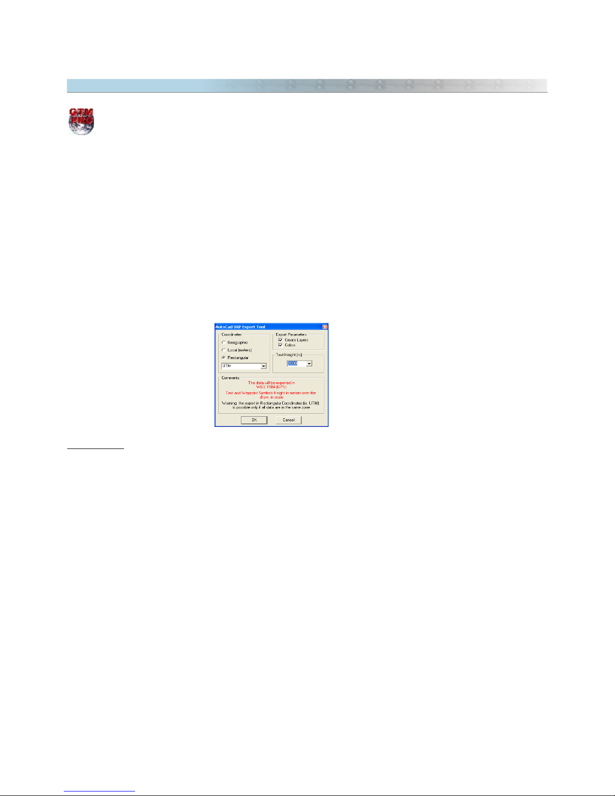
When exporting, the program will open a window with the following options:
Coordinates
Geographic:
Selecting this option, the data will be exported to geographic coordinates, in decimal format and
with twelve decimal places of accuracy.
Local
: This option is useful when the User wants to export the data to a unusual metric system of coordinates,
with origin (coordinates 0,0) defined in the lower left side of a rectangle bound to the data. This option will stay
enabled, even if the data is in different zones. Though, the User must be careful when using it in the export of
data that surpasses 6º of horizontal extension, because the errors in the edges can affect the data accuracy.
Rectangular :
Data Export in metric system, in rectangular coordinates, with two decimal places of accuracy.
This option will only be enabled if the data is in the same zone as one of the rectangular systems from GPS
TrackMaker® coordinates. The zone indication will be omitted when exporting. For further information about
rectangular coordinates systems, see Configuring Coordinates System.
19
Page 20

Export Parameters
Create Layers:
Whenever possible, this option should be selected to create five different layers that will facilitate
a better visualization in AutoCAD®. The Created layers will have the following names:
•
Comments:
Layer of Waypoint comments
•
Names:
Layer of the Waypoint names
•
Routes:
Layer of the Routes
•
Tracklogs:
Layer of the Tracklogs
•
Waypoints:
Layer of circles and indicative points of Waypoint icons
Colors:
Creates the export with the same colors indicated in GPS TrackMaker®. If this option is not selected,
the data will be exported in black or white color, depending on the background color defined in AutoCAD®.
Text Height
Choose the maximum height of the text and of the icon from exported Waypoints, avoiding confusion when the
Zoom
tool is used in AutoCAD® environment. The height is indicated in meters and it will be shown to scale, even
if the data is exported using geographic coordinates.
20
Page 21
2.10 Importing Shapefiles (ArcView®)
The import of Shapefile (SHP format) files is possible in GPS TrackMaker®. This format is used by Arc/View®
from ESRI™ and other GIS programs.
To import data in SHP format, choose
File > Open File > Arc/View Shapefiles
.
When importing, it is necessary to indicate the datum in which the data is saved. Through the Import Tool, you
can choose the rectangular coordinate system or the starting point for data saved in a metric grid.
Also configure the
Altitude
option to the correct unit. Feet or meters can be chosen.
Each SHP file has a database file in DBF format that can also be read by GPS TrackMaker®. When importing,
the
Import Tool
window will show a specific field for the DBF file, and you can choose which field of the DBF file
will be transferred for Tracklog names, and also, for the Waypoint names, and for the Waypoints comment.
The following shapes are supported:
• Point
• PolyLine
• Polygon
• PointZ
• MultiPoint
• PolyLineZ
• PolygonZ
21
Page 22
2.11 Exporting Shapefiles (ArcView®)
This option is available only in GPS TrackMaker Professional® .
To export data to the Shapefile format of ArcView® programs, choose
File > Save File as > Shapefile ArcView file
.
The export datum will be the current datum of the GPS TrackMaker®. The respective DBF and SHX files will also
be created with the SHP file.
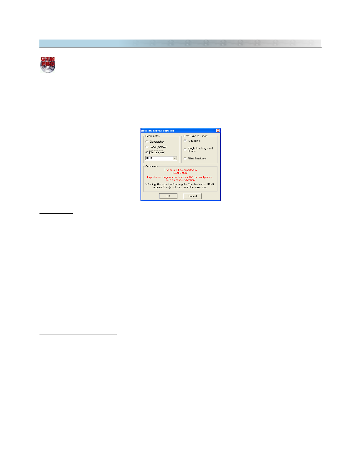
When exporting, the program will open a window with the following options:
Coordinates
Geographic:
Selecting this option, the data will be exported in geographic coordinates, in decimal format and
with twelve decimal places of accuracy.
Local
: This option is useful when the User wants to export the data to a unusual metric system of coordinates,
with origin (coordinates 0,0) defined in the lower left side of a rectangle bounded to the data. This option will stay
enabled, even if the data is in different zones. Though, the User must be careful when using it with data that
exceeds 6º of horizontal extension, because the errors in the edges can degrade data accuracy.
Rectangular:
Data exported in metric system, in rectangular coordinates, with two places of accuracy. This
option will only be enabled if the data is in the same zone as one of the rectangular systems of coordinates of GPS
TrackMaker®.
The zone indication will be omitted when exporting. For further information about rectangular systems of
coordinates, refer to Configuring the Coordinates System.
Type of data to be Exported
Waypoints
: will be exported as
Points
, with the registration of all Waypoint attributes
Simple Tracks and Routes
: will be exported as
Polylines
Filled Tracklogs
: will be exported as
Polygons
22
Page 23

2.12 Exporting XLS Files (MS Excel®)
This option is available only in GPS TrackMaker Professional® .
To export data to XLS (spreadsheets of Microsoft Excel®) format, choose
File > Save File as > Microsoft Excel 2.1
Table
.
The export datum will be the current datum of the GPS TrackMaker® program.
Waypoints, Tracklogs and Routes will be exported in three single XLS files.
The export is made in Microsoft Excel® 2.1 format that possesses a limitation of approximately 32700 lines in each
table.
Exported attributes:
Isolated Waypoints or in Routes
- Index number
- Name
- Coordinates with the current Notation of GPS TrackMaker®
- Altitude in meters or feet
- Date and hour with the current notation of the computer’s regional settings
- Comments
- Icon number according to the Icon Table
- Angle of rotation of Waypoint Text
- Waypoint’s display on the screen
0
– Symbol with name
1 –
Symbol only
2 –
Symbol with comments
3 –
Symbol with comments defined by User
Tracklogs
- Tracklog name
- Index number
- Coordinates with the current Notation of GPS TrackMaker®
- Altitude in meters or feet
- Date and hour with the current notation of the computer’s regional settings
Routes
- Route Name
- Waypoint’s attributes
23
Page 24

2.13 Exporting DBF Files (dBase®)
This option is available only in GPS TrackMaker Professional® .
To export data to DBF (dBase®) format, choose
File > Save File as > dBase IV Database
.
The export datum will be the current datum of the GPS TrackMaker®.
Three files will be created for Waypoints, Tracklogs and Routes respectively.
Exported attributes:
Isolated Waypoints or in Routes
- Index number
- Name
- Coordinates with the current Notation of GPS TrackMaker®
- Altitude in meters or feet
- Date and hour with the current notation of the computer’s regional settings
- Comments
- Icon number according to the Icon Table
- Angle of rotation of Waypoint Text
- Waypoint’s display on the screen
0
– Symbol with name
1 –
Symbol only
2 –
Symbol with comments
3 –
Symbol with comments defined by User
Tracklogs
- Tracklog name
- Index number
- Coordinates with the current Notation of GPS TrackMaker®
- Altitude in meters or feet
- Date and hour with the current notation of the computer’s regional settings
Routes
- Route Name
- Waypoint’s attributes
24
Page 25

2.14 Importing and Exporting Files in PCX5 Format
Importing Files in PCX5 Format
Files in GRM, TRK, WPT and RTE formats are recognized in the following notations:
• dd.ddddd
• dd mm ss.ssss
• dd mm.mmmm
• UTM.
• British Grid
• German GR
• Irish Grid
• Swiss
• Swedish R90
• Taiwan 67 Grid
To import, choose
Files > Open File >PCX5 Files
option to view files with PCX5 program extensions.
Note that in data import, the Waypoint text will be configured to capital letters. Use the
Convert Text to Lower
Case
tool to change the imported text to lowercase, for better readability on the screen. See topic: Converting
Waypoint Text to Lower case.
Saving Files in GRM Format from PXC5
GPS TrackMaker® allows you to save files in GRM (Garmin® PCX5) program format. GRM format saves
Tracklogs, Routes and Waypoints into the same file.
The data will be always saved in
dd.ddddd
notation and WGS 84 datum.
To save data in GRM format, just to choose Files > Save as > Garmin PCX5.
25
Page 26

2.15 Importing Files in E00 Format
File import in E00 format is possible in GPS TrackMaker®. The program Arc/INFO® uses this format.
In GPS TrackMaker® the import of E00 format can be done with data saved in geographic coordinates,
rectangular system supported by TrackMaker, or User's grid.
To do the import, when opening the file, choose the
Arc/INFO Export Files
option to view the files with the E00
extension.
When importing the data, indicate the datum for the data to be saved. Through the Import Tool, you can choose
the rectangular coordinate system or the starting point for data saved in a metric grid.
Note that for data in the E00 format, the text will be converted to uppercase. You can use Convert Text to Lower
case tool to change the imported text to lowercase, for better readability on the screen.
26
Page 27
2.16 Importing MIF/MID Files (MapInfo®)
The import of MIF/MID format can be done with data saved in geographic coordinates, rectangular coordinates or
in user's grid.
To import, when opening the file, just choose the
MapInfo Files
option to view files in MIF/MID extension.
GPS TrackMaker® recognizes most of the datum parameters automatically supported by MapInfo®, indicating
which is the most appropriate datum for the import. If the MIF/MID file is recorded in geographical coordinates,
the import will be direct.
However, for data saved in unknown rectangular systems, you must correctly indicate the datum in which the data
was saved. Through Import tool you can also choose the rectangular system of import or the origin point for data
saved in a specific metric grid.
When importing MIF/MID files, the following graphic elements are recognized:
- LINE, POLYLINE e MULTIPLE POLYLINE as simple Tracklogs
- REGION as filled Tracklogs
- POINT as Waypoints
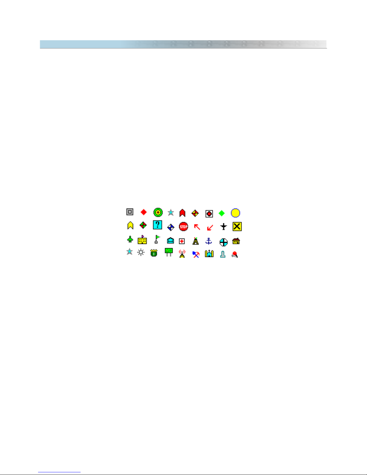
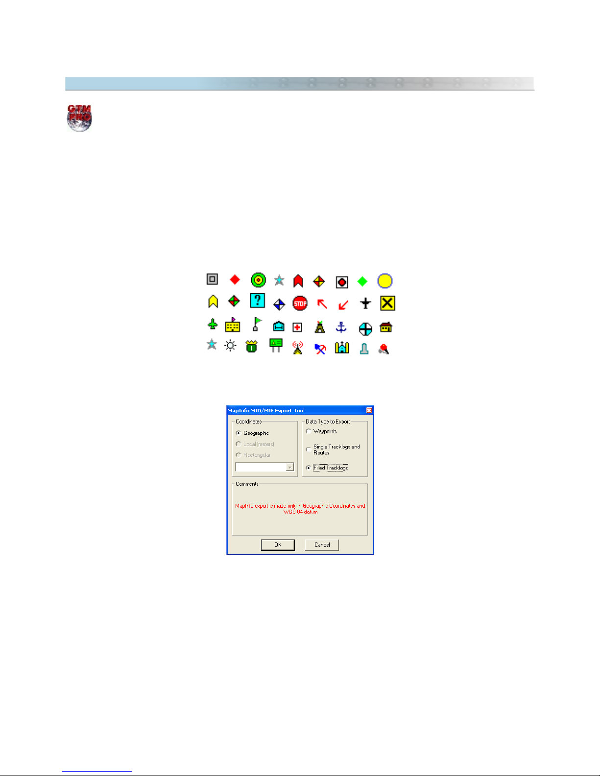
The imported icons are:
Each MIF file has a database file in MID format that can also be accepted by GPS TrackMaker®. When
importing, the Import tool window will show a specific field for the data from MID file, being possible to choose
which text field will be transferred to Tracklogs names, and also, to the names and Waypoint comments.
27
Page 28
2.17 Exporting MIF/MID Files of MapInfo®
This option is available only in GPS TrackMaker Professional®.
To export data in MIF/MID format of MapInfo®, click in
File > Save File as > MapInfo Files
GPS TrackMaker® exports to MIF/MID format using the following rules:
- Tracklogs and Routes are exported as
Polylines
- Filled Tracklogs are exported as
Region
- Waypoints are exported as Point with support for some icons
The exported icons are:
Exporting MapInfo® files, GPS TrackMaker® will open a window with the following options:
Coordinates
The data are always exported in geographical coordinates, using decimal format with twelve decimal places. The
export datum is always WGS 84.
Data type to Export
Waypoints, Routes, single Tracklogs and filled Tracklogs are exported in separated MIF/MID files.
28
Page 29
2.18 Files Saved in Multi Media Cards (MMC and SD)
Some GPS devices supports MultiMedia Cards (MMC) and Security Digital Media Cards (SD)
allowing to store a lot of Tracklogs, Routes and Waypoints. These cards need usually an
USB Media Reader/Writer to transfer the data to/from the computer.
GPS TrackMaker® can recognize files stored in MMC or SD of the following GPS devices:
Lowrance iFinder® and Similar Models
The iFinder® and similar models have the capacity to store more than 50000 trackpoints, 1000 waypoints and
1000 icons that can be recorded in a single file with the USR extension.
iFinder® is able to record several USR files in a single card (MMC or SD).
To open USR files, click in
Files > Open File > Lowrance MMC Files
.
To save USR files, click in
Files > Save file as > Lowrance MMC Files
.
Magellan Meridian®, Sportrak® and Similar Models
Meridian®, Sportrak® and Explorist® families can save Tracklogs, Routes and Waypoints directly in MultiMedia
Cards and Security Cards, saving in separate files. In some models, the files are saved without a defined
extension.
Waypoints and Routes can be saved in a single file.
Tracklogs can be saved in separate files, having each file, a single Tracklog. They also can be saved in a single file,
but the date information will be lost.
To open Magellan files saved in MMC and SD, click in
Files > Open File > Magellan MMC Files
.
To save Magellan files, click in Files > Save File as > Magellan MMC files.You must choose which data type will be
saved in Magellan format.
29
Page 30
2.19 Data Import Tool
In GPS TrackMaker®, file import can be done with data saved in geographic coordinates, saved in a rectangular
coordinate system supported by GPS TrackMaker® and saved in a local grid.
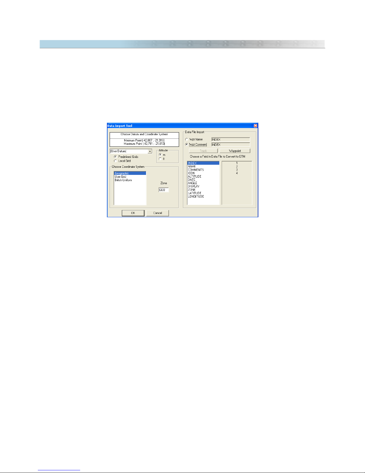
The import window will appear when the User opens the file to be imported.
Most of the imported files don't have the datum indication in which the data will be saved. So, you must correctly
indicate the datum and the zone, in cases of file import in rectangular grids such as UTM. See Datum Table to
learn which are the available datum systems in GPS TrackMaker®. Also see Configuring the Coordinate System.
The wrong indication of the datum doesn't harm the import. But differences of some dozens or hundreds of meters
between the real position of the data and the indication in GPS TrackMaker®'s screen can appear.
Importing data in Geographic Coordinates
Before the file import, GPS TrackMaker® analyzes the maximum and minimum limits of the data. If the values are
compatible with geographic coordinates, a window will be opened, asking for the choice of the datum in which the
data will be saved and the appropriate coordinate system. To import geographic coordinates, choose
Geographic
.
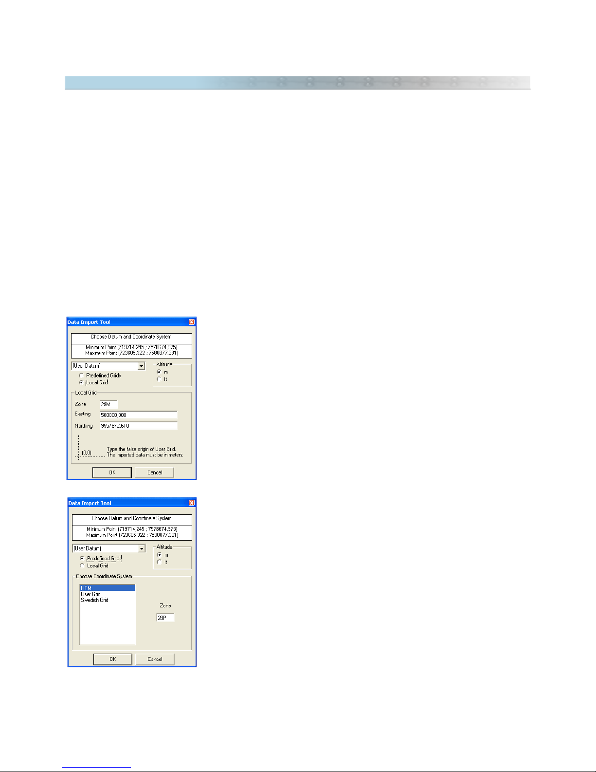
Importing data in a Specific Local Grid
If the
Local
option is selected, the data will be imported, adopting a specific
metric grid of an origin defined by the User.
So, avoid using data that has a horizontal width greater than 6º, because
deformations created by Meridian Convergence (Grid Declination) can appear.
Importing data saved in a Rectangular System
Before the file import, GPS TrackMaker® analyzes the maximum and minimum
limits of the data. If the values are compatible with some rectangular system
supported by TrackMaker, the window to the side will be opened, asking for the
datum in which the data will be saved, the zone and the indication of the
supposed rectangular coordinate system. Choose one of the rectangular systems
indicated in the list.
When importing files using rectangular grids, the wrong indication of the zone
will harm the import, leading the program to recognize the coordinates of each
point in an unusual way. In this case, the User must identify the data
irregularity, re-doing the import in the appropriate zone. The wrong indication of
the zone can displace the data hundreds or even thousands of kilometers off its
real position.
30
Page 31

2.20 Converting Blocks of Files
Sometimes it is necessary to convert all files saved in a directory to another file format. To avoid the use of “
Open
File
” and “
Save File as
” repeatedly, GPS TrackMaker® offers the option to convert blocks of files automatically. To
access it, click on
Files -> Convert Files
menu.
Origin Directory and File Format
Press to choose the origin directory and the file format to be converted.
Target Directory and File Format
Press to choose the target directory and file format.
File Conversion
After choosing the directories and the file formats, press to start the automatic process of conversion. The
names of the converted files will be shown on screen.
All files with the same extension located in the source directory will be converted to the destination format. Press
to stop the process.
Important: some files such as SHP, E00, MIF and others request some parameters of importation and
exportation when opened or saved. The process of conversion will open continually the windows of importation
and exportation for each file converted.
2.21 Automatic File Backup
The automatic backup increases the security against data loss caused by errors when editing or by problems in
your computer. To enable it, click in
Tools -> Options
and mark the option
Use Recycle Bin as backup area
.
Once enabled, whenever a file is replaced by a newer version, a copy of the old file will be sent to the Windows
Recycle Bin.
To restore the old file, open the Windows Recycle Bin, right-click on the file name and choose
Restore
. The
backup files are removed when the Recycle Bin is emptied.
31
Page 32

3 Waypoints
3.1 Creating, Editing and Deleting Waypoints
Waypoints are geodesic points stored in the GPS receiver’s memory and can be transferred to the PC using the
GPS TrackMaker® program. Usually they represent specific places, such as cities, squares, bridges, crossings, etc.
A Waypoint has the following components:
• Latitude
• Longitude
• Name up to 10 characters
• Comments up to 255 characters
• Rotation angle of the Waypoint Text
• Creation date
• Altitude of the Point
• Visualization in the screen
• Specific graphic symbol
After being transferred to the PC, all Waypoint data can be easily modified using the GPS TrackMaker® program.
To show or hide all Waypoints, click on the button or press <CTRL W>.
Creating a Waypoint
Creating a Waypoint in GPS TrackMaker® program is a
very simple task. Just press the
Pencil
tool or the
Route Creation Tool located on the drawing tool bar or
in the
Tools
menu and, using the left mouse button, click at
the point on the screen where you want to create a new
Waypoint.
A creation window will be displayed allowing to change the
geodesic coordinates of the point, the display scheme , the
icon, the name and comment and other fields.
To facilitate the creation of Waypoints with text rotation, select a Tracklog or Route
segment and then create the Waypoint, The angle of the text will be the same as
the Tracklog or Route. This feature facilitates the creation, for example, of urban
maps, where the name of each street or avenue has the inclination of the street or
avenue. In the example, Waypoints were created without icons.
32
Page 33

Each Waypoint has a screen visualization style that can be modified through the Waypoint Styles button. The
four basic styles defined in GPS TrackMaker® are:
Symbol with Name: The reduced name is shown in the screen together with the icon
Symbol Only: Only the icon is shown in the Screen
Symbol with Comments: The comment is shown in the screen together with the icon
Text box: Special visualization mode that shows comments on the screen in multiple lines. The icons and the text
rotation are not shown in this visualization mode.
Waypoint on Screen until...
In this field, the User can define the parameters of the scalable Waypoint.
The text box has a Predefined list of values to the scalable Waypoints:
Permanent:Text that always stays on the screen
Country: Used in the indication of names of large size countries
State Large: Names of large size states or medium size countries
State Medium: Names of medium size states or small size countries
City Large: Names of large metropolises
City Medium: Names of medium size cities
City Small: Names of small cities or villages
Urban Area: Indication of metropolitan areas
Neighborhood: Suburbs or small details on map
Highway: Value suggested for highways or for small details on maps
Avenue: Avenues and small details on maps
Street: Suggested value for very small details on maps
Creating a default Waypoint
If you need to use frequently a Waypoint with the same icon and text style, it is a good idea to create a
default
Waypoint.
Every time a Waypoint is created, the default style will be applied. To define a default Waypoint, choose
a icon and define the text style and the rotation angle and press
33
Page 34

Editing an existing Waypoint
To Edit a Waypoint is as easy as creating it. First, press
located on
Drawing Toolbar
. With the
Detect
Elements
button pressed, place the mouse pointer
over the Waypoint icon until a small circle appears around
the icon. Then click with the right mouse button until a
Waypoint Edit window is displayed. Do the necessary
changes and press OK.
Waypoint edition can be made easily through spreadsheets of GTM PRO®. See the topic Data Edition in
Table.
Deleting a Waypoint
To delete a Waypoint, first select it. For that, see Selecting Data.
Once the Waypoint is selected, press DEL to delete it from the memory.
34
Page 35

3.2 Editing Waypoint Styles
The Waypoint Style window can be opened through the Waypoints Editing window, by pressing the button . To
know more about the Waypoint Editing window, see the section Creating, Editing and Deleting Waypoints.
The Waypoint Style window has the following fields:
Visualization Area of Waypoint Text
This field displays how the Waypoint text will be shown in screen. The characteristics of the font used can be
changed through the <Edit Font> button. The background color of the text box is also displayed when this option
is chosen in the styles list.
Options for Text Box
The Options for Text Box are enabled only when the User chooses the Text Box option in the style list. Text box is
a special visualization mode that shows Waypoint comments in multiple lines on the screen. The icons and the text
rotation are not shown in this visualization mode, and only the first line is sent to GPS, because most receivers are
only capable of saving one line.
The
Opaque
option allows to apply a color background in the Text Box.
The <Color> button allows changing the background color of the Text Box.
The
Shadow
option allows to apply an 3D effect in the Text Box, with a shaded on background.
The
Border
option allows to define the thickness and the color of the border line of the Text Box.
35
Page 36

Predefined Styles List
The list of Predefined styles is similar to the available list in a Garmin® GPS, with additional Styles available in the
GPS TrackMaker®. To modify the characteristics of each style, click on the Style and modify the configurations
in the other fields.
Predefined styles are:
Symbol with Name: Shows the icon with the Waypoint name
Only Symbol: Shows only the icon
Symbol with Comments: Shows the icon with the Waypoint comment
Text Box: Shows the comments in a Text Box without the icon
<Edit Font> Button
Press this button to modify the font characteristics from the selected style in the styles list. Font name, size, color,
boldface, italics, underline, etc can be modified.
36
Page 37

3.3 Selection of Waypoints Through Icons
To select Waypoints through icons, press the button located on the Tool Bar. A window indicating only the icons
used in the file will appear. Just click on one of the icons and the program will select all the Waypoints that have
that same icon.
3.4 Modifying Several Waypoints at the Same Time
To change the icon and the view mode of several Waypoints at the same time, first select the desired Waypoints
through selection tools already described in Selecting Data.
With Waypoints selected, press the button on the Tool Bar, and choose a new icon or a new visualization
mode. Press <OK> and all selected Waypoints will have that chosen icon or chosen view mode.
The available view modes are:
• Symbol with Name : shows the icon with Waypoint name
• Symbol by Itself: it shows only the icon
• Symbol with Comment : it shows the icon with Waypoint comment
• Text Box: it shows the icon with Waypoint comment in special text
configured in
Options
in
Tools
menu
37
Page 38

3.5 Treating Repeated Waypoints
Frequently, after many downloads from the GPS or after merging files, the program stores a lot of repeated
Waypoints, harming the data manipulation.
To eliminate repeated Waypoints or to modify them, press the button on the Tool Bar or select the
Repeated
Wpts Tool
option in the
Tools
menu.
Selecting Waypoints with Repeated Names
With this option enabled, all Waypoints with the same name will be selected.
Selecting Close Waypoints
This option will select all the repeated or close Waypoints, allowing the User to verify which Waypoints are in a
same point or very close.
The User can define the maximum distance in meters or yards between two Waypoints so that the correct
Waypoints are selected. Sometimes repeated Waypoints are close, but have minor variation in their coordinates.
Choosing the distance, the User can define a maximum selection area. This way, any Waypoint that is in this range
will be selected, without depending on having the same icon, name or comment.
Modifying Repeated Names of Waypoints
Several GPS models don’t accept repeated names for Waypoints. Choosing this option, the program will modify all
the repeated names of Waypoints, creating an index number in the end of each repeated Waypoint, as follows:
WAYPON, WAYPO1, WAYPO2...
The index number will be inserted respecting the maximum size of 6 or 10 characters of the Waypoint name.
Creating Names of Waypoints from the Comments
This option creates names for Waypoints, from its written comments. Several GPS models don't have the field
Waypoint Comment
, having only the field
Waypoint Name
. For these models, the name must contain a clear
indication of Waypoint, so that it is possible to uniquely identify it without the need of the
Waypoint Comment
field.
38
Page 39

The examples below indicate how GPS TrackMaker® creates names from the Waypoints comments:
• New York Downtown (NYDOWN (6 characters) / NYDOWNTOWN (10 characters)
• San Jean Pied Port (SJPPOR (6 characters) / SJPPORT (10 characters)
• San Pedro de Atacama (SPATAC(6 characters) / SPATACAMA (10 characters)
• Sao Sebastiao de Aguas Claras (SSACLA (6 characters) / SSACLARAS (10 characters)
Creating Indexed Names of Waypoints
This option creates an indexed list of names for the Waypoints. It is necessary to choose the initial name.
Example: for
WAY
, the names will be
WAY1, WAY2,WAY3…
Convert Text to Lowercase: Selecting this option causes the text of all Waypoint comments in the computers
memory will be converted to lowercase with its first letter in uppercase, for better readability on the screen.
Convert Text to Uppercase: In the same way, the text of names and comments of all Waypoints can be
converted to uppercase.
3.6 Converting Waypoint Text to Lowercase
To convert Waypoints text to lowercase with first letter in capital, press the button on the Tool Bar and
select the
Convert Text to Lowercase
option, and then press the OK button.
The comment texts of all Waypoints in the memory of the computer will be converted to lowercase with its first
letter in uppercase, for better readability on the screen.
In GPS TrackMaker Professional®, click on
Tools -> Waypoints -> Convert Txt to -> Lowercase.
39
Page 40

4 Tracklogs
4.1 Creating, Editing and Deleting Tracklogs
Tracklogs are sequences of specific geodesic points stored in the memory of a GPS receiver and can be transferred
to the PC using the GPS TrackMaker® program. Usually they represent trails done with the GPS, such as
highways, avenues, streets, hiking trails, fences, walls, etc. It’s like leaving a trail of breadcrumbs as you’re
traveling. A Tracklog can be represented by one or more straight segments, ending in points called
Tracklog
Points
They are composed of:
• Latitude
• Longitude
• Date and time when the Tracklog was registered by the GPS receiver
• Altitude in relation to the sea-level
After being transferred to the PC, all Tracklog data can be modified using the GPS TrackMaker® program.
Tracklogs are represented by continuous segments of straight lines with colors and styles defined by User.
To show or hide Tracklogs, click on the button or press <CTRL T>.
Creating a Tracklog
To create a Tracklog in GPS TrackMaker® program is a very simple task. Just press the
Pencil
tool located on
toolbar or in the
Tools
menu, and with the left mouse button, click and hold on the point of the screen where
you want to begin the Tracklog and drag it to the point where you want to mark the end of the track. Then release
the mouse button. Date is not implemented on the Tracklog records, because it could cause mistakes, indicating
wrong speeds on the segment.
You can also use the Drawing Tools to create Tracklogs in many forms.
Tracklogs can be created through spreadsheets of GTM PRO®. See the topic Data Edition in Table.
Editing a Tracklog
To edit Tracklogs, press
Detect Elements
Button and Selection Tool Click on a Tracklog segment
and wait until it’s color changes. Then, press the right mouse button so the editing window will appear.
40
Page 41

In this window, the following data related to the track can be changed:
• Geodesic coordinates (latitude/longitude) of the segment points
To change the coordinates, verify the Coordinate System, defined under
Options
, in the
Tools
menu.
• Length of the segment
Changing the length causes the change of the geodesic coordinates of the second point of the Tracklog
segment, which is done automatically by the program. Verify the Length Unit of Measurement defined under
Options
in the
Tools
menu.
• Azimuth of the segment (Bearing)
The azimuth must be between 0º and 360º (as shown). The reference will be the true axis NorthSouth when the program is configured for geographic coordinates (Azimuth/North). In rectangular
systems such as UTM systems, if the segment is contained in only one zone, the reference will be the
north-south axis of the grid (Azimuth/Grid). A change of the angle will necessarily imply the
modification of the geodesic coordinates of the second point of the segment
To change the notation of the azimuth, see Configuring Azimuth Angle.
• Tracklog Name
Each Tracklog can have a name for identification or a small text that individualizes it. This name or text can be
searched through dialog box
Tracks and Routes
located in Tool Bar 2.
41
Page 42

• Tracklog Style
The User can choose one of several available styles. For convenience, the program provides a defined list with
suggestions of several styles, as indicated below:
• Blue Major Highway
• Red Major Highway
• Principal Road
• Arterial Road
• Principal Street
• Paved Street
• All Weather Unpaved Road (unpaved road in good conditions)
• 4WD Trail (precarious unpaved road)
• Hiking/Bike Trail
• River/Canal
• Big River
• Intermittent River
• Railway
• Freight Railway
• Tourist Railway
• Forest Boundary
• Ferry Boat Line
• Contour Line (Main)
• Contour Line (Secondary)
• Contour Line (Detail)
• Depth Contour Line (Main)
• Depth Contour Line (Secondary)
• Depth Contour Line (Detail)
• County Boundary
• Interstate Boundary
• International Boundary
• Green Map Border
The Filled Predefined Tracklogs are:
• Hidrography I
• Hidrography II
• Earth Surfaces
• Wetland
• Metropolitan Area
• Building Area
• Military Area
• Airport Area
• Cemetery Area
• National/State Park
• Urban Area
• Desert Area
• Swamp Area
• Glacier Area
• Mountainous Area
• Yellow Map Background
42
Page 43

• Tracklog Color
The Tracklog color can be modified, through the
Tracklog Color
Button.
• Tracklog Style Default
To apply the style default, press the
Default
button.
• Defining a Tracklog as default
Press the button to define the selected Tracklog as default. This default will be used each time the
Default
button is pressed.
• Sending Tracklog to back
With the button pressed, the edited Tracklog will be totally sent to the back of the other Tracklogs.
However, the change will be made only after pressing OK button.
• Bringing Tracklog to front
With the button pressed, the edited Tracklog will be totally sent to the front of the other Tracklogs. The
change will be made only after pressing OK button.
• Scale - Scalable Tracklogs
You can set the level of zoom for which the selected Tracklog remains displayed. When the set value is exceeded,
the Tracklog will no longer show but will still exist.
Text Box has a predefined list of values for scalable Tracklogs:
Permanent: Tracklog always stays on screen
Country: Used to designate boundaries of large size countries
State Large: Designates large size states or medium size countries
State Medium: boundaries of medium size states or small size countries
City Large: boundaries of large metropolises
City Medium: boundaries of medium size cities
City Small: boundaries of small cities or villages
Urban Area: boundaries of metropolitan areas
Neighborhood: Suburbs or small details in map
Highway: Value suggested for highways or for small details in maps
Avenue: Avenues and small details in maps
Street: Suggested value for very small details in maps
43
Page 44

You can view the following data in the edit window:
• Date in which the Tracklog was recorded by the GPS receiver (Date)
• Tracklog number (Track #)
• Tracklog segment number (Segment #)
• Time spent (in days, hours, minutes and seconds) on the accomplishment of the Tracklog (Time Interval)
Complete Tracklog edition can be made easily through spreadsheets of GTM PRO®. See the topic Data
Edition in Table.
Deleting a Tracklog
To delete a Tracklog or one of its segments, first select it. For that, refer to Selecting Data
Once the Tracklog or segment is selected, just press DEL to remove it from memory.
Uniting Tracklogs
Tracklogs can be united easily with the Drawing Tools. Visit the topic Uniting Tracklogs and Routes with the
Drawing Tools.
44
Page 45

4.2 Selecting Tracklogs by Style
This function is useful when used with the Editing Several Tracklogs at the same time.
To select Tracklogs by style, press the button in the Toolbar. A window will appear asking which style and
color of Tracklogs will be selected. After choosing one of the styles and its color, press the <OK > button. The
program will select all Tracklogs with that same style.
To aid in the procedure, select a Tracklog (see Selecting Data) before pressing the button . If done, the style
of the selected Tracklog will be automatically shown in the Selecting Tracklogs by Styles window.
Don’t forget that to show Tracklogs by styles, the button located in the Tool Bar must be released;
otherwise, Tracklogs will be shown in different colors.
45
Page 46

4.3 Editing Several Tracklogs at the Same Time
To change the color, style and name of several Tracklogs at the same time, select the desired Tracklogs through
the selection tools already described in Selecting Data. Then press the button on the Tool Bar.
The Tracklog style editing window will appear with the following options:
Tracklog Name
Each Tracklog can have a name for identification or a small amount of text
that individualizes it. This name or text later can be searched through the
Tracklogs and Routes
box on the Tool Bar.
Tracklog Style
You can opt for one of the several available styles. To facilitate the choice,
the program gives a defined list with suggestions of several styles, as
indicated below:
• Blue Major Highway
• Red Major Highway
• Principal Road
• Arterial Road
• Principal Street
• Paved Street
• All Weather Unpaved Road (unpaved road in good conditions)
• 4WD Trail (precarious unpaved road)
• Hiking/Bike Trail
• River/Canal
• Big River
• Intermittent River
• Railway
• Freight Railway
• Tourist Railway
• Forest Boundary
• Ferry Boat Line
• Contour Line (Main)
• Contour Line (Secundary)
• Contour Line (Detail)
• Depth Contour Line (Main)
• Depth Contour Line (Secundary)
• Depth Contour Line (Detail)
• County Boundary
• Interstate Boundary
• International Boundary
• Green Map Border
46
Page 47

The Filled Predefined Tracklogs are:
• Hidrography I
• Hidrography II
• Earth Surfaces
• Wetland
• Metropolitan Area
• Building Area
• Military Area
• Airport Area
• Cemetery Area
• National/State Park
• Urban Area
• Desert Area
• Swamp Area
• Glacier Area
• Mountainous Area
• Yellow Map Background
Tracklog Color
The Tracklog color can be modified, through the
<Tracklog Color
> button.
Scalable Tracklogs
The parameters of the Tracklog scale can be defined through the scale box. The scalable Tracklog stays on screen
until the defined scale is exceeded. Then the Tracklog will be hidden. For further information, see Scalable
Tracklogs.
Default style of the Tracklog
To apply the default style, just press the button with the image of the Tracklog Default.
Defining a Tracklog as Default
To define the chosen Tracklog as default, press the button. This pattern will be used every time that the
program creates a new Tracklog or imports it from a file that is not standard GTM.
TIP: to show Tracklogs by style, the button located on the Tool Bar must be released, otherwise,
Tracklogs will be shown in different colors.
47
Page 48

4.4 Reducing Tracklog Size
Tracklog Reducer
function, accessed through the button allows you to reduce the size of a Track, reducing
track point’s number in accordance with the reduction level chosen by the User, letting you transfer a more
compact Tracklog to the GPS, that occupies less memory.
It is obvious that any reduction of a Tracklog can cause loss of precision, however, you must estimate if that loss
will harm the navigation. Most of the time that won't happen.
The
Tracklog Reducer
function won't delete the old Track, allowing you to compare and to estimate if the
reduction is adequate.
To access the reduction Tracklog window, first it is necessary to select one or several Tracklog segments using one
of the selection tools indicated in Selecting Data. Then, press the button in Tool Bar or choose
Tracklog
Reducer
option in
Tools
menu.
The reduction window will open with the following options:
• Reduction Levels: 0 - maximum level ▪ 10 - minimum level
• Resolution: This option allows the maximum reduction possible, best for large Tracklogs with several
Trackpoints. The program verifies if Trackpoints are aligned into the same horizontal plane, reducing the
several segments of lines that present little pronounced deflection to just two points.
• Distance Interval: Basically in this option, the program establishes a maximum fixed distance defined by the
reduction level and it divides the Tracklog, establishing distance intervals relatively fixed. It is a reduction
technique that presents a larger amount of Trackpoints in relation to the
Resolution
system, allowing for a
better precision.
• Create a Route: In this option, the program creates a Route following the Tracklog, having as many Route
points as are established by the User. This option is especially useful when the User doesn't need a lot of
precision in Tracklog indication, setting the whole memory of the GPS free so new Tracklogs can be stored.
• Cut Tracklog if exceeds: this option limits the maximum number of vertexes, dividing the Tracklog in
smaller parts with maximum number of vertexes specified in the text box. This option doesn't affect the details
and the precision of the Tracklog.
• Selects Old Tracklog on Exit: Enabling this option, the program will select the old Track on exit, allowing
you to delete the Tracklog when exiting from the Tracklog Reducer window.
48
Page 49

The illustration on the side shows the differences between the
Resolution
method and the
Distance Interval
method. The
Resolution
method just considered 3 points for the reduction
while the
Distance Interval
method considered 7 points. The Tracklog was reduced to 14% of
the original size in the first method and to 32% in the second method.
Before doing the reduction, press the
Preview
button and it will show a report indicating the number of selected
Tracklogs, the total number of Trackpoints of the selected Tracklogs, the total of Trackpoints after reduction, and
the reduction rate as a percentage.
The reduction will only happen if the <OK> button is pressed.
4.5 Showing Tracklogs by Colors
To show Tracklogs in different colors, instead of styles, just press the button
The advantage of this view mode is to distinguish the several segment groups of each Track. The screen will also
refresh faster in this mode than in the tracklogs by styles view mode.
4.6 Tracklog Union Tool
In GTM PRO® you can use the
Tracklog Union
tool to combine different Tracklogs that have common
extremities. Just select the Tracklogs that you want to combine and then press the <CTRL U> or the
button
The
Tracklogs Union
tool is very useful when you want to have just one Tracklog
for filling purposes. The illustration to the side is an example of some Tracklogs
with common extremities before and after the use of the Tracklogs Union tool.
Notice that after the union, only one Tracklog remains created from the union of
the other Tracklogs.
To facilitate the visualization of several different Tracklogs that have common extremities, it is advisable to keep
the button pressed.
Configuring the
Tracklog Union
Tool
Clicking on the arrow beside the button , the following options are accessed:
•
Distance of Union
: choose the maximum distance that the extremities are united. Zero indicates that
the extremities only will be united if the points are coincident.
Unite Tracklogs:
•
With Same name :
Only Tracklogs with same name are united.
•
With same Style :
Only Tracklogs with same style are united.
•
With same Color :
Only Tracklogs with same color are united.
If two or more options are selected, the union is made only if all conditions are true.
TIP: for further information about Tracklog/Route union, see Uniting Tracklogs and Routes with the Drawing
Tools.
49
Page 50

4.7 Uniting Tracklogs and Routes with the Drawing Tools
Different Tracklogs can be united with the following Vector Drawing Tools.
Pencil Tool
Handfree Drawing Tool
Line Drawing Tool
To unite Tracklogs, press the
Detect Elements
button and one of the tools listed above. Place the mouse
arrow on the extremity of a Tracklog, press the left button and drag the mouse to the other extremity of Tracklog.
To conclude the union, release the left button if you are using the pencil tool or click again for the other tools.
To unite Routes, press the
Detect Elements
button and the Route Creation Tool button . Place the mouse
arrow on the extremity of a Route, press the left button and drag the mouse to the other extremity of Route. To
conclude the union, release the left button.
If you wish to open a window to confirm the union, see the topic Configuring the Behavior of the Program.
Note: Tracklogs and Routes cannot be united.
50
Page 51

4.8 Selecting Repeated Tracklogs
Frequently, after several downloads from GPS or after the use of
Merge File
, the memory is filled with a lot of
repeated Tracklogs, harming the data manipulation.
To select repeated Tracklogs to delete or edit them, press or click in Tools> Tracklogs/Rotes >
Select Repeated
Tracklogs
.
Select Repeated Tracklogs/Routes
This option allows a fast search of repeated Tracklogs and Routes,
considering only some basic information as number of points, initials
and final coordinates, similar length, etc.
Select Repeated Segments of Tracklogs/Routes
Option for complete comparison of repeated Tracklogs/Routes, allowing to select repeated segments of Tracklogs
and Routes. Information about distance and length of each segment are considered, leaving the comparison
process slow.
Configuring the Maximum Distance of Comparison
The verification of repeated Tracklogs/Routes is made with a defined tolerance in meters or yards. Larger the
value, more Tracklogs/Routes can be selected.
Zero or
Exact
defines the selection of repeated Tracklogs/Routes located exactly in the same position, without any
degree of tolerance.
Aborting the Process
Press ESC Key to abort the verification process.
4.9 Scalable Tracklogs
It is possible to set the distance level for which the selected Tracklog remains displayed. When the set value is
exceeded, the Tracklog will no longer show but will still exist. The Text Box has a predefined list of values for
scalable Tracklogs. They are only examples, and the User must adapt to his needs.
Permanent: Tracklog that always stays in the screen
Country: Used in the indication of boundaries of large size countries
State Large: Boundaries of large size states or medium size countries
State Medium: Boundaries of medium size states or small size countries
City Large: Boundaries of big size metropolises
City Medium: Boundaries of medium size cities
City Small: Boundaries of small cities or villages
Urban Area: Boundaries of metropolitan areas
Neighborhood: Suburbs or small details in map
Highway: Value suggested for highways or for small details in maps
Avenue: Avenues and small details in maps
Street: Suggested value for very small details in maps
51
Page 52

4.10 Fragment Tracklog Tool
Fragment Tracklog Tool is used to divide Tracklog that cut other Tracklogs, allowing the edition and deletion of
part of segments. In the intersection points of the Tracklogs, new points are created, fragmenting the segment in
two or more parts.
The side picture shows the intersection of two Tracklogs before
and after the Fragmentation. Note that after fragmenting, the
segment was divided in two parts, creating an extra point
exactly in the intersection.
To use the Fragment Tracklog Tool, first select the Tracklogs
and click in
Tools > Tracklogs/Routes > Fragment Tracklog
menu or click in . After using fragment tool, only
the fragmented Tracklogs will remain selected.
4.11 Applying Altitudes in Contour Lines
This option is available only in GPS TrackMaker Professional®.
Contour lines are imaginary lines that represents the same altitude on the terrain. Using GPS TrackMaker®, it is
possible to create Tracklogs with the same altitude to represent the Contour Lines of the terrain. For that, it is
necessary to apply a same altitude in the whole Tracklogs.
To create a Contour Line, select the Tracklog which will be applied the altitude and click in Tools >
Tracklogs/Routes > Apply Altitudes in Contour Lines or click in . Then type the altitude and press <OK>.
Also see Creating Altitude Profile Starting From Contour Lines
52
Page 53

4.12 Creating Altitude Profile Starting From Contour Lines
This option is available only in GPS TrackMaker Professional®.
Contour lines are imaginary lines that represent the same altitude on the terrain. The altitude is the vertical
distance above the mean sea level.
GTM PRO® allows the creation of altitude profiles starting from contour lines represented by Tracklogs. To create
the altitude profile from a group of contour lines, create a Tracklog with the
Pencil
tool , with just one
segment crossing the contour lines. Then, select the created Tracklog and click in or in
Tools >
Tracklogs/Routes > Create Tracklog of Altitude Profile
.
The Tracklog will be fragmented in the intersection points of the contour lines, registering the altitudes of each
contour line. The Altitude Profile window will be opened, showing the altitudes of the Tracklog.
Also, see Applying Altitudes in Contour Lines
53
Page 54

4.13 Vector Drawing Tools
Pencil Tool
- draws isolated segments of Tracklogs and creates Waypoints.
To create a segment of Tracklog, press the left button and drag the mouse to the new position. Release the left
button to create the segment. For further information, see Creating, Editing and Deleting Tracklogs.
To create a Waypoint, see Creating, Editing and Deleting Waypoints.
Route Creation Tool
- draws isolated segments of Routes and creates Waypoints.
To create a Route segment, place the mouse arrow on a Waypoint or on the extremity of a Route, press the left
button and drag the mouse to other Waypoint or other extremity of Route. Release the left button to create the
Route segment.
A Route can be created only if in its extremities there is another Route or a Waypoint. See the topic Creating,
Editing and Deleting Routes.
To create a Waypoint, see Creating, Editing and Deleting Waypoints.
Handfree Drawing Tool
- draws freely Tracklogs with multiple points.
Press the left button of the mouse and draw freely the Tracklog, maintaining the left button pressed. To conclude
the Tracklog, release the left button. The number of points will be shown in the status bar at the bottom of the
screen.
Line Drawing Tool
- draws Tracklogs with multiple points with segments of lines.
Click on time with left button at the beginning point and drag the mouse to the new position. It is not necessary to
drag the mouse with the left button pressed.
Each click with the left button creates a new vertex of the Tracklog.
To conclude the Tracklog, click with the
right
button of the mouse.
54
Page 55

Shape Drawing Tool
Shape Drawing Tools allow to create Tracklogs with predefined forms. The drawing is made in two stages:
1 – Press the left button and drag the mouse to the new position, maintaining the left button pressed. To conclude
the drawing, release the left button.
2 – Moving the mouse, the drawing will be rotated. Clicking with the left button of the mouse, the drawing will be
concluded with e chosen angle. Clicking with the right button, the drawing will be concluded without rotation.
TIP: to draw regular forms, drag the mouse with the <SHIFT> key pressed.
The available Shape Drawing Tools are:
Rectangle
Rounded Rectangle
Elipse
Triangle
Pentagon
Hexagon
Octagon
Open Window When Creating a New Tracklog
The button opens the window of Tracklog Edition when the first Tracklog segment is created, allowing to
change the Tracklog name and other attributes. This resource is useful when creating urban maps, allowing to
type names of streets and avenues in the moment they are created.
55
Page 56

4.14 Tracklog Labeling
Automatic Tracklog Labeling allows to view the name of the Tracklogs on screen, avoiding name overlaps. This
function is useful to view urban maps, showing streets and avenues with their names automatically. Usually the
name is shown beside the largest Tracklog segment.
To enable the Tracklog labeling, click in button and choose
Tracklog Labeling
option.
Eventually, if a name does not appear, use the button to zoom in the Tracklog.
To configure the size and color of the label text, click in
Tools > Options > General > Track Labels
. The
characteristics of the label text are saved in GTM files.
Note: The names of Routes will be shown the same way of the Tracklogs.
56
Page 57

5 Routes
5.1 Creating, Editing and Deleting Routes
Routes are sequences of Waypoints stored in the memory of a GPS receiver as straight segments and they can be
transferred to the PC using the GPS TrackMaker® program. Usually they represent the Route to be traveled by
the User. Using Routes, the GPS defines a whole navigation system, indicating which direction the User must take.
A Route has the following structure:
• Route name
• Route number
• Sequence of the Waypoints of the Route
The GPS TrackMaker® program treats Routes in many aspects the same way as it treats Tracklogs. However,
there are some basic differences that must be noted. After transfer to the PC, GPS TrackMaker® can modify most
of the Route data. Dashed segments (in 10 possible colors) represent the Routes.
To hide or to show Routes, click on the button or press <CTRL R>.
Creating a Route
A Route can be created only if in its extremities there is another Route or a Waypoint; if not, a Tracklog will be
created. A Route is more complex than a Track, as it contains all Waypoint information for each extremity, as well
as the Route name.
Creating or editing a route in GPS TrackMaker® is very similar to creating a Tracklog. The program shows
Routes on the screen, independently of showing the Waypoints of its extremities. Actually, the Waypoints from
Routes are stored independently of other Waypoints on the screen. So, if you want to edit a Waypoint from a
Route, you must edit the Route itself, modifying the internal Waypoints.
Important: the Waypoints of Routes are always internal and independent from other Waypoints.
To create a Route, press located on Drawing Toolbar. Click with the left mouse button on a Waypoint or on
the extremity of another Route and drag the mouse to the next Waypoint or Route extremity. The Routes are
shown with dashed segments.
Routes can be created through spreadsheets of GTM PRO®. See the topic Data Edition in Table.
57
Page 58

Editing a Route
Route editing is done only on isolated segments. Press
Detect Elements
button and Selection Tool and move
mouse pointer close to a Route segment and wait until its color changes. Then, press the right mouse
button so the editing window will appear.
In this window, the following data related to the Route can be changed:
• Length of the segment
Changing the length causes the change of the geodesic coordinates of the second point of the segment, which is
done automatically by the program. Verify the Length Unit of Measurement defined under
Options
in the
Tools
menu
• Azimuth of the segment (Bearing)
The azimuth can be defined by the User and must be between 0º and 360º (as shown). The
reference will be the true axis North-South when the program is configured for geographic
coordinates (Azimuth/North). In rectangular systems such as UTM systems, if the segment is
contained in only one zone, the reference will be the North-South axis of the grid (Azimuth/Grid). A
change of the angle will necessarily imply the modification of the geodesic coordinates of the second
point of the segment.
To change the notation of the azimuth, see Configuring Azimuth Angle.
Route name
Each Route has a name to identify it. When a new Route is created, the program automatically creates a name like
Route #1, #2, #3..
. The Route name can be changed, observing the maximum of 30 characters.
58
Page 59

Features of the Route Waypoints
Each Route segment has a Waypoint in its extremities. To modify these Waypoints, just press the buttons <W> of
the vertexes #1 and #2 of the Route segment. Editing is done inside of the Waypoint editing window, described in
the section Creating, Modifying and Deleting Waypoints. To modify the geodesic coordinates of every Route
Waypoint, be aware of the coordinate system, defined under
Options
in the
Tools
Menu.
The following data in the edit window can be viewed:
• Name of each Waypoint of the Route
• Comments for each Waypoint in the Route
• Route number (Route #)
• Route segment number (Segment #)
Speed and time indications are not available for the Routes. Remember that only the Tracklogs have this data.
Routes can be easily edited through spreadsheets of GTM PRO®. See the topic Data Edition in Table.
Deleting a Route
To delete a Route or a segment, first select it. For that, please refer to Selecting Data
Once the Route or part of it is selected, just press DEL to remove it from memory.
Uniting Routes
It’s possible to easily unite Routes with the Route Creation Tool. Press and click with left button on the
extremity of the Route, dragging the mouse to another extremity of other Route.
59
Page 60

5.2 Selecting Waypoints far from Routes
This function is available in
Tools
menu and allows removing all Waypoints located away from the Routes. So the
GPS can be loaded only with the most interesting Waypoints closest to the Route.
Many GPS receivers have a limited memory for Waypoints. This function allows loading the receiver with
Waypoints located at a chosen distance to the Routes up to 200 km or 125 Miles. The advantage is that the User
can schedule a trip, loading only interesting locations into the receiver.
After loading the file, just draw the Routes that you want between the
Waypoints and call the
Select Wpts far from Routes
in the
Tools
menu. Then
choose the maximum distance of the Route within which the Waypoints won’t
be selected.
Press <MARK> button so the number of selected and non-selected Waypoints will be indicated. Note that the
selected Waypoints can be removed using the DEL key or through the {bmc bt_delete.bmp} button in Toolbar.
The non-selected Waypoints will remain on screen and can be transferred to the receiver using the respective
Interface
. Observe the maximum distance chosen: as larger the distance, more Waypoints will remain non-
selected.
If
Mark wpts out of quadrant
box is enabled, only the Waypoints located outside of the Route quadrant will be
selected.
In GTM PRO®, press to select Waypoints far from Routes.
60
Page 61

6 Maps
6.1 Overview
Vectorial Maps of Background are available in GPS TrackMaker® #13 and GTM PRO #4.0 or above. Basically they
are maps that open very very fast on screen, facilitating the location of Waypoints, Tracklogs and Routes.
Because they open very fast on screen, the maps are also useful in real-time navigation if compared with raster
images. Raster images demand a great amount of memory and are slower to load.
The Vectorial Maps of Background have the following characteristics:
- Open very fast on screen.
- The maps are automatically loaded when the program is opened.
- The maps consume very less memory if compared with raster images.
- The maps are totally independent and don't use reserved memory for Tracklogs, Routes and Waypoints.
- Allow the detection of elements with the mouse pointer.
- Non-editable maps. Once created, they cannot be modified.
- Have the extension MAP for maps and PJC for Project of Maps.
- The maps are loaded on demand. Only the maps shown on screen are loaded on memory.
- Automatic labeling. Names of streets, avenues, buildings, rivers, lakes and other elements are automatically
shown.
- Support for graphical accents and special characters.
- Allow fast text search.
- Support for all styles of Tracklogs with 16 millions of colors.
- Support for all Waypoint icons available in GPS TrackMaker®.
- Allow rotation of Waypoint text.
- Support for scalable Waypoints and Tracklogs.
- The trackpoints are limited in 4000 points.
- Complete support for
True Grid
mode. Once created, the MAP file is automatically shown in any coordinate
system and datum supported by GPS TrackMaker®.
- The MAP files are encrypted and allow restrictions by password or hardware key.
- The maps can be shown in gray scale to avoid confusion with Tracklogs, Routes and Waypoints.
- Multiples projects of maps can be registered.
- GPS TrackMaker® is able to create MAP files.
– GTM PRO® is able to create MAP files and complete projects of maps with extension PJC
Visit www.trackmaker.com to get free projects of maps for GPS TrackMaker®.
61
Page 62

6.2 Accuracy of MAP Files
A small price is paid when using MAP files. Unlike GTM files that allow full edition and register the coordinates with
13 decimal places, the MAP files may present small errors of accuracy that depends how the file was created.
For Waypoints, the maximum error is 10 inches (25 cm) close to the Line of Ecuador.
For Tracklogs, the error depends on the maximum size of the largest segment. See the table below:
Maximum Size of the Largest Segment Maximum Error
8,958 yards 10 inches
17,917 yards 20 inches
26,875 yards 30 inches
35,834 yards 40 inches
... ...
2,284,513 yards 69.72 yards
Above 2,284,513 yards 1328 yards
The maximum error may occur in equatorial region. As closer as Earth’s poles, smaller will be the error.
To minimize the error in Tracklogs, avoid to create big segments together with small segments. Big segments
increase the error in the small segments.
The polygon 1 in the picture below must be avoided. To get a best result, transform it to the polygon 2 that is
more homogeneous.
Another way to eliminate big segments united to small segments is to use the toll called Homogenize Points of
Tracklogs located in
Tools -> Tracklogs and Routes.
Finally, remember that all information above applies only to MAP files and not to GTM files.
62
Page 63

6.3 Homogenizing Points of Tracklogs
A small price is paid when using MAP files. Unlike GTM files that allow full edition and register the coordinates with
13 decimal places, the MAP files may present small errors of accuracy that depends how the file was created.
For further information, see Accuracy of MAP Files.
MAP files created with Tracklogs that have big segments united to small segments may present small errors in
polygon such as indicated in the picture below:
Homogenize a Tracklog is the same that divide the big segments into small segments, compatible with the size of
most of the other segments. This process minimizes the errors in Map files.
First select the Tracklogs to homogenize. Then, click on
Tools -> Tracklogs and Routes -> Homogenize Points of
Tracklogs
.
Tip: before using the
Homogenize Tool
, try to divide the polygons that have big segments united to small
segments such as indicated in the picture below. For lines, try to separate the big segments from small segments.
Remember that the
Homogenize Tool
is useful only for MAP files.
63
Page 64

6.4 Creating MAP Files
MAP files are non-editable maps that open very fast on background of the screen. To see the characteristics of
MAP files, take a look at the topic Overview.
The steps to create a MAP file are:
- Create a map with the Drawing Tools.
- Apply the appropriate level of zoom to each drawing element.
- Each Tracklog may have up to 4000 track points. For polygons (filled Tracklogs) with more than 4000 points, use
the Rectangular Clipping Tool to reduce the number of points. For lines, use the Tracklog Reducer Tool
.
- Divide the Tracklogs considering the size of segments. Separate the Tracklogs with big segments from Tracklogs
with small segments. For further information, see Accuracy of MAP Files.
- Select all Tracklogs and use the Homogenize Tool.
- Configure the Map Properties.
- To save in MAP format, click on
Files -> Save File as ->
and choose
GPS TrackMaker Map Format.
Important: After created, MAP files cannot be imported to be edited. So, they cannot be used to replace GTM
files. It is always recommended to save a copy in GTM format for future modifications.
64
Page 65

6.5 Configuring Map Properties
The Map Properties applies only to MAP files. However, the parameters of configuration are also saved in GTM
files. The properties have effect only when a MAP file is opened on screen.
To access the window of properties, click on
Maps -> Map Properties.
Map Name
Map Name is the internal name of the map. Allows to identify the map with more details and can be different from
the file name.
Restrictions
These options are available only in GTM PRO®.
No Restriction (level 0)
: It is the default option. Allows to open MAP files without any type of restriction such
as password, program type or hardware key. The free version of GPS TrackMaker® save all MAP files with this
option.
Open with Alphanumeric Password (Level 1)
: when a MAP file is opened, the program will ask for the
password. If the password is typed correctly, the map will be shown. Projects of Maps that have at least one file
with password restriction will ask for the password only when opened for the first time.
Open only with GTM PRO (Level 2):
companies that sell GTM PRO® can use this option to sell the program
with special maps.
Custom Hardware Key (Level 3)
: this option is the maximum level of security, allowing to open MAP files only
if a custom hardware keys is connect to the computer. It’s an option for map developers that want to distribute
maps with GTM PRO® in a safe way. Custom hardware keys can be ordered directly to the Author though the
website www.trackmaker.com. The minimum order is 50 pieces.
Password
: Required by level 1 and level 3.
65
Page 66

Zoom Limits
Unlike the scale applied directly to Waypoints and Tracklogs, the zoom limits are applied to the whole MAP file.
This resource allows, for example, to create a general map with few details that is hidden in a specific zoom level.
At the same time, detailed maps may be shown in the same zoom level.
Zoom in Which the Map is Shown
Determines the level of zoom in which the map is shown on screen. Usually it is applied to detailed maps, with
many drawing elements that must be shown only in lower levels of zoom.
Zoom in which the Map is Hidden
Determines the level of zoom in which the Map is hidden on screen. This limit of zoom is mainly used in maps for
big scales and with few details that must be hidden in the moment that the detailed maps are shown.
66
Page 67

6.6 Creating and Registering Projects of Maps
A Map Project is a file with PJC extension that registers the sequence of MAP files that will be shown on screen.
The PJC file can be registered in GPS TrackMaker®, being shown in the listing box of toolbar 2.
Once the project is registered, the access to the maps will be available as soon as the program is opened. Just
click on the project to visualize the maps on screen.
The PJC file must be in the same directory of the MAP files. The free version of GPS TrackMaker® allows only to
register PJC files. The PRO version has complete support for creation and edition of PJC files.
Registering a Project with PJC Files
- Click on
Maps -> Register New Project.
- Click on the
button -
Open Project or Map Directory.
- Click on the PJC file and press
Open.
- The list of maps will appears in the
File Manager
and the maps will appear on screen.
Creating a Project with MAP Files
This option is available only in GTM PRO®.
- Be sure that all MAP files are in a same directory.
- Click on
Maps -> Register New Project.
- Click on the button –
Open Project or Map Directory.
- Click on any MAP file and press
Open.
- Type a name for the project.
- Choose the background color for the project. White is the color default.
- Press
Create New
button to create the new project.
- The list of maps will appears in the
File Manager
and the maps will appear on screen.
To edit or delete files in the
File Manager
, see Editing Projects of Maps.
67
Page 68

6.7 Editing Projects of Maps
This option is available only in GTM PRO®.
To edit the current project of maps, click on
Maps -> Edit Current Project.
The window of edition will be opened with the following options:
Project Name
To change the name of the current project, type the new name and press
Rebuild.
Background Color
To change the background color, press
Background
button and choose the new color. The color default is white.
File Manager
The File Manager shows the list of MAP files of the Project.
To modify the file position in the list, click on the file and drag it to the new position. Then, press the
Rebuild
button. Files that have overlapped polygons in a same level of zoom must be reordered to show the polygons
correctly on screen.
To delete a file from the list, just uncheck the file and press
Rebuild
button.
To add a new MAP file to the list, press the
ADD
button and select the MAP file.
68
Page 69

6.8 Removing Projects of Maps
To remove a project, click on
Maps -> Remove Project.
Then, choose the project and press
When you remove a project, it is removed only from GPS TrackMaker®. The MAP files and the PJC file are not
deleted from hard disk and can be registered again later.
6.9 Detection of Elements
To activate the detection, click on Maps -> Detect Elements.
The detection of elements works like the Detect Element Tool. Basically it is used to facilitate the creation of
Waypoints and Tracklogs on the elements of the map.
This tools is also useful to show the name attributed to the element of the map when the mouse pointer is placed
on the map element.
6.10 Optimizing Map Speed
The MAP files open quickly in the screen in any coordinate system and datum supported by GPS TrackMaker®,
including the True Grid mode for rectangular systems such as UTM and others.
However, the best speed is obtained with the WGS84 datum and geographical coordinates in decimal notation.
Clicking on
Maps -> Optimize Speed
, the datum will be changed to WGS 84 and the coordinates system will be
changed to geographic coordinates with decimal notation, increasing the speed of the Map file on screen.
6.11 Protecting Projects of Maps
To protect a project of maps against accidental removal, click on Maps -> Lock Project. Then, choose the project
and click on the padlock to lock the project.
The locked projects are shown with a red padlock.
6.12 Maps in Gray Scale
Press the button to see the background maps in gray scale.
This resource improves the visualization of Tracklogs, Routes and Waypoints on the map, avoiding confusion of
data.
Tip: you can also press the button to see the Tracklogs by colors on the gray scale map.
69
Page 70

7 Manipulating Data
7.1 Cutting Data
To cut data, moving it to the Windows® clipboard, just select the Tracklogs, Routes and Waypoints that you want
and then press <CTRL X> or click on the
Cut
option in the
Edit
menu. Even if a single segment of Tracklog or
Route is selected, all the segments of the Tracklog (or Route) will be transferred to the Windows® clipboard.
7.2 Copying Data
To Copy the data to the Windows® Clipboard, just select the Tracklogs, Routes and Waypoints that you want, and
then press <CTRL C> or click on the
Copy
option in the
Edit
menu. It is important to note that in Tracklogs and
Routes, all the segments of the same Tracklog (or Route) will be copied and not the selected isolated segments.
Copying the Image from Screen to Clipboard
When the User copies the data, the image that is on the GPS TrackMaker® screen will also be transferred to the
Windows® clipboard allowing you to edit graphics through other programs like Paint® from Windows®,
PhotoShop®, PhotoPaint®, etc. The image can also be seen through the
clipbrd.exe
program that is part of the
Windows® operating system.
To copy the image from clipboard to one of the graphic programs indicated above, just open a new file and press
<CTRL V> (paste).
The image can be pasted in programs such as MS Word®, pressing
Special Paste > Images
.
7.3 Pasting Data
To paste the data from the Windows® clipboard in GPS TrackMaker®, just press <CTRL V> or click on the
Paste
option in the
Edit
menu. It is important to note that in Tracklogs and Routes, all the segments of the same
Tracklog (or Route) will be pasted, even if only isolated segments have been copied.
To paste images to the GPS TrackMaker® screen, see Pasting Images on Screen
In GTM PRO®, the User can paste the data pressing the button .
70
Page 71

7.4 Pasting an Image on Screen
In the same way that the image in GPS TrackMaker®'s screen can be pasted to the Windows® Clipboard Area
(refer to Pasting Data), an image in Clipboard can be pasted to GPS TrackMaker®'s screen.
For that, choose
Edit > Copy Image
menu or press <CTRL INS>. BMP, ICO, WMF and EMF images are
supported.
This function is useful to copy images directly from another program or Internet maps to GPS TrackMaker®'s
screen.
Georeferencing an Image of the Screen
Pressing <CTRL C> (Copy Data) and then pressing <CTRL INS>, you will get a copy of the screen in BMP
format that will be automatically georeferenced in the same position in that the original started in.
7.5 Dragging Tracklogs, Routes and Waypoints with the Mouse
To drag Tracklogs, Routes or Waypoints with the mouse, first select
the data through one of the selection tools written in Selecting
Data. Then, place the arrow of the mouse on one of the segments
of the Tracklog or Route or on one of the selected Waypoints, press
the left button and drag the data where you want to place it.
To drag vertexes of Tracklogs and Routes, see Dragging Vertexes
and Waypoints.
7.6 Undo the Last Action
To undo the last action, press <CTRL Z> or click on the
Undo
option in the
Edit
menu. To return to the initial
situation, press <CTRL Z> again.
In GTM PRO®, press .
71
Page 72

7.7 Finding and Replacing Data
Finding Texts
Click on
Edit -> Find
or press CTRL F to locate texts in Waypoints, Tracklogs, Routes, Images and Maps. As soon
as the search results is shown, click on the element in the listing box to see it on screen.
Replacing Texts
Click on
Edit ->Replace
or press CTRL H to replace texts in names and comments of Waypoints, names of
Tracklogs, names of Routes and comments fo images.
Search Options
Search
: mark the elements where you want to search the text. Also indicate the number of items that will be
shown in the list box.
Exactly Equal
: if checked, only the elements that have the entire text equal to the search text will be shown.
Match Case: if checked, case will be considered significant when comparing text of the elements with the search
text. Otherwise, case will be disregard.
Replace Whole Field
: if checked, the entire field contents will be replaced with the replacement text regardless
of how much of the field matches the search text. Otherwise, only the matching text is replaced.
Important: texts of background maps cannot be replaced or modified.
72
Page 73

7.8 Rotating Waypoints, Tracklogs and Routes
This option is available only in GPS TrackMaker Professional® .
To rotate Waypoints, Tracklogs and Routes, select them according to Data
Selection and click in
Rotate Data
button on the Tool Bar or in the
Tools
menu.
The rotation angle can vary from –180 to 180 degrees, and it can be defined through the text box or through the
slider bar.
<Verify>: Allows the previous verification of the rotated data in the screen.
<OK>: Executes the rotation of the data.
<Exit>: Cancels the rotation of the data.
73
Page 74

7.9 Data Edition in Table
In GTM PRO®, it is possible to edit data directly in tables. You can copy and paste the data in text format
relative to coordinates, altitudes, dates, names, comments, etc of Waypoints, Tracklogs and Routes. Useful
in spreadsheet programs like Microsoft Excel® and in word processors programs like Microsoft Word®.
To access the data table, press the button .
Double click on a table cell shows the point or the complete element on the map.
The columns can be shown or hidden by clicking on the
Show Columns
options.
While editing, if incompatible values are typed, the change won't be accomplished. Each column of the Table
represents the type of the data, and each row represent the relative data of Waypoints, TrackPoints and
RoutePoints.
To edit the data in the table, click on a cell and change the value in the text editing window that appears on top of
the table. To confirm the change, press <ENTER> or . To cancel the change, press .
The
Data Table
has three types of cells:
White
: the values can be changed, without modifying other rows.
Blue
: The values can be changed, but other rows are also changed. For example, if the azimuth is changed, the
coordinates in the next rows are changed.
Yellow
: The values cannot be changed, but they can be copied.
74
Page 75

Editing Waypoints
To display the list of Waypoints, click on the
Waypoints
option located beside the table. The following fields of
each Waypoint can be changed:
• Latitude
• Longitude
• Name with up to 10 characters
• Comments with up to 255 characters
• Waypoint Creation Date
• Altitude of the point
• Icon
• Style
• Rotation angle
Editing Tracklogs
Editing General Parameters of the Tracklogs
To display the parameters of all Tracklogs, click on the
Tracklogs-General
option located beside the table. The
following fields can be changed:
• Name
• Style
• Color
• Scale
The following fields in yellow cells can be viewed:
• Number of points
• Total Length
• Start date
• Finish date
• Total time in the Tracklog
To change graphically the style, color and scale of the Tracklog, select the rows and press .
Editing Isolated Tracklogs
To display the list of
TrackPoints
of each Track, click on the Tracklogs-Detailed option beside the table, and choose
the Tracklog to be edited, clicking in the available list. The following fields of each Tracklog can be modified:
• Latitude
• Longitude
• Date of each Trackpoint
• Trackpoint Altitude
• Segment length
• Segment azimuth
The following field is shown in yellow cells:
• Speed on the segment
The
length
and
azimuth
shown in blue cells can be changed, but affect the coordinates, length and azimuth of the
next segment. The
speed
cannot be changed.
75
Page 76

Editing Routes
Editing General Parameters of the Routes
To display the parameters of all Routes, click on the
Routes-General
option located beside the table. The following
fields can be viewed:
• Route Name
• Number of Points
• Total length
• Start Waypoint
• End Waypoint
Only the Route Name can be changed. The others fields in yellow cells can be copied.
Editing Isolated Routes
First select the
Routes-Detailed
option located beside the table, and then choose the Route to be edited, clicking in
the available list. The following fields of each Route can be modified:
• Waypoint name with up to 10 characters
• Latitude
• Longitude
• Altitude of the Point
• Comments with up to 255 characters
• Icon of Waypoint
• Style of Waypoint
• Segment length
• Segment azimuth
Length and azimuth shown in blue cells can be changed, but affect the coordinates, length and azimuth of the
next segment.
Searching Addresses
if a street level map is loaded, it is possible to create complete reports with addresses where the GPS or vehicle
equipped with the tracking module passed.
Follow the steps below to create a detailed report:
● Choose the spreadsheet of Waypoints or Tracklog which the report will be created.
● Choose the maximum distance of search. As larger the distance, more time is required to search the
maps.
● Click on button or press F6 to start the addresses search.
Sorting the Table
To sort the table in ascending order, first click on the column cell to be sorted. Then, press to sort the whole
table in ascending order. To return the table to the initial sort order, just release again. The Table
arrangement can also be done through the
Sort
option in the
Data
menu.
76
Page 77

Reversing the direction of Tracklogs and Routes
To reverse the direction of Tracklogs and Routes, press the button . The reversion can also be done choosing
Invert Sequence
in
Data
menu.
Refreshing the Table
To refresh the data in the table, press , F5 or choose
Refresh
in the
Data
menu. All changes will be displayed.
Pasting and Copying Data for Microsoft Excel® and Word®
To Copy the data from the table to another program, first select the cells to be copied and then press <CTRL C>
or the button
To past data in the table, press <CTRL V> or
The functions Copy and Paste can also be accessed through the
Edit
menu.
Inserting and deleting Rows
It is possible to insert one or more rows in Waypoint, Tracklog and Route tables, through the
Insert Row
and the
Insert Multiple Rows
options in the
Edit
menu. New rows will be inserted in white and if no data is inserted, they
will be deleted when closing the table.
The
Delete Rows
option in the
Edit
menu deletes all selected rows. Tracklogs and Routes must have at least 2
points, so, the Tracklog or Route table will be deleted if only one point remains.
Inserting and deleting Tables
To insert tables, choose the
Insert Table
option in the
Edit
menu. For Waypoints, if the table already exists, new
lines will be added in its end. For Tracklogs and Routes, new white tables will be shown.
To delete a whole table, select
Delete Table
in the
Edit
menu.
TIP: tables can be created and deleted when rows are inserted and deleted in the general tables of Tracklogs and
Routes.
Printing the Table
To print the current table, click on
Data > Print Table
menu.
Undo all Changes
All changes made to Waypoints, Tracklogs and Routes Table will be undone if the
Undo all
option in the
Edit
menu
is selected.
77
Page 78

7.10 Reversing the Direction of Tracklogs and Routes
To reverse the direction of a Tracklog or Route, first select them according to Data Selection and then click on
Reverse Tracklogs and Routes
option in the
Tools
menu or on the button in the tool bar.
The reversion is useful to Routes being sent back to the GPS and used for navigation.
78
Page 79

8 Special Functions
8.1 Altitude Profile
The Altitude Profile is a graphic that shows the altitudes of a Tracklog in its whole length and the nearest
Waypoints.
To show the Altitude Profile, select the Tracklog and then press . The window below will be shown:
Grid lines color and Altitude Profile background color are the same of the main map.
To configure other elements from the Altitude Profile, see Configuring the Altitude Profile.
Zoom
F2 and F3 keys activate
Zoom In
and
Zoom out
respectively.
F4 or centralizes the Profile on screen.
Using the Mouse
Dragging the mouse with the right button pressed, the Profile will move to the chosen position. Pressing the left
button, a small pin will mark the distance x altitude of the chosen point.
79
Page 80

Horizontal and Vertical Displacement
The horizontal and vertical displacement can also be made by the upper horizontal scroll bar and by the left
vertical scroll bar respectively. The keyboard arrows will also be used.
Horizontal and Vertical Amplitude
The amplitude control stretches and compresses the Profile to show properly the altitudes. The control of the
horizontal and vertical amplitudes is made respectively by the lower horizontal scroll bar and by the right vertical
scroll bar. The keyboard arrows will also be used, with SHIFT key pressed.
GTM PRO® has an extra window with several numeric information and several buttons with the following
functions:
Hide/Show the extra window of GTM PRO®
Centralize the Profile on screen
Zoom in <Page Down> , <+> or <F2>.
Zoom out <Page Up>, <-> or <F3>
Hide/Show grid lines <CTRL G>
Hide/Show nearest Waypoints
Search a Tracklog by name
Show the numeric data of the Profile in the Report window
Stamp Tool
Recalculate the numeric values of the Profile
Mark a Waypoint on the Profile
Reverse the Altitude Profile
Exit
80
Page 81

Sending the Profile Image to the Main Map
With the Stamp Tool it is possible to transfer the vector drawing from the Altitude Profile to the main screen
of the map, allowing treating it as an image and printing it with the main map.
Marking a Waypoint on the Profile
To mark a Waypoint on the Altitude Profile, press the left button and drag the mouse to the chosen position. A
small pin will be created. Then press to create the Waypoint in the place marked by the pin.
You can also mark a Waypoint by clicking on the pin with the mouse right button.
Numeric Information about the Profile
GTM PRO® supplies several information about distances, altitudes, speeds, etc.
Using GTM PRO®, you will have:
• Total distance
• Total time
• Minimum and Maximum elevation
• Total of ascents and descents
• Gained and lost Altitudes
• Average speeds of ascend and descent
• Maximum vertical speed
• Vertical average speed
81
Page 82

8.2 Dragging the Screen
The GPS TrackMaker® program allows dragging the screen
to another position using the mouse. Just hold down the right
mouse button and move it to any position on the screen. All
data will be moved together.
Drag function is also enabled to work on digitized images of
maps or photos, inserted in the background of the screen.
However, when dragging these images they will be
temporarily invisible on screen in order to avoid the delay of
the redrawing of these images, effecting dragging
performance.
To see digitized images when dragging, configure the
visualization mode in
Tools > Options > Images
. For further
information, see Configuration of Images.
8.3 Dragging Vertexes and Waypoints
To drag vertexes of Tracklogs or Routes and isolated Waypoints, press the button and then place the mouse
arrow on a vertex of the Tracklog or Route or on a Waypoint. Press the left button and drag the mouse to the new
position, maintaining the left button pressed.
To drag complete Tracklogs and Routes or group of Waypoints, see the topic Dragging Tracklogs, Routes and
Waypoints with the Mouse.
82
Page 83

8.4 Zoom Tools
Zoom tools allow to approach or move away from the image view. The more distant the view, the more area you
will be able to see on screen. As you zoom in closer to the image, the precision for creating, editing and deleting
data increases. The GPS TrackMaker® program features several Zoom types:
General Zoom
Zoom in function
: This function is accessible through the button located in the toolbar. When pressing
this button the center of the screen will approach. The same result can be obtained pressing F2.
Zoom out Function
: This function is accessible through the button in the toolbar. When pressing this
button the center of the screen will move away. The same result can be obtained pressing F3.
Limited Zoom
Zoom can be limited only to a portion of the screen. For that, press the Magnify on the toolbar. Then,
drag the mouse with the left button pressed. A rectangle will be formed between the initial and final points,
indicating the new limits of the screen.
The button can also be activated through F5 shortcut key.
General View
The General View button is located on the toolbar. When pressing it, the User will have a general view of the
data on the screen. If there is no data, the program will redraw the screen to the coordinates that allow a view of
the American and European continents.
The General View button can also be activated through the F4 shortcut key.
Warning:
Zoom over the background image is limited by the following parameters:
Zoom in
is allowed up to a
minimal surface corresponding to 1.6% of the original size. Below this value, the image won’t be shown on screen.
In the
Zoom out
, the map will be represented by a small gray rectangle if the image surface is under 1.6 % of the
screen area.
83
Page 84

8.5 Detecting Elements
General Information
Detect Elements
button is provided to enable approach recognition of the mouse pointer to Waypoints,
Tracklogs and Routes. This allows the program to find which element the User wants to select, edit, or combine,
(in the case of a new Tracklog or Route).
So, with the button pressed, the following functions will be enabled:
• Waypoint highlight, represented by a small circle over the icon
• Tracklog or Route segment highlight, represented by the segment color change.
• Waypoint and Tracklog or Route segment editing with the right mouse button.
• Tracklog or Route union. A small circle will appear in the extremities of the segment, indicating that the
program will make the connection at that point.
• Enables the
Pop-Up
menu of digitized images.
The button turned off allows to draw isolated Tracklog or Route segments when the screen is full, without
combining them with other segments or Waypoints.
Limitations
The GPS TrackMaker® program is designed to be used in fast PCs as well as in slower machines. With the
button pressed, each movement of the mouse pointer over the screen causes the PC to make thousands of
comparisons using complex geometry calculations to recognize the approach of the mouse pointer to Waypoints
and Tracklog or Route segments. All those calculations demand execution time in the processor. With lots of data
in the screen, the recognition could become too slow, even in fast PCs.
If the screen is full, with thousands of Tracklogs, Waypoints or Routes, and it is causing significant delay in the
detection of the elements in screen, use the zoom function to reduce the amount of visible data in the screen. This
procedure will increase the speed of detection of the elements in the screen.
84
Page 85

8.6 Selecting Data
Item selection in GPS TrackMaker® allows to delete data from memory as well as calculate area and distance,
drag Tracklogs, Routes and Waypoints in the screen, modify data, etc. Many other functions use selected data.
When a Waypoint is selected a small red/gray square will appear over the icon.
For Tracklogs and Routes, a small red circle in the center of each segment represents selection.
Selection of All Data in Memory
To select all data, press <CTRL A> or choose the
Select All
option in the
Tools
menu.
Item Selection
There are six different types of item selection:
Direct Selection
For this type of selection, the
Detect Elements
button in the Drawing Toolbar must be pressed.
Press and click with the left mouse button over a Waypoint icon, or a Tracklog or Route segment. For
Waypoints, you must wait until a small circle appears over the icon and then click. For Tracklogs and Routes, you
must wait until the segment changes its color.
To select all segments of a Tracklog or Route, just double-click in one of the segments. This procedure is useful
when calculating Tracklog or Route areas or lengths.
Selection by Description
Using the list boxes in the second tool bar, it is possible to select items by selecting the Waypoint name or
comment, Tracklog number or Route name. Just locate the description in one of the two list boxes and then click
on it. The program will redraw the screen to show the Waypoint, Tracklog or Route chosen.
This procedure is useful to locate specific Waypoints, Tracklogs or Routes when there is a lot of data on screen.
85
Page 86

Selection by Inclusion
Press and drag the mouse with the left button pressed over the area that you want to select. This selection
can only be done if the
Detect Elements
button in the Drawing Toolbar is enabled. When the mouse button is
released, everything that is inside of the rectangle will be selected.
Selection by Exclusion
Many times, it’s necessary to delete most of the data in the screen, with the objective of transferring to the GPS
receiver just a few Waypoints, Tracklogs and Routes. GPS TrackMaker® allows the selection by exclusion,
through the following steps: with
Detect Elements
button pressed, press and hold down the SHIFT key
and drag the mouse with the left button pressed. Everything that is outside the rectangle will be selected, allowing
deleting the data by exclusion.
Waypoint Selection by Icons
To select Waypoints by icons, press located on the Toolbar. A window will
appear indicating only the icons used in the file. Click in one of the icons and the
program will select all the Waypoints that have that same icon.
Selecting Tracklogs by Style
To select Tracklogs by style, press located on the Toolbar. A window will appear asking which style and
color of Tracklogs to select. After choosing one style and its color press the <OK> button. The program will select
all Tracklogs that have that same style.
Inversion of the Selection
The selection by exclusion can also be done through the
Invert Selected Points
button, located on the
Tool Bar. When pressed, all selected points related to Waypoints, Tracklogs and Routes will be automatically
deselected, and all non-selected points will be selected, even if they are not being shown in screen. If no data is
selected and the button is pressed, the result will be the same as the
Select all
function, accessed through
<CTRL A>.
86
Page 87

8.7 Removing Accents
This option is available only in GPS TrackMaker Professional®.
This tool removes all common graphic accents of Portuguese, Spanish, French and German, present in Waypoints,
Tracklogs and Routes. To use it, click in
Tools > Remove Accents
and choose:
Waypoints: remove accents from names and comments.
Tracklogs: Remove accents from names.
Routes: remove accents from Route names and Waypoint (Routepoints) names and comments.
87
Page 88

8.8 Rectangular Clipping Tool
This option is available only in GPS TrackMaker Professional®.
The Rectangular Clipping Tool is an advanced resource that allows clippings in Tracklogs and Waypoints, dividing
the selected areas in rectangles.
To use it, select the Tracklogs and Waypoints and click in
Tools > Rectangular Clipping
.
Clipping Options
Number of Subdivisions
Choose the number of horizontal and vertical subdivisions that will be created after clipping. The button
configures the same number for vertical and horizontal subdivisions.
Clip only Selected Tracks
If checked, only the selected Tracklogs will be clipped.
Use Clipping Rectangle
Only the data located inside the clipping rectangle will be preserved and clipped conform the number of
subdivisions. All elements outside the rectangle will be eliminated.
Insert Tracklogs of Control
Selecting this option, Tracklogs with the styles
Green Map Border
and
Yellow Map Background
will be created,
facilitating the visualization of the clipping areas.
Apply Global Rectangle
Your can choose predefined global clipping rectangles located in the same region of the selected data. Global
rectangles are subdivisions of the globe with 1x1º, 2x2º, 3x3º, 5x5º and so on. It is a good option if you need to
divide great areas for mapping.
88
Page 89

Extrapolate Borders
If checked, the dimensions of clipping rectangle will be increased some hundreds of meters. It is a good technique
to avoid discontinuity of the maps, allowing a small border overlapping.
Clipping Rectangle
By pressing the button , the windows is expanded, showing the coordinates of the upper-left and lower-right
side of the clipping rectangle. New coordinates can be inserted or Waypoints can be selected to indicate the new
limits of the rectangle.
To conclude the clipping, press
Examples
Example 1: in the first example, the whole map was selected by pressing CTRL A and the clipping was
accomplished with 2 horizontal subdivisions and 3 vertical subdivisions.
Example 2: in the second example, a rectangular Tracklogs was created in the middle of the map and selected
with a double click. The clipping was made with 1 horizontal subdivision and 1 vertical subdivision. Note that only
the clipped area remains on screen. The rest of the image is deleted.
Example 3: only the green pentagon was selected and clipped with the option “Clip only Selected Tracks”, with 3
horizontal subdivisions and 3 vertical subdivisions.
89
Page 90

8.9 Expanding Rectangular Zones
This option is available only in GPS TrackMaker Professional®.
Some coordinate systems supported by GTM PRO® possess multiple zones, separated by red dashed lines. When
two or more zones are shown on screen, the
True Grid
mode is automatically disabled and the program returns to
the
Normal
mode.
See the picture above: the left map is located in four different UTM zones after calibrated. The most part of the
map is located in the zone 1 and only a small part is located in the other zones. To be visualized correctly, it is
necessary to activate the
True Grid
mode, but this task is impossible with four zones on screen.
To solve this problem, GTM PRO® allows to expand one of the zones, creating a User Grid with the same
coordinates of the chosen zone. Thereby, the map image will be correctly visualized under the
True Grid
mode
because the zone is expanded beyond their limits. In the example of the picture, the area 1 was expanded,
allowing to visualize correctly the whole map.
It is possible to expand zones in the following coordinate systems:
• UTM
• RTM
• LTM
• British National Grid
• Irish National Grid
• German Grid
• Grid of Colombia
Expanding Zones through Zoom Tool
• Press the Zoom Tool located in the Tool Bar.
• Click with the left button of the mouse on the zone to be expanded.
• A pop-up menu will appear close to the pointer of the mouse.
• Choose
Expand Zone
Expanding Zones through pop-up menu of the Image
• Press the
Detect Elements
button and the Selection Tool button .
• Click with the left button on the part of the image located in the zone to be expanded.
• A pop-up menu will appear close to the pointer of the mouse.
• Choose
Expand Zone
For further information, see True Grid Mode.
90
Page 91

9 GPSTrackMaker's Configuration
9.1 Configuring the Behavior of the Program
The
Options
window accessed through
Tools
menu allows to configure the program’s behavior for three different
events:
Ask About Tracklogs/Routes Union
This is a check box that determines the behavior of the program when using the
Pencil
tool to draw a Tracklog or
Route that finishes at another Tracklog or Route. There will be two situations:
Enabled :
The program will always ask whether to connect the two Tracklogs or Routes every time you draw a
segment that finishes at another Tracklog or Route.
Disabled :
The program connects the Tracklogs or Routes without asking the User.
Ask about Wpt/Tracklog deletion
This check box controls the behavior of the program when you select several elements on the screen and try to
delete them. Two situations can exist:
Enabled :
The program always asks which items to delete. You can delete only the Waypoints, or only Tracklogs
or Routes, or delete all selected data. This is a true selective deletion option.
Disabled :
The program deletes all selected items without asking.
Increase Line Width on Map
This option will only be available if the button is pressed.
When inserting a digitized map into the background of the screen, a lot of times it is necessary to increase the line
width of Tracklogs and Routes to facilitate a better visualization. The User can opt to leave this option:
Enabled:
In this case, every time that you insert a map image in the background of the screen, the program will
automatically increase the line width of Tracklogs and Routes. The User must be aware because the increase of
the Routes line width will imply the change of the dotted line for the continuous pattern of the line.
Disabled:
the program won't increase line width.
91
Page 92

Zoom with Mouse Wheel
Some mice have a small wheel between the two mouse buttons than can be used to active
Zoom in
and
Zoom out
.
As default, this option remains activated, however if the mouse wheel provokes any instability in the program, the
option must be disabled.
Enabled: Default option.
The mouse wheel will act as
Zoom In
and
Zoom Out.
Disabled:
This option is only recommended if the mouse wheel provokes any instability in the program.
Always Create a Name for Tracks
Enabled
: In any process of creation of new Tracklogs and importing files that don’t have tracklog names, the
program will create automatically names for Tracklogs, like Track 001, Track 002 …
Disabled:
no name is created, leaving blank the name of Tracklogs. This options is useful to create map files.
Save as GTM Format as Default
Enabled:
every time you click on
Files -> Save As
, the GTM format will appear as default. It is a safe option
because if the file is saved in a format that doesn't allow edition, MAP format for example, the file cannot be edited
later.
Disabled: the last file opened will be shown
Use Geographic Coordinates as Default
Enabled:
Whenever the program is opened, the coordinate system will be defined as geographical coordinates
with decimal degrees notation.
Disabled: Default option. The last coordinate system will be used.
Remove <tags> when creating MAP files
Enable this option if you wish to eliminate tag texts located in Tracklog names and Waypoint comments. Usually
these tags are created when a Mapdekode file is opened.
Google Earth in aeronautical mode
Enable this option to use absolute altitudes when creating KML files or navigating in real-time with Google Earth.
Variable text size depending on scale (Waypoints)
Mark this option to decrease the size of Waypoint texts according the scale. It is necessary to apply a zoom level
different from
Permanent
to the Waypoint.
92
Page 93

9.2 Choosing Grid and Background Color
Through the
Options
window, accessed on the
Tools
menu, the User can configure the background and grid
colors.
Grid
Line color and grid number can be defined by pressing the
Grid
button located in the
Options
window.
Background
The background color can be defined using the <Background> button in the
Options
window.
93
Page 94

9.3 Choosing the Communication Port
The communication between PC and GPS receivers is done through the serial ports of the PC. Note that many PCs
might not have an available port, which will make the connection impossible. The serial ports are normally located
in the back of the PC cabinet and the connection is done using DB-9 (9-pin connector) or DB-25 (25-pin)
connectors.
The cables used to make the connection between the GPS receiver and PC are specially designed for each GPS
receiver and require a special connector.
It is possible to determine the number of the communication port as it follows:
Through Tools > Options menu
By default, the program automatically detects the
available communication port. However, some
external devices, such as a three buttons mouse and
synchronism programs for Palms and HPC, can
generate some conflict during detection and it can
lock the computer. To avoid this, you should disable
the
Auto-detection
option in the
Options
window, and choose one of the serial ports available.
Communication Interface Window
In the
Interface
window, the program will show the available serial ports and you can choose the most
appropriate port. Note that some devices (like modems) use communication ports, so you must determine which
port is available so that there is no communication conflict. To know more about the connection of GPS to the
computer, see Connecting the GPS to the Computer
Modem Communication Port
The communication port for the internal or external modem used by the GTM Tracker Interface is configured as a
GPS communication port.
94
Page 95

9.4 Configuring the Data Shown by the Mouse
With the
Detect Elements button
pressed, every time that the mouse arrow is close to Waypoints,
Tracklogs or Routes, a small yellow box shows the data of the element.
To configure which data will be shown close to the mouse arrow, click in
Tools > Options > Show Data Properties
> Configure
.
Waypoints
- Name or comment
- Coordinates in the current notation
- Altitude
- Date
- Angle of text rotation
- Style number (S)
- Icon number ( I )
Tracklogs/Routes
- Tracklog/Route name
- Azimuth arrow (bearing)
- Azimuth angle
- Tracklog number (T#) / Route number (R#)
- Segment number (S#)
- Total of points (Tp)
- Total length (Tl)
- Segment length (Sl)
- Average altitude of the segment (Alt)
- Segment speed (Spd) *
- Average speed in the whole Tracklog (Asp) *
- Time interval of the segment (TS) *
- Total time interval in the Tracklog (Tt) *
- Date of the segment *
- Start date of the Tracklog (Sdt) *
- End date of the Tracklog (Edt) *
* Not available for Routes.
95
Page 96

9.5 Configuring the Length Unit of Measurement
In
Tools > Options > Units
your can choose several units of measurement that will be used to calculate the length
of Tracklogs and Routes. Changing the length unit of the measurement also changes the speed units, as follows:
• For units in English measures (like yd, mi., and nmi.), speed will be indicated in
mi/h
(miles per hour) or
Nmi/h
(knots). Otherwise, they will be in
km/h
(kilometers per hour)
• In the same way, windows that show or require data with distance set for English units, the distance will be
indicated in miles. Other cases, it will be in kilometers.
The units of measurement for lengths available in TrackMaker program are:
Unit Symbol unit in meters
Meter m 1
Kilometer Km 1000
Feet ft 0.3048
Yard Yd 0.9144
Mile Mi 1609.344
Nautical Mile Nmi 1852
Varas * Varas 1.1
Bracas * Bracas 2.2
Leguas * Leguas 6600
*Old units – restrict use
96
Page 97

9.6 Configuring the Speed Unit
The configuration of the speed unit is made choosing the length unit in
Tools > Options > Units
.
• If you choose an English unit such as ft, yd and mi, the speed unit will be mi/h (miles per hour)
• Choosing nmi (nautical miles), the speed unit will be kt (knots)
• Choosing other options, the speed unit is configured to km/h (kilometers per hour)
97
Page 98

9.7 Configuring the Surface Unit of Measurement
This option is available only in GPS TrackMaker Professional®.
In
Tools > Options > Units
you can choose several units of measurement that will be used to calculate the surface
limited by Tracklogs. The measurement units for surfaces available are:
Surface Unit Symbol unit in m²
Square meters m² 1
Square Kilometers km² 1000000
Ares ares 100
Hectares hectares 10000
Square feet ft² 0.09290304
Square Yards yd² 0.83612736
Square Miles mi² 2589988.110336
English Acre acres 4046.856422
Square Bracas* braca² 4.84
Alqueires (SP)* alqueires 24200
Alqueiroes (MG)* alqueiroes 48400
Square Legua* legua² 43560000
*Old surface unit of measurement – restrict use
98
Page 99

9.8 Configuring the Azimuth Angle
This option is available only in GPS TrackMaker Professional®.
The notation of the azimuth angle can be changed in
Tools > Options > Units > Azimuth Angle.
The following
notations are supported:
• dd.ddddd: degrees with 13 decimal places.
• dd mm' ss'': Degrees, minutes and seconds.
• dd mm': Degrees, minutes and its decimals.
The azimuth (bearing) must be between 0º and 360º (as shown). The reference will be the true
axis North-South when the program is configured for geographic coordinates (Azimuth/North). In
rectangular systems such as UTM, if the segment is contained in only one zone, the reference will be
the north-south axis of the grid (Azimuth/Grid).
9.9 Configuring Local Time
The GPS receiver transfers to PC the UTC time (London Time) and the User must configure the time difference
between the local time and UTC in
Tools > Options > Units > Local Time Zone
.
Places located west of the Greenwich Meridian (0º) will have negative time differences, and places located east will
have positive differences.
99
Page 100

9.10 Configuring the Coordinate System
The GPS TrackMaker® program supports several coordinates systems such as shown below.
Geographic Coordinates (Angular Coordinates)
Geographic Coordinates (or angular coordinates) are the basis for the familiar latitude and longitude lines found on
most maps. Lines of latitude are circles that are parallel to the equator and one to another. That’s why lines of
latitude are also called
parallels
. Lines of longitude are half-circles that extend from the North Pole to the South
Pole. Lines of longitude are also called
meridians
.
For latitudes to the south of the equator line (0º), and for longitudes to the west of Greenwich (0º), the values are
negative.
The GPS TrackMaker® program presents geographical coordinates in degrees, through 3 different notations:
Deg (dd.ddddd : decimal degrees): Default notation of the program, using 13 decimals. Depending on the
Windows®’
Regional Settings
, there would be a dot or comma for the decimal values.
Example: latitude -19,9478667572357 longitude -43,9863802100454
Deg / Min / Sec (degrees, minutes, seconds): Notation that represents the value of the coordinates in
degrees-minutes-seconds. “dd” represents the degrees (from –180 to 180), "mm" represents the minutes (0 to 59)
and “ss” represents the seconds and its decimals (0 a 59.999999''). When writing this notation, insert a space after
the hours, an apostrophe “ ' ” after the minutes and double apostrophes “ '' ” after the seconds.
Example: latitude 19 56' 52,32033'' longitude -43 59' 10,96876''
Deg / Min (degrees and minutes): Notation that represents the value of the coordinates in degrees-minutes,
where “dd” represents the hours (or degrees, from –180 to 180), "mm" represents the minutes and its decimals (0
to 59.999999999’). When writing this notation, the User must insert a space after the degrees and an apostrophe “
' ” after the minutes.
Example: -19 56,87201' -43 59,18281'
100
 Loading...