

Page 1
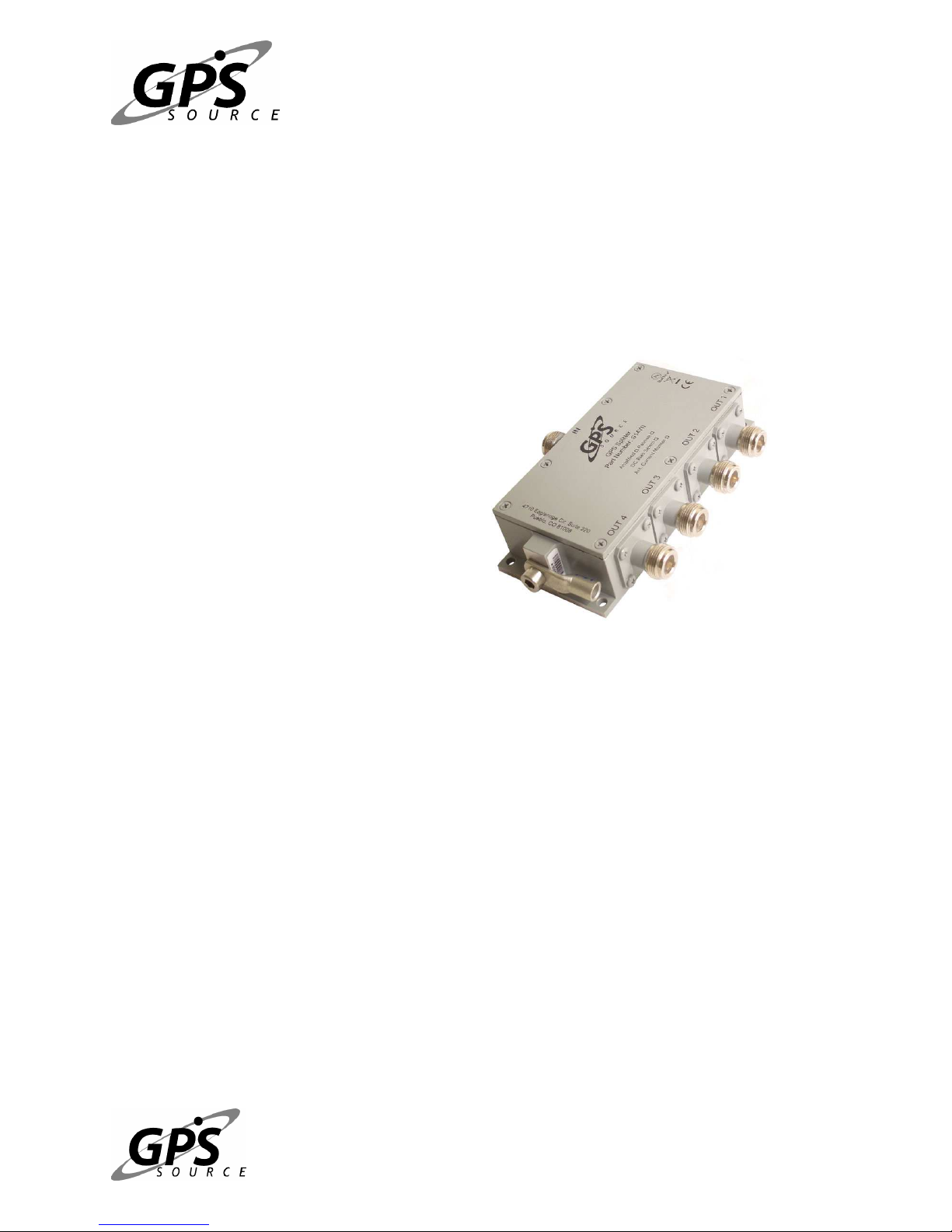
S14WI Splitter for Wireless
Infrastructure
1 of 9
Product User Manual
Features
•
• Active or Passive Options Available
••
•
• Optional Antenna Current Monitor
• •
and Alarm
• Optional Antenna DC Bias Select
• Pole-mount Environmental Housing
Available (IEC 529 level IP55)
• Surge Protection Available
(Tested to EN61000-4-5)
Description
Designed to eliminate the cost of multiple antennas and long cable runs in wireless base
stations applications, the S14WI can satisfy the demanding, high reliability requirements of the
wireless infrastructure market. The GPS Source S14WI is a high performance GPS signal
splitter that can be configured to monitor the GPS antenna current and provide an alarm
indication if the antenna is not operating according to spec. The S14WI also features an
optional antenna DC bias “Pick-&-Choose” circuit which allows for the active antenna DC input
to be applied to any or all of the RF outputs. With this option, one DC voltage will be chosen to
power the antenna while the other inputs will be switched to DC loads. If the selected DC bias
input should fail, the DC bias will be automatically switched to another DC input so as to ensure
an uninterrupted supply to the active antenna. The S14WI may be configured as a passive or
an active device, giving the network engineer the flexibility to specify the device gain and portto-port isolation. The S14WI may also be ordered with surge protection on all five ports and in a
sealed housing sufficient for many years of operation in external environments.
Your source for quality GNSS Networking (719) 561-9520
5/25/2007
Document number: 060-FSA-ABQ-AAS-AGZ
Solutions and Design Services, Now!
Rev. 001
Page 2

2 of 9
Table of Contents
Description ............................................................................................................................... 1
Functional Block Diagram ................................................................................................ 3
Operational Description..................................................................................................... 3
RF Signal Processing System ..................................................................................................... 3
Passive Option: ....................................................................................................................... 4
Amplified Option:................................................................................................................... 4
Amplified – High Isolation Option:........................................................................................ 4
Termination of Unused Ports:................................................................................................. 4
Bias-T’s:.................................................................................................................................. 4
Antenna DC Bias Select System................................................................................................. 5
Active GPS Antenna Monitoring System................................................................................... 5
Surge Arrestor System................................................................................................................ 6
Connecting the S14WI ........................................................................................................ 6
Performance Specifications............................................................................................ 7
Certifications and Approvals .......................................................................................... 7
Part Number ............................................................................................................................. 8
Mechanical ............................................................................................................................... 9
Your source for quality GNSS Networking (719) 561-9520
5/25/2007
Document number: 060-FSA-ABQ-AAS-AGZ
Solutions and Design Services, Now!
Rev. 001
Page 3
3 of 9
Functional Block Diagram
Figure 1 below illustrates the functionality of the GPS Source S14WI GPS Splitter. The S14WI
consists of an RF Signal Processing System (illustrated in Blue), a DC Bias Select System
(illustrated in Red), an Active GPS Antenna Monitoring System (illustrated in Green), and a
Surge Arrestor System.
RF In,
DC Out
Active GPS Antenna
Monitoring System
Pwr.
Supply
RF Choke
DC Blk.
S14WI GPS Signal Splitter
Active
or
Passive
Figure 1 S14WI Functional Block Diagram
DC Switching Circuit
DC Blk.
DC Blk.
DC Blk.
DC Blk.
RF Choke
RF Choke
RF Choke
RF Choke
RF Out,
DC In
RF Out,
DC In
RF Out,
DC In
RF Out,
DC In
Operational Description
RF Signal Processing System
The RF signal processing system consists fundamentally of three classical Wilkinson Splitter
elements that divide the RF signal from the antenna input evenly between four RF output ports.
There are several options that are available concerning the RF Signal Processing System.
These options are:
Your source for quality GNSS Networking (719) 561-9520
5/25/2007
Document number: 060-FSA-ABQ-AAS-AGZ
Solutions and Design Services, Now!
Rev. 001
Page 4

4 of 9
1. Passive
2. Amplified
3. Amplified - High Isolation
Passive Option:
In the Passive Configuration, the RF input from the antenna bypasses the amplification stages
and is passed directly to the input Wilkinson Splitter element. This splitter element divides the
RF signal evenly, resulting in 3dB (ideally) reduction in signal level at the output of each splitter.
The signal is then split again, resulting in four outputs, each output being 6dB (ideally) below the
input signal. In reality, since the Wilkinson Splitter elements are realized with non-ideal
components which have a finite Q, the signal reduction for each Wilkinson Splitter element is
approximately 4dB, resulting in an overall signal reduction through the splitters of approximately
8dB. When other losses are accounted for, such as losses in the RF connectors and the “BiasT’s”, the overall signal reduction through the passive configuration is approximately 9dB.
Amplified Option:
In the Amplified Configuration, the RF signal from the input is applied to two RF gain stages
prior to the Wilkinson Splitter elements. The first of these amplification stages provides
approximately 17dB of gain at a very low noise figure. The second stage provides additional
gain so as to ensure that the input port to any output port gain of the splitter is approximately
21dB.
Amplified – High Isolation Option:
In the Amplified – High Isolation Configuration, resistive, 50 Ohm signal attenuators are added
in the RF output paths to provide additional isolation between each RF port. This configuration
may be chosen if it is possible for spurious emissions from one GPS receiver on one port of the
splitter to cause interference with GPS receivers connected to other output ports. In the high
isolation configuration the input port to any output port gain of the splitter is approximately 10dB.
Termination of Unused Ports:
Note that in the Passive and Amplified (NON-High Isolation) configuration, all ports must be
terminated in 50 Ohms in order to ensure proper operation of the Wilkinson Splitter elements. If
all ports are not terminated properly, the S14WI input/output SWR and Gain/Loss may not meet
specifications.
In the Amplified-High Isolation configuration, the 50 Ohm signal attenuators provide substantial
isolation from open circuits on unterminated output ports. Consequently, RF outputs may be left
unterminated without adversely affecting the operation of the S14WI.
Bias-T’s:
GPS RF signal splitters are unique relative to other generic RF signal splitters in that they
typically operate in conjunction with an active GPS antenna (that is a GPS antenna that includes
an integrated Low Noise Amplifier). Consequently, a GPS RF signal splitter must have
provisions for managing the DC voltages to the active GPS antenna. These DC voltages are
typically applied to the center conductor of the RF coaxial cable which runs from the antenna
Your source for quality GNSS Networking (719) 561-9520
5/25/2007
Document number: 060-FSA-ABQ-AAS-AGZ
Solutions and Design Services, Now!
Rev. 001
Page 5

5 of 9
down to the application’s receiver(s). As such, each input and output port of the S14WI
includes a “Bias-T” functionality which allows for DC voltages to be applied on the center pins of
the RF connectors. In this arrangement, DC voltages for powering the antenna may be applied
to the center pin of the RF outputs. The DC voltage passes through the RF chokes to the DC
Bias Select System and on to the RF input connector to power the antenna. This DC voltage is
blocked from the RF section by DC blocking capacitors.
Antenna DC Bias Select System
The S14WI splitter requires that a DC voltage be applied to one or more of the RF output ports
by way of the RF connector center conductor. If DC voltages are applied to more than one of
the RF output ports, the S14WI DC Bias Select System will choose one of these DC inputs to
power the active circuitry of the S14WI and will also pass this DC voltage through the splitter to
the center conductor of the RF input port. The DC voltage available on the RF input port can
then be used to power the application’s active antenna. The DC voltages applied to the RF
outputs that are not chosen by the DC Bias Select circuitry will be automatically switched
through an RF choke to 200Ohm DC loads. The DC voltages may be applied to any or all of the
RF outputs; however, the DC Bias Select circuit will always select the DC voltage on the lowest
numbered RF port that has a DC voltage applied to power the S14WI and the application’s
antenna. If the chosen DC input were to be removed or fail, the DC Bias Select circuit will
automatically switch to the next higher numbered RF port to which a DC voltage is applied.
The S14WI requires that only one RF output port have an external DC voltage applied (i.e. the
device will operate properly even if any one, two, or three ports do not have a DC voltage
applied or if a DC voltage is removed from one of the ports). Ports that do not have an external
DC voltage applied or from which an external DC voltage is removed are internally pulled down
so as to ensure that false input voltage indications do not occur.
Example:
Assume DC voltages are applied to RF outputs 1, 3 and 4. In this scenario, the DC voltage on
port 1 will be used to power the S14WI and the application antenna. Ports 3 & 4 will be
switched to 200Ohm DC loads.
Now assume that the DC voltage on port 1 is removed. The S14WI will automatically terminate
the input internally with a pull down resistor and switch operation of the splitter and antenna to
the DC voltage applied to the next high numbered port with a DC voltage applied: port 3. Port 4
will remained switched to a 200 Ohm load.
Active GPS Antenna Monitoring System
Your source for quality GNSS Networking (719) 561-9520
5/25/2007
Document number: 060-FSA-ABQ-AAS-AGZ
Solutions and Design Services, Now!
Rev. 001
Page 6

6 of 9
The S14WI includes an option to monitor the status of the application’s active antenna and to
provide an alarm indication if the antenna’s current is not within a specified range. The default
current window for the S14WI is 15mA to 150mA (e.g. antenna current below 15mA indicates an
open circuit, above 150mA indicates a short circuit); however, for large volume orders, the
antenna current window may be specified to meet the customer’s specific requirements.
The S14WI samples the antenna current 16 times per second. So long as the average of four
samples are within the specified antenna current window, the S14WI will continue to operate
normally, passing the DC voltage applied to lowest number RF output on to the RF input. In this
mode, DC voltages applied to the remaining RF outputs are switched to 200Ohm DC loads. If
the average of four antenna current samples falls outside of the specified antenna monitor
current window, the DC voltage to the antenna is removed (open circuit) and all DC inputs are
switch to Pass DC. Since the DC path to the antenna has been opened, the DC current on all
four DC inputs will be at or near zero (less than 0.5mA for the passive configuration and less
than 5mA each for the active). In this alarm condition, all GPS receivers connected to the RF
outputs will also see very low antenna current draw, resulting in corresponding antenna alarm
conditions within each receiver.
Once in the alarm condition, the S14WI will periodically (every 60 seconds) attempt to reconnect DC power to the antenna. If the antenna failure condition persists, the S14WI will reenter the fault condition, repeating this cycle until the fault condition is removed.
Surge Arrestor System
The S14WI includes standard Gas Discharge Tubes and Transient Voltage Suppressors on
each RF input/output. Furthermore, provisions for high current grounding are included in the
metal enclosure of the device. The Surge Arrestor System is intended to provide a limited
capability to survive power line surges and voltage surges that may be induced by “near miss”
lighting strikes. Protection is rated to 4KA, according the IEC-61000-4-5. In order to ensure
proper protection of the device, the S14WI must be connected via a (8 AWG minimum) ground
cable to a low impedance ground.
Connecting the S14WI
When installing the S14WI, connect the coaxial cable feeding the active GPS antenna prior to
connecting RF outputs. Once the antenna coaxial cable is attached, coaxial cables with or
without DC voltages may be connected to the outputs. Note that at least one coaxial cable
connected any output of the device must provide a DC voltage suitable for operating the active
GPS antenna and the S14WI.
Note that in some instances, upon initial connection of the DC voltage, the S14WI may power
up in the “Antenna Fault” mode which will prevent DC voltage from being applied to the active
antenna. If this behavior is observed immediately after power up, wait for approximately one
minute. Proper operation should be restored by this time. If after 1 minute proper operation is
not observed, ensure that a “known-good” active GPS antenna that sinks a DC current within
the specified range is connected to the IN port of the S14WI via a “known-good” RF coaxial
cable.
Your source for quality GNSS Networking (719) 561-9520
5/25/2007
Document number: 060-FSA-ABQ-AAS-AGZ
Solutions and Design Services, Now!
Rev. 001
Page 7

Performance Specifications
For additional detailed electrical performance specifications, see the S14WI Datasheet.
Electrical Specifications, Operating Temperature -40 to 85oC
Parameter Conditions Min Typ Max Units
Freq. Range Ant – Any Port, Unused Ports - 50 Ω
(2)
Gain
-Amplified (Norm)
Ant – Any Port, Unused Ports - 50 Ω
(Gain may be specified by the customer)
-Amplified (Hi Iso.)
Loss-Passive Ant – Any Port, Unused Ports - 50 Ω
Input/Output SWR All Ports 50Ω
DC IN
Device Current
Ant/Thru Current
I
Monitor
(4)
I
OC
SC
Surge Protection
DC Input on any RF Output
Current Consumption of Active device, excludes
Ant. Cur.
(3)
Max source DC current through device 250 mA
Range for Open Circuit Threshold 15 75 Antenna
Range for Short Circuit Threshold
8/20us
(1)
1.3:1 2.0:1 -
Notes:
(1). Note that for proper RF performance, the S14WI must have all RF ports terminated
into a 50Ohm coaxial cable system or a 50Ohm load.
(2). Custom gain option available.
(3). Maximum current available from the DC source through the S14WI when output
of S14WI is short circuited.
(4). Open circuit and Short Circuit Current (IOC, ISC) may be specified by the customer
within the specified range.
(5). In-rush current shall not exceed 3A or exceed Isc for greater than 1ms
GPS Source, Inc. reserves the right to change or modify
product performance and specifications without prior notification.
(1)
(1)
(1)
7 9.0 9.5 dB
1.2 1.7 GHz
20
21
24
9 10 11
4 12 VDC
18 20
(5)
100 180
5 KA
7 of 9
dB
mA
mA
Certifications and Approvals
o
EMC/Emissions: FCC part 15B and R&TTE equivalent
o
Power Line Surge: IEC-61000-4-5
o
Safety/Low Voltage: EN60950-1
o
Environmental: IEC 60529, IP55
Your source for quality GNSS Networking (719) 561-9520
5/25/2007
Document number: 060-FSA-ABQ-AAS-AGZ
Solutions and Design Services, Now!
Rev. 001
Page 8

8 of 9
Part Number
Product:
1x4 Splitter for Wireless
(Std: Pass DC J1-Ant, J2,J3,J4 DC Blk.)
Gain Option:
A – Amplified
Axx – Custom Gain
Blank – Passive
H – Hi Isolation
Pick & Choose Option:
PC – Add Pick & Choose
Blank – Std. Config.
Antenna Monitor Option:
AM – Add Ant. Monitor
Blank – Std. Config.
Connector Options:
NM – N, Male
NF – N, Female
SM – SMA, Male
SF – SMA, Female
TM – TNC, Male
TF – TNC, Female
BM – BNC, Male
BF – BNC, Female
SB – SMB Jack, Female
SC – SMC Jack, Female
MX – MCX Jack, Female
For help in creating the part number to meet your exact needs, contact us at
Sales@gpssource.com or visit our website at www.gpssource.com .
S14WI
S14WI –––– A
S14WI S14WI
A –––– PC
PC –––– AM
A A
PC PC
AM–––– SF
AM AM
SF
SF SF
Your source for quality GNSS Networking (719) 561-9520
5/25/2007
Document number: 060-FSA-ABQ-AAS-AGZ
Solutions and Design Services, Now!
Rev. 001
Page 9

Mechanical
9 of 9
Your source for quality GNSS Networking (719) 561-9520
Solutions and Design Services, Now!
5/25/2007
Document number: 060-FSA-ABQ-AAS-AGZ
Rev. 001
 Loading...