

Page 1

031919-GPSIMOD-IOM REV E.docx
GLOBAL PLASMA SOLUTIONS
GPS-iMOD®
Installation
Operation &
Maintenance
Manual
10 Mall Terrace, Building C
Savannah, GA 31406
(912) 356-0115
www.globalplasmasolutions.com
Page 2
031919-GPSIMOD-IOM REV E.docx GPS, iMOD, iDetect-P and its logos are trademarks of Global Plasma Solutions, Inc. www.globalplasmasolutions.com
©2019 Global Plasma Solutions, Inc.
Thank you for purchasing a GPS-iMOD system from Global Plasma Solutions (GPS). The GPS-iMOD is a revolutionary product in the air purification
industry. The GPS-iMOD is manufactured from high quality components to prevent wear, does not require replacement and does not generate
ozone. The system is designed to provide a long, trouble free life and low cost of ownership.
HARDWARE PROVIDED BY GPS
Before you start, confirm the contents of your shipment contains all the parts ordered. Each GPS-iMOD system will consist of the following
components:
1. GPS-iMOD 15-watt power supply with multi-voltage input: (24VAC/0.5A; 120VAC/0.12A; 208-240VAC/0.065A).
2. GPS-iMOD 6’ flexible power cable with connectors and first electrode on the bar already attached. Custom length cables may have been ordered
and lengths may vary by application. More than 1 may be provided based on AHU size.
3. GPS-iMOD 6-inch modular sections provided per quantities ordered to achieve overall desired ionization bar length.
4. End cap for each iMOD assembly bar. End cap inserts into the last modular section of the bar to prevent contamination.
5. A minimum of 2 mounting magnets per bar for securing the GPS-iMOD to the cooling coil inlet or filter rack. Magnet quantity provided will increase
based on overall bar length. GPS recommends magnet spacing of about 16 inches.
6. Nylon screws and nuts for securing magnets to the front or back of the iMOD sections and metal screws for securing magnets to the top of the
iMOD sections where the bar can be mounted to the ceiling of an air handler.
HARDWARE REQUIRED BY OTHERS
1. Self-tapping sheet metal screws.
2. Electric wiring, junction box or receptacle to provide power to the GPS-iMOD power supply, optional air flow switch, optional door switch, optional
remote mounted ion detector sensor, or optional NEMA enclosure for power supply. Note: optional items may be included based on the items
quoted or provided in the purchase order.
INSTALLATION LOCATION
GPS recommends mounting the GPS-iMOD downstream of a MERV 6, 30% particulate filter to prevent unnecessary build-up of particulate on the
carbon fiber needle tips. Below is a list of locations to mount the GPS-iMOD in the preferred order.
1. The optimal location to mount the GPS-iMOD is between the particulate filter and the cooling coil. Mounting the GPS-iMOD in this location will
prevent particulate build-up. The GPS-iMOD mounted before the cooling coil will prevent bacteria, virus and mold from breeding on the cooling
coil as the ions will be pulled through the coil with the air flow.
2. Downstream of the particulate filters and the cooling coil in a location where condensate from the coil or a humidifier will not completely saturate
the bar. Whereas the iMOD bar is waterproof, the ionization will be reduced from the carbon fiber brushes if they become saturated with water
from condensate.
3. Before the particulate filters. Please note if the bar is mounted before the particle filters, the ionization will not go past the particle filters. In
healthcare applications, 2 sets of bars are suggested; one set on the coil inlet and one after the final filters.
MECHANCIAL INSTALLATION
For standard applications, there should be a quantity of 1 GPS-iMOD bar assembly on each coil up to 60 inches in height. The GPS-iMOD bar(s) should
be spaced a maximum of 60 inches apart to get optimal ionization coverage on the coils. The bar should be installed such that the entire finnedwidth of the cooling coil is spanned by the GPS-iMOD bar (see FIGURE 13).
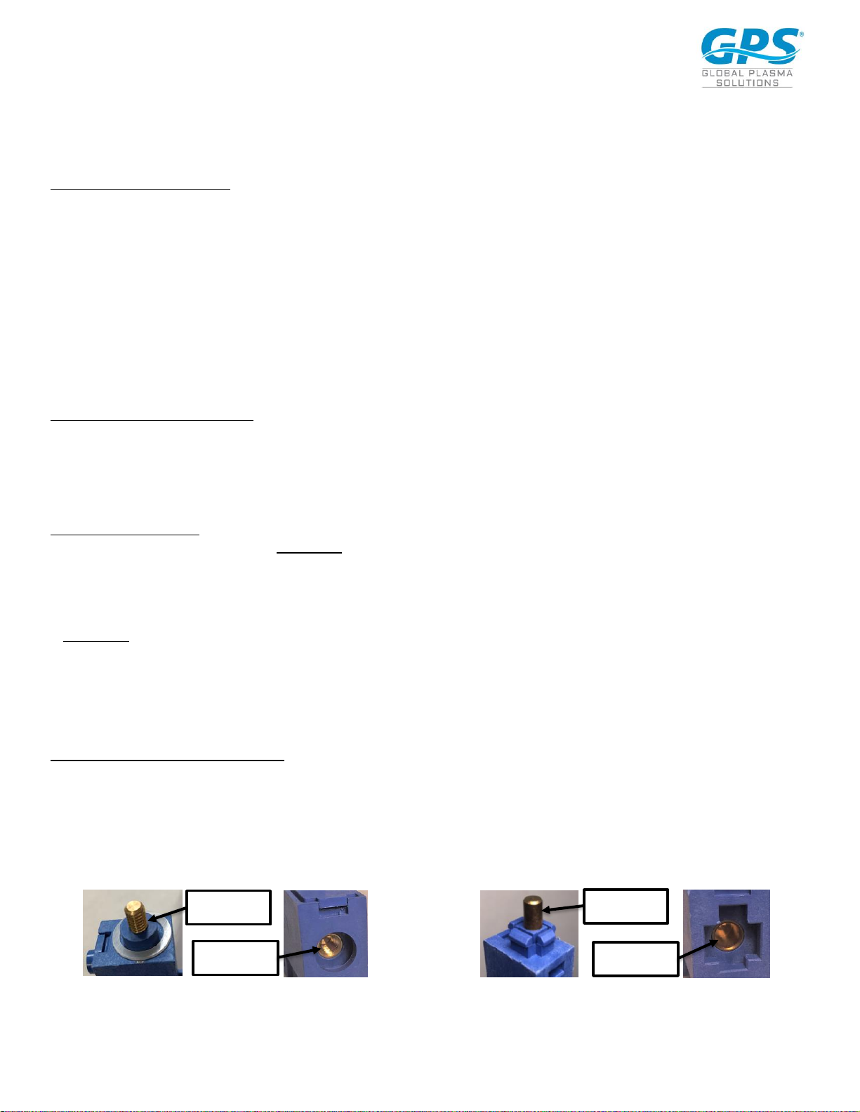
1. Determine which style of GPS-iMOD is being installed.
i. If using the screw-type iMOD, go to Step 1A (Refer to FIGURE 1 for GPS-iMOD screw-type with threaded post).
ii. If using the snap-type iMOD, go to Step 1B (Refer to FIGURE 2 for GPS-iMOD-S snap-type without threads).
FIGURE 1 FIGURE 2
Threaded
Post
Threaded
Receiver
Smooth
Post
Smooth
Receiver
Page 3
031919-GPSIMOD-IOM REV E.docx GPS, iMOD, iDetect-P and its logos are trademarks of Global Plasma Solutions, Inc. www.globalplasmasolutions.com
©2019 Global Plasma Solutions, Inc.
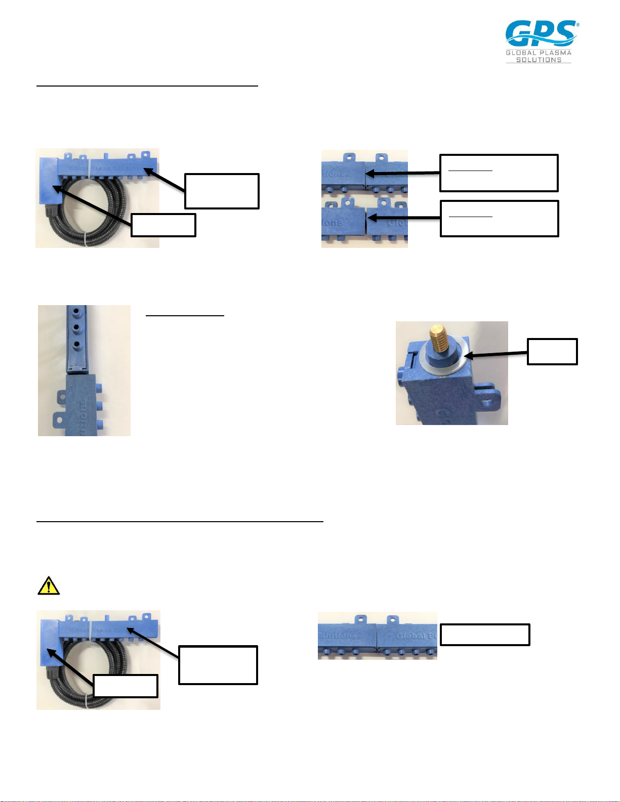
Step 1A – Assembly of screw-type GPS-iMOD
Once the mounting location has been determined, assemble the modular sections by inserting the male threaded post into the female receiver of
the first modular section already attached to the powerhead (see FIGURE 3) and tighten until the modular housings are securely butted to each other.
See FIGURE 4 below for correct assembly alignment. Please note, it should take 3-4 complete revolutions to assemble properly. Continue process
until all modules are assembled to the desired length of the bar.
FIGURE 3 FIGURE 4
Not all the bars will screw together and line up with the brushes pointing in the same direction without using excessive force that could damage the
module. Below are directions to assemble the bars to ensure alignment.
iMOD ALIGNMENT
When the sections do not align properly after they have been
securely adjusted, as shown in FIGURE 5, disassemble the section
and place nylon spacer(s) provided by GPS between the two
sections as shown in FIGURE 6. Use several if needed.
FIGURE 6
FIGURE 5
Once the spacer is placed over the male end of the device, twist the sections together until the parts are snug, and the carbon fiber brushes are
pointing in the same direction, as shown in FIGURE 4A. Please note, once the bars are assembled, there should be no “wobble” between the sections.
Proceed to 2.
Step 1B – Assembly of snap-type GPS-iMOD (GPS-IMOD-S)
Once the mounting location has been determined, assemble the modular sections by inserting the post-end of the iMOD-S into the receiver-end of
the first modular section already attached to the powerhead (see FIGURE 7). Attach iMOD-S sections, making sure they are properly aligned as shown
in FIGURE 8. Attach the iMOD-S sections by using a rubber mallet and carefully tapping with enough force to cause the modular sections to “snap”
together (see FIGURE 9). Set iMOD on hard, flat surface when assembling with mallet. Hold iMOD firmly while tapping with hammer to avoid slipping.
Do not hold iMOD between sections while assembling to avoid pinching.
FIGURE 8
FIGURE 7
Powerhead
First Modular
Section
FIGURE 4A. Proper
Assembly – NO GAP
FIGURE 4B. Improper
Assembly – GAP VISIBLE
Powerhead
First Modular
Section
Spacer
Proper Assembly
Page 4

031919-GPSIMOD-IOM REV E.docx GPS, iMOD, iDetect-P and its logos are trademarks of Global Plasma Solutions, Inc. www.globalplasmasolutions.com
©2019 Global Plasma Solutions, Inc.
CAUTION: Once iMOD-S sections are snapped together, they cannot be disassembled without breaking off the end piece.
Continue assembling the modular sections until you reach the needed length for the coil. After assembling the first 8
iMOD-S sections, lay the assembly on floor with the powerhead firmly butted against a rigid wall. See FIGURE 10. Continue
to add iMOD sections until you reach the required length of the assembly. Proceed to 2.
FIGURE 10
FIGURE 9 FIGURE 11
2. Once the last iMOD section is added, push the nylon end cap into the receiver end of the last iMOD piece. It will “snap” into place with proper
pressure. Refer to FIGURE 11.
Proceed to 3 under iMOD MOUNTING.
iMOD MOUNTING
3. The GPS-iMOD modular sections can be mounted using the included magnets and hardware, or they can be mounted using sheet metal screws
(not provided) through the integral molded brackets. There should be at least one magnet mounted on each end of the bar assembly and
depending on length of bar, additional magnets or sheet metal screws may be required. Refer to FIGURE 12. Nylon screws and nuts are provided
by GPS for mounting the magnets to the front or back of the bar.
FIGURE 12
4. When mounting the GPS-iMOD, the bottom of the GPS-iMOD should be level with top of the finned surface area of the coil as shown in FIGURE
13, with the carbon fiber brushes pointing towards the floor. Keep all metal away from carbon fiber brushes. The ionization bar should always be
mounted on the air-entering side of the cooling coil. Mounting the bar on the leaving side of the coil (drain pan and wet side) will not keep the
coil clean. The GPS-iMOD powerhead may be rotated to provide the best power cord routing based on the installation. Refer to FIGURE 14. When
more than one bar is required per coil, mount the second bar half way down the coil with the needles pointing towards the floor.
NOTE: The installing contractor will have to provide a piece of metal angle across the face of the coil to attach the GPS-iMOD if the coil finned surface
area is over 3 feet wide.
End Cap
Magnet
Page 5

031919-GPSIMOD-IOM REV E.docx GPS, iMOD, iDetect-P and its logos are trademarks of Global Plasma Solutions, Inc. www.globalplasmasolutions.com
©2019 Global Plasma Solutions, Inc.
FIGURE 13
FIGURE 14
POWER SUPPLY INSTALLATION AND WIRING
WARNING – DO NOT CONNECT POWER UNTIL VOLTAGE SELECTOR SWITCH INSIDE HOUSING IS CONFIRMED
TO BE IN THE CORRECT POSITION FOR THE PRIMARY POWER BEING APPLIED (See FIGURE 15).
The GPS-iMOD system requires a total of 15 watts to power up to 6 GPS-iMODs at any length. The power supply will accept 24VAC, 115VAC or 208240VAC at 50HZ or 60HZ. CAUTION!! The power supply has an internal voltage selector switch set to 115VAC from the factory, as shown in FIGURE
15. If 24VAC or 208-240VAC is required, move the selector switch to the proper position as shown on the circuit board or inside cover of the
power supply lid. DO NOT APPLY POWER until the switch position matches the power supplied. Based on voltage input or local electric codes, the
3-prong plug may be cut off and the three wires are as follow: White = Neural, Black = 24V, 110V or 208-240V (based on switch position) and Green
= Ground.
1. The power supply may be mounted to the internal or external wall of the air handler.
2. Find a suitable location within reach of the high voltage cable extending from the GPS-iMOD. Remove the four screws securing the lid of the
power supply.
3. Mount the power supply to the wall using sheet metal screws through the mounting tabs on the power supply.
4. One HV port in the high voltage (HV) section will be left open for attachment of the HV supply wire. Refer to FIGURE 16. Based on the jobsite
specific wiring route, access to the right, left or top side may be desired. Remove the plug from the port desired and fill the port not used with the
spare plug. DO NOT RUN HIGH VOLTAGE INPUT WIRES THROUGH THE CONTROL
PORTS AND DO NOT RUN CONTROL WIRING THROUGH HIGH VOLTAGE (HV) PORTS! REFER TO FIGURE 16.
FIGURE 15 FIGURE 16
HV Ports
Control Ports
Rotate connector arm up or leave down as
required for installation.
Voltage Selector
Switch
Jumper Wire
Page 6

031919-GPSIMOD-IOM REV E.docx GPS, iMOD, iDetect-P and its logos are trademarks of Global Plasma Solutions, Inc. www.globalplasmasolutions.com
©2019 Global Plasma Solutions, Inc.
5. Remove the top nut from the HV screw (FIGURE 17). DO NOT REMOVE THE BOTTOM NUT! Remove the plastic nut (FIGURE 18) from the end of
the high voltage cable. Next, push the HV wire through the desired port and place the plastic nut back over the HV cable. Place the electrical eye
connector over the HV screw and tighten down the top nut to secure. If there are multiple bars connected, place all electrical eye connectors
under the top nut prior to tightening. Push the HV connector into the HV port and tighten the plastic nut to secure in place (FIGURE 19). Once all
connections are made, replace lid or proceed to connect the control wiring.
FIGURE 17 FIGURE 18 FIGURE 19
CONNECTION TO BMS/BAS
The GPS-iMOD has an internal ionization output sensing circuit. The external GPS-iDETECT-P™ is not required but may be installed as an option.
Integral alarm “dry” contacts will close when the system is on and operating properly. To tie into the BMS/BAS for remote monitoring, use 18/2
twisted pair, SHIELDED, plenum rated cable and connect to the BMS/BAS ALARM contact terminals. Connect the cable shield to the ground terminal
as shown in FIGURE 20. The terminal block may be removed for ease of wiring. Keep the control wiring as far from the HV wiring as
possible. DO NOT RUN BOTH CABLES TOGETHER AND DO NOT ZIP TIE CONTROL WIRING TO FLEXIBLE HV CABLES!
FIGURE 20
CONNECTION OF GPS-iDETECT-P
1. Remove the red jumper wire between C and NO on the GPS-iDetect-P terminal block (see FIGURE 15 for jumper wire).
2. Using 300V, 18/4, plenum rated, SHIELDED cable wire between the GPS-iDetect-P power and normally open terminals and the GPS-iMOD power
supply GPS-iDetect-P terminal block as shown in FIGURE 20. Ground the 18/4 SHIELD to the ground terminal on the GPS-iDetect-P terminal strip
shown in FIGURE 20.
Only ground ONE end of the shielded cable.
Do not ground the end connected to the GPS-iDETECT-P sensor.
DO NOT RUN CONTROL WIRING WITH HV CABLES!
3. Mount the GPS-iDetect-P using the included 1” coated pipe clamp and secure to a GPS-iMOD section as shown in
FIGURE 21 using a nut and bolt.
HV Screw
and Nut
Top Nut
Removed
Final
Connections
Ground terminal for BAS 18/4 Shield on GPS-
iDETECT-P, if used. Please note, only ground
one end of shielded cable!
Ground terminal for BAS/BMS 18/2 Shield.
Please note, only ground the end of the
shielded cable inside the power supply! Do
not ground both ends of the shielded cable!
NUT
Page 7

031919-GPSIMOD-IOM REV E.docx GPS, iMOD, iDetect-P and its logos are trademarks of Global Plasma Solutions, Inc. www.globalplasmasolutions.com
©2019 Global Plasma Solutions, Inc.
FIGURE 21
4. When the GPS-iDetect-P senses output, the “Plasma On” light will illuminate on the front panel of the power supply and the BAS/BMS Alarm
Contacts will close. When using the GPS-iDetect-P in conjunction with the GPS-iMOD power supply, always connect to the BMS/BAS using the
BMS/BAS Alarm Contacts, not the contacts on the GPS-iDetect-P.
OPERATION
1. Once the voltage selector switch has been set, all HV wire(s) connected and iMODs mounted, turn the power switch to the “ON” position. When
the switch is turned “ON” the “Power ON” light will illuminate, letting the user know power is supplied and the GPS-iMOD system is energized.
Note: If a door switch, fan interlock switch or air flow switch are in series with the power, the system may not turn on until all safeties are closed.
When power is supplied and the internal or optional remote mounted GPS-iDetect-P is sensing output, the “Plasma On” light will illuminate.
2. The internal BAS Alarm Contacts will close proving system operation to the BMS.
3. Using a standard non-contact voltage meter, place it near the ion needles and prove there is ion output. An optional ion meter can be purchased
from GPS and actual ion output values can be measured. A permanent mount ion detector with BAS interface may be provided as an option for
24/7 output monitoring.
STARTUP/TESTING
1. Once the entire system is mounted and wired, energize the system by turning the on/off switch to the “on” position. The green power “ON” LED
and “PLASMA ON” LED should illuminate. If the PLASMA ON does not illuminate, confirm the red jumper is installed between C and NO on the
GPS-iDetect-P terminal block, as shown in FIGURE 20. If an external sensor is used, confirm it is on and operating.
2. Using a high voltage probe similar to a BK Precision Plus 28A, connect the probe to a multi-meter, connect the ground clamp, and measure the AC
high voltage (AC not DC) at the 6 inch modular stingers. Insert the tip of the probe into one of the brush clusters and confirm the voltage is greater
than 4,000 VAC. Please note, most probes provide a 1000:1 step down. As an example, a display of 4.0 would be 4.0 x 1000 = 4,000 VAC. The
typical range of voltage is 4,000VAC to 7,000VAC, and the actual voltage will depend on the length and quantity of bars attached.
MAINTENANCE
The GPS-iMOD system has been designed for minimum maintenance. Below are the steps to ensure a long trouble-free life:
1. On an annual basis, turn off power and use isopropyl alcohol and a nylon (wire free) brush to gently clean the needles.
2. Use a soft cloth with isopropyl alcohol and wipe any debris off the GPS-iMOD outer bar and spaces between needle housings.
3. Note: In tobacco smoking environments, the GPS-iMOD will require more frequent cleaning based on the filter efficiency prior to the GPS-iMOD
system.
TROUBLESHOOTING
1. Power supply “Power On” light not illuminated when the power switch is in the “ON” position.
1A. Check that all safeties are closed and there is primary power applied to the power supply. If light will still not illuminate, remove power and
energize after five minutes. The GPS-iMOD system uses an internal auto-reset circuit breaker. Either a voltage surge or high temperature/load
condition can trip the circuit breaker. If the “Power On” light is off and the “Plasma On” light is “On,” the “Power On” light may have burned
out. Contact your local Representative or the GPS factory to have your power supply repaired or replaced.
2. No Ionization Output.
2A. Confirm the power supply is operating properly per step 1A above. Confirm the HV cables are inserted and secured properly. Confirm the
needles are clean and free of debris.
Page 8

031919-GPSIMOD-IOM REV E.docx GPS, iMOD, iDetect-P and its logos are trademarks of Global Plasma Solutions, Inc. www.globalplasmasolutions.com
©2019 Global Plasma Solutions, Inc.
GLOBAL PLASMA SOLUTIONS, INC.
 Loading...