


User Manual
User Manual
[EN-Series LCD Video Wall]
EN-Series
Video wall
Models
EN46MSS
EN46MSU
EN46HSS
EN46HSU
EN55MSS
EN55MSU
EN55HSS
EN55HSU
EN55HLS
EN55MLU
Before operating the unit, please read this manual thoroughly, and retain it for future reference
www.gpous.com
1

User Manual
Table of Contents
EN-Series
Video wall
1. Instructions
2. Safety precautions for “EN”-series systems
3. Mechanical Layout
4. Connections
5. SICP
6. Remote Control
7. Viewing the Menus
8. ACR Agent Network
9. ACR Monitor
10. Specifications
www.gpous.com
2
EN-Series
User Manual
Video wall
Notice
1. When disconnecting the display from an electrical outlet, the plug must be pulled out from the
socket. Do not remove power cord from outlet by pulling from the cord. Pull from the plug head.
2. WARNING – To reduce the risk of fire or electric shock, do not expose this appliance to rain or other
forms of moisture.
3. Display must not be exposed to liquids via dripping or splashing. Please do not place liquid –filled
items such as vases near the display.
4. Use only a properly grounded plug and receptacle.
5. CAUTION – These instructions are for use by qualified service personnel only. To reduce the risk of
electric shock, do not perform any service other than that contained in the operating instructions
unless you are qualified to do so.
CAUTION
RISK OF ELECTRIC SHOCK
DO NOT OPEN
CAUTION : TO REDUCE THE RISK OF ELECTRIC SHOCK,
DO NOT REMOVE COVER (OR BACK).
NO USER-SERVICEABLE PARTS INSIDE.
REFER SERVICING TO QUALIFIED SERVICE PERSONNEL.
This symbol is intended to alert the user to the presence of insulated
“dangerous voltage” within the product’s enclosure that may be of sufficient
magnitude to constitute a risk of electric shock to persons.
This symbol is intended to alert the user to the presence of important
operating and maintenance (servicing) instructions in the literature
accompanying the product.
www.gpous.com
3

EN-Series
User Manual
Important Safety Instructions
1. Read these instructions.
2. Keep these instructions.
3. Heed all warnings.
4. Follow all instructions.
5. Do not use this product near water.
6. Clean only with dry microfiber cloth.
7. Do not block any ventilation openings. Install in accordance with the manufacturer’s instructions.
8. Do not install near any heat sources such as radiators, heat registers, stoves, or other display
(including amplifiers) that produce heat.
9. Do not remove ground prong from three-pronged plugs. If your outlet will not accept three-pronged
plugs, consult an electrician for replacement.
Video wall
10. Protect the power cord from being walked on or pinched, particularly at plugs, convenience
receptacles, and the point where they exit from the display.
11. Only use attachments/accessories specified by the manufacturer.
12. Use only with the cart, stand, tripod, bracket, or table specified by the manufacturer, or sold with the
display. When a cart is used, exercise caution when moving the cart/display combination to avoid
injury from tip-ov er.
13. Unplug this display during lightning storms or when unused for long periods of time.
14. Refer all servicing to qualified service personnel. Servicing is required when the display has been
damaged in any way, such as power-supply cord or plug is damaged, liquid has been spilled or objects
have fallen into the display, the display has been exposed to rain or moisture, does not operate
normally, or has been dropped.
15. Do not expose this display to dripping or splashing and ensure that no objects filled with liquids, such
as vases, are placed on the display.
16. To completely disconnect this display from the wall outlet, disconnect the power supply cord plug
from the AC receptacle./wall socket
17. The mains plug of the power supply cord shall remain readily operable.
18. An display with CLASS I construction shall be connected to a wall socket outlet with a protective
grounding connection.
19. Note: Prolonged use of headphones at a high volume may cause damage your ears.
20. Notice to users : This is a Class A digital device
21. This device is designed for commercial use and features safety certificates for electromagnetic
interference (EMI). Users should be mindful of EMI issues.
www.gpous.com
4

User Manual
Instructions
Thank You for Purchasing our Product
This manual describes how to use the product and provides safety guidelines and best
practices. Please read the manual carefully before using it.
After reading this manual, please retain for future reference.
If you have any questions or a problem occurs, please contact either the company you
purchased this product from or an authorized service center.
Displaying static images for an extended period of time may cause a burn-in
effect.
EN-Series
Video wall
Burn-in effect and the faults in brightness and picture elements caused by
extended display of static images are not subject to warranty coverage.
Multivision Features
Wide flat screen with unparalleled display quality and dependability
Easy to install and move due to its thin design.
True commercial-grade reliability
Accessories
CD Remote
DVI Cable
www.gpous.com
VGA Cable
Batteries (AAA x 2)
RS232C Cable Power Cable
5

User Manual
Cautions For Consisting Series System
Environmental conditions for installation
Since the panel is very sensitive to physical impact, installation requires considerable caution.
Minimum clearance (4 inches) on top/bottom/right/left of video wall array must be secured for
proper ventilation. Installation must avoid airtight or nearly airtight places. Improper ventilation
causes malfunction and shortens product lifetime via rapid internal temperature increase. If EN-
series displays must be installed in a poorly ventilated area, openings or fans must be provided to
keep the internal temperature between 32~95 ℉.
Please make sure to grounded (Earthing) AC power plugs and sockets.
Considering EN-Series Max power consumption, check the main electric specification.
EN-Series
Video wall
Clearance for Ventilation
When you install EN-Series, make sure there is at least 8inches clearance on all sides
(top/bottom/left/right) for effective ventilation and do not seal off the perimeter of EN-Series video
wall arrays.
If EN-series sets are installed at the locations with poor ventilation, the internal temperature can be
rise rapidly, causing frequent malfunctions and rapid reduction of the product life.
8inch
8inch
8inch
8inch
Wall-Embedded EN-Series Displays
In case of clearance <8 inches on each side of the display wall, make sure cooling fans are in place
at the upper part of the array to maintain internal temperature within the recommended threshold.
www.gpous.com
6

User Manual
Mounting on a wall surface
EN-Series
Video wall
Please secure minimum clearance as shown in the picture for adequate ventilation and
technical service.
Ventilation space in front of EN-Series displays must be furnished for heat dispersion. If the area
in front of EN-Series displays must be sealed, there must be consideration for the heat dispersion
on the rear side of EN-Series to compensate.
Precautions for installation
During installation, do not apply pressure to any surface of the panel. Damage to the panel may
result from external pressure or even minor impact to the panel. Physical and cosmetic damage to
displays is not covered under warranty.
0.1mm
www.gpous.com
7

User Manual
Please ensure alignment on the z-axis for a level plane across adjacent panels (as shown in the
diagram below). If precautions are not heeded, GPO US will not accept responsibility for any
Failure due to such installation errors.
EN-Series
Video wall
Do not apply excessive external pressure to panels during installation.
There is no warranty coverage for any damage arising from external
pressure/impact.
Do not cover fan ventilation holes
Carefully install EN-Series not to cover the fan air holes with any structural object.
If the holes are covered with anything, the inner temperature can be raised rapidly and it
can cause malfunctions
www.gpous.com
8

User Manual
Please retain the following instructions for panel protection
This product can be damaged even with minor impact.
Please keep following instructions for future reference when carrying or storing the products.
EN-Series
Video wall
If you need to stand LCD up,
you must use handles on
the rear and pull/raise
upward slowly so that the
LCD panel does not touch
the ground or floor.
If you need to lay the LCD
in a face-down position,
please use shock-absorbing
pads under the LCD panel
surface.
If you need to lay down LCD
in a panel face-up position,
please be cautious and
avoid falling objects on the
surface of the LCD.
Handle with Caution
Shock/Impact on the set’s sides will result in internal circuit damages.
The edges of the panel are fragile. Use shock-absorbing pads or rugs when laying the
product down.
Please do not allow the LCD
to stand alone. It may fall
or slip be broken or
damaged. Keep hands on
the LCD when it is in this
position.
www.gpous.com
Do not lean the LCD on a
bezel edge. This may result
in damage to the bottom
bezel of the LCD.
9
Do not lean the LCD toward
a bezel corner. This may
lead to panel damage.

User Manual
How to carry the product
At least two people are required to carry the display. When carrying the product
upright, please hold the handles on the rear as well as the bottom of the displa y
simultaneously for stability.
EN-Series
Video wall
When carrying the product with the panel positioned upwards as shown below,
please hold as shown in the diagram.
Application information
If static images are displayed on the screen for extended periods of time, image retention
(burn-in) can result.
Please retain the following instructions to optimize the lifetime and functions of the product.
www.gpous.com
10
User Manual
Mechanical Layout
EN-Series
Video wall
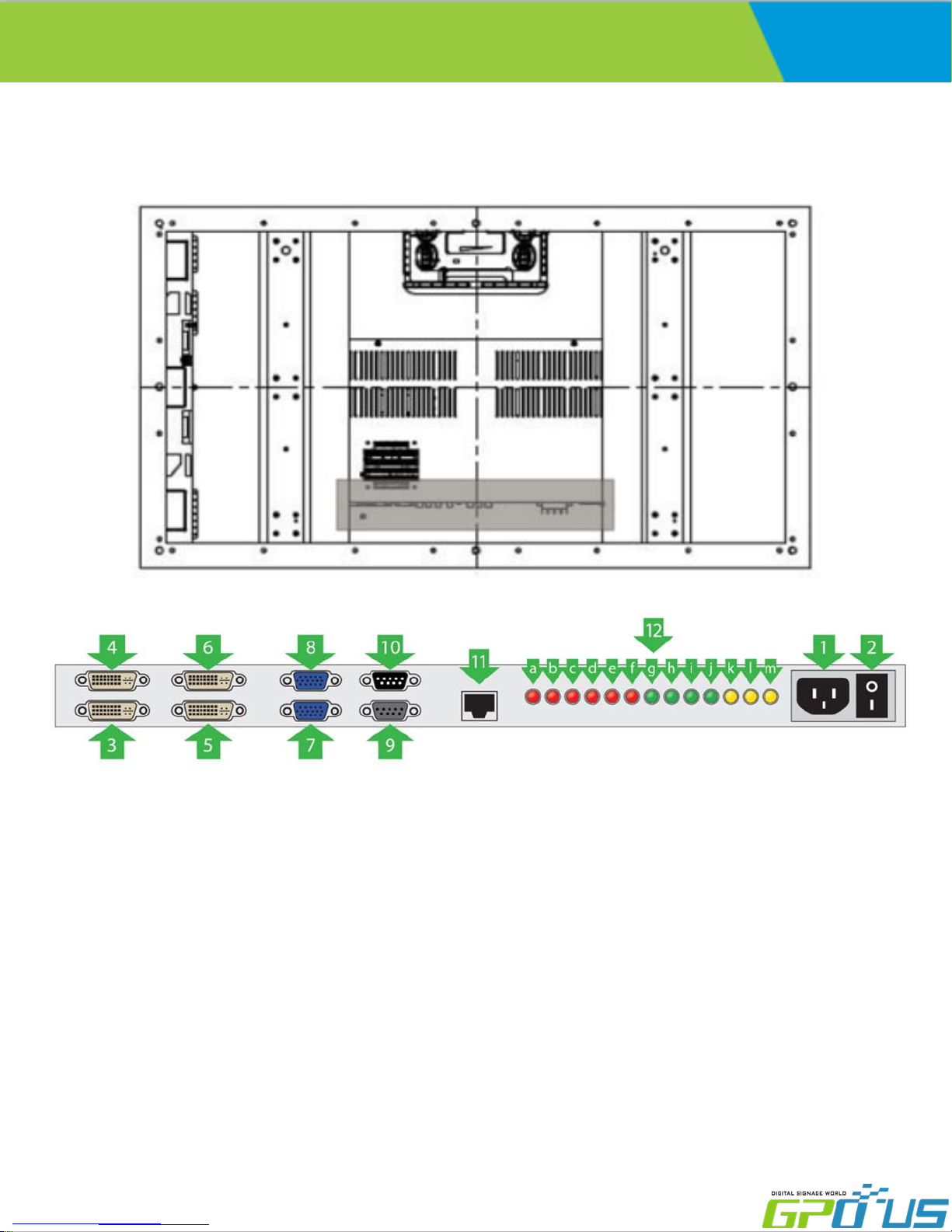
1. AC Power S/W On/Off
2. AC Power In (100V ~ 240V)
3. DVI 1 Input
4. DVI 1 Output
5. DVI 2 Input
6. DVI 2 Output
7. VGA Input
8. VGA Output
9. RS-232 Output
10. RS-232 Input
11. LAN Input
www.gpous.com
a. LED(RED) : LAN Connection Display
b. LED(RED) : Back light On(Lux) Display.
c. LED(RED) : Over Temperature Display.
d. LED(RED) : Active Power On Display.
e. LED(RED) : Active Back light On Display.
f. LED(RED) : Active Back light Dimming On Display.
g. LED(GREEN) : Active DC24V Input Display.
h. LED(GREEN) : Active DC12V Input Display
i. LED(GREEN) : Active DCM5V Input Display
j. LED(GREEN) : Active DCS5V Input Display
k. LED(YELLOW) : Source Input 1 Display.
l. LED(YELLOW) : Source Input 2 Display
m. LED(YELLOW) : Source Input 3 Display
11

User Manual
EN-Series
Video wall
1. IR
- Aim the remote control towards this spot on the LCD Display.
2. LED Indicator
- LCD Power Status display(On : BLUE / Off : RED)
3. OSD KEY Input(Power / Menu / Source / Left / Right / Up / Down)
a) Power : Turns the LCD Display On/ Off.
b) Menu : Displays the main On-Screen menu.
c) Source : Select Input Source
DVI DVI 2 PC
d) Left/Right : Moves from one menu item to another horizontally or adjusts
selected menu values. Adjusts the audio volume.
e) Up/Down : Moves from one menu item to another vertically or adjusts
selected menu values.
www.gpous.com
12

User Manual
Connections
Cabling(DVI 1)
EN-Series
Video wall
Cabling (DVI 2)
www.gpous.com
13

User Manual
Cabling (VGA)
EN-Series
Video wall
Cabling (RS-232)
www.gpous.com
14
User Manual
Remote Control
EN-Series
Video wall
1
3
4
6
8
2
5
7
9
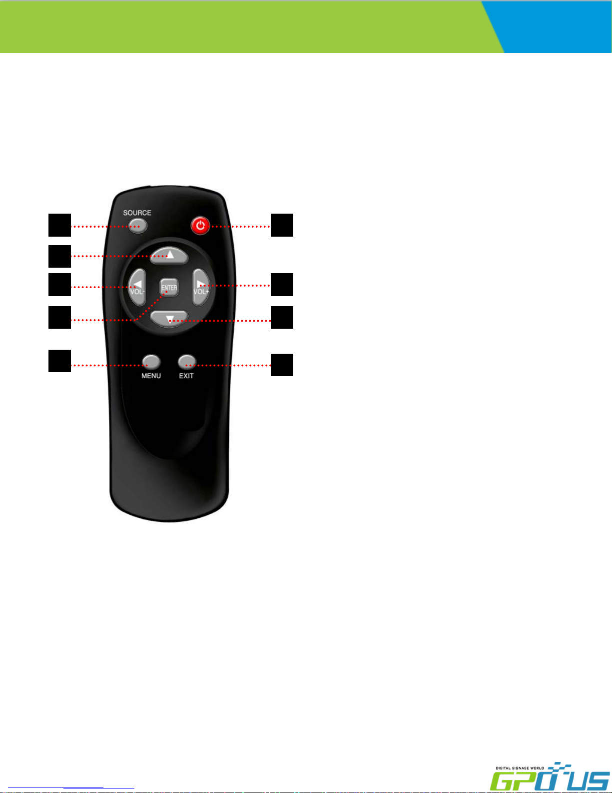
1. SOURCE : Select Input Source
-DVI 1-> DVI 2-> PC
2. POWER : Turns the LCD Display On and Off
3. UP : Control the UP cursor in the menu
4 LEFT : Control the LEFT cursor in the menu
5 RIGHT : Control the RIGHT cursor in the menu
6 ENTER : Control the ENTER cursor in the menu
7 DOWN : Control the DOWN cursor in the menu
8 MENU : Displays the main On-Screen menu
9. EXIT : Exit the On-Screen menu
www.gpous.com
15

User Manual
Viewing the Menus
EN-Series
Video wall
Press the MENU button.
The OSD menu is then displayed on the screen. Left side has five icons: Picture, Sound, Setup and PIP.
Changing the Picture Standard
1. Press the MENU button to display the menu.
2. Press the ▲ or ▼ button to select Picture, then press the ENTER button.
3. Press the ENTER button twice.
4. Select the required mode by pressing the ▲ or ▼ button, then press the ENTER button.
➢ The settings values may vary depending on the input source. [Ex: DVI, VGA(PC)]
5. Press the EXIT button to exit.
www.gpous.com
16

User Manual
Customizing the Picture Settings
Displays feature several setting options that allow you to control the picture quality.
EN-Series
Video wall
1. Press the MENU button to display the menu.
2. Press the ENTER button.
3. Press the ▲ or ▼ button to select Custom, then press the ENTER button.
4. Select the required mode by pressing the ▲ or ▼ button, then press the ENTER button.
5. Select the required option by pressing the ▲ or ▼ button, then press the ENTER button.
6. When you are satisfied with your setting, press the ENTER button.
7. Press the EXIT button to exit.
-Brightness – Contrast– Color – Tint –Sharpness (Tint NTSC only)
Press the ◀ or ▶ button until the desired setting is reached
www.gpous.com
17

User Manual
EN-Series
Video wall
www.gpous.com
18

User Manual
EN-Series
Video wall
www.gpous.com
19

User Manual
EN-Series
Video wall
www.gpous.com
20
User Manual
EN-Series
Video wall
www.gpous.com
21

User Manual
EN-Series
Video wall
www.gpous.com
22

User Manual
EN-Series
Video wall
www.gpous.com
23

User Manual
EN-Series
Video wall
www.gpous.com
24

User Manual
EN-Series
Video wall
www.gpous.com
25

User Manual
EN-Series
Video wall
www.gpous.com
26

EN-Series
User Manual
Video wall
SICP (Serial Interface Communication Protocol)
This document defines all the command and messages exchanged between the Master (a PC or the other
controller) and the Slave (the displays).
It also describes the ways to send or read the commands or the messages.
1. Protocol definition
SICP stands for “Serial Interface Communication Protocol”.
The protocol is specifically designed to allow data communication in half duplex multi-point environments,
but it can also be used for half duplex point-to-point RS-232C communication.
2. Communication characteristics
A half duplex communication is implemented starting from the concept of a master-slave structure, where
the display is supposed to be the slave.
The first action is always taken by the master, which can be either a PC or any controlling device (acting as
server) interfaced to the monitor. After sending a command or a request in the appropriate format the
master receives from the slave an acknowledgement, which tells the transmitter whether the command is
not valid (or not executable, anyway) or it is accepted. In case of a request, the requested information is sent
back and it becomes the acknowledgement by itself.
3. How to connect a external equipment
Female Pin number Male Pin number
2 <------------------------------------------------------> 2
3 <------------------------------------------------------> 3
5 <------------------------------------------------------> 5
4. Hardware Protocol
Baud rate : 9600 bps
Data bits : 8 bit
Parity bits : None
Stop bits : 1 bit
Handshake : None
www.gpous.com
27

User Manual
How to Install SICP
1. Introduction
This manual booklet describes how to manage and utilize the product (Video Wall set) through remote control
by RS232 protocol. This will introduce SICP V4.01 (Software that enables you to control the Video Wall) and
various applications will be possible with this software. As per different way of customizing, the functions and
specifications of each product may vary.
Notice: Please extract VBRunTimesR7.zip and install the program for VISTA, WIN7/8 before installing SICP.
2. Installing SICP V4.01
Run the file named “SICP 4.01_Set up.exe” and follow the instruction below.
If you have SICP program installed previously, delete the previous one and re-install the new one.
EN-Series
Video wall
Press “Next”
Wait until the installation is complete.
www.gpous.com
Select the folder you wish to save the file in.
Press “Install” if you are ok with the designated folder.
Once installation is complete, go to “Start” Menu ->
Programs -> SICP V4.01 to run the program
28

User Manual
3. Running SICP V4.01 and Structure
Go to “Start” Menu -> Programs -> SICP V4.01 to run the program.
EN-Series
Video wall
1. Network IP Setting: Controls IP Setting.
2. Com Mode: Selects the COM Port Mode.
3. Horizontal & Vertical: Select Horizontal & Vertical count of sets in array.
4. Communication: Select the COM Port connected to the PC.
5. Panel Configuration: Indicates information such as display configuration, source,
Set ID and display sequence number.
6. Set ID: Shows the Set ID selected for control.
7. Control Button: Set of control buttons/functions.
8. Edit tools: Set of edit tools.
9. Progress Bar: Shows the status of RS-232 communication.
www.gpous.com
29

EN-Series
User Manual
4. Connect & Disconnect
- Users can connect RS-232 input and control from your PC using the RS232 Cable.
- Select the Port into which PC is connected (refer to ③ in the image on previous page) and click
“connect” button.
If connected properly, the indicator in box ④ will turn BLUE (from RED). If not connected properly, one of
the following messages will appear:
*Unable to open serial port: The port may not be available on your PC, or another program may be
running under this port.
*Cannot connect with Easy DID System: RS232 Cable may not be connected properly or Set ID may be
incorrect. Re-check on Set ID.
5. Multi-vision Control
You can control each display separately. First, select the display you wish to control by selecting Set ID. You
may click on it (Refer to box ④ in the image on the previous page) or select it from the drag-down menu
(Refer to ⑤ in the image on the previous page). Users may conduct the following functions on the selected
set:
Video wall
1) Basic Control
- Select Control Tab
Power Control: Powers the Set On/Off
Source Control: Selects Source
Sound Mute: Turns Mute On/Off
Lock Mode: Locks or unlocks the IR/control key.
www.gpous.com
30

User Manual
2) Virtual Remocon (Remote Control)
EN-Series
Video wall
- Select Remocon Tab
- This virtual remote controller controls sets (displays)
via RS-232.
Note: Functions in Slide Tab will be described
in “6. Slide Function”
3) Color Setting
- Users may access the “Color Setting” mode only after
entering Supervisor Mode. In order to enter
Supervisor mode, go to “Control Mode” in the toolbar
(top) and select “Setting Mode”
- Hot key: Ctrl+F2.
- Click “OK”
- Adjust color val ues (0~ 255) . The color will be
optimized during production & Quality Assurance.
Adjusti ng the color is not recommended without
prior consultation with GPO US.
www.gpous.com
31
User Manual
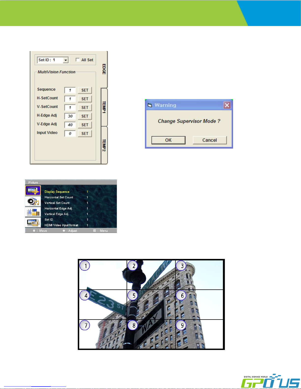
4) Edge Setting
EN-Series
Video wall
- Users can access “Edge Setting” only if
after entering Supervisor Mode. In order to enter
Supervisor mode, go to “Control Mode” in the
tool bar (top) and select “Setting Mode”
- Hot key: Ctrl+F3.
- Press “OK”
- Commands writable only (not readable).
<OSD Menu>
< Others >
- Display Sequence: position of display within context of the array (example below)
www.gpous.com
32

EN-Series
User Manual
- H-Set Count (Horizontal Set Count): Number of displays in array horizontally (counting left-to-right)
E.g. Diagram of array on previous page shows H-Set Count of “3”
V-Set Count (Vertical Set Count): ): Number of displays in array vertically (counting top-to-bottom)
E.g. Diagram of array on previous page shows V-Set Count of “3”
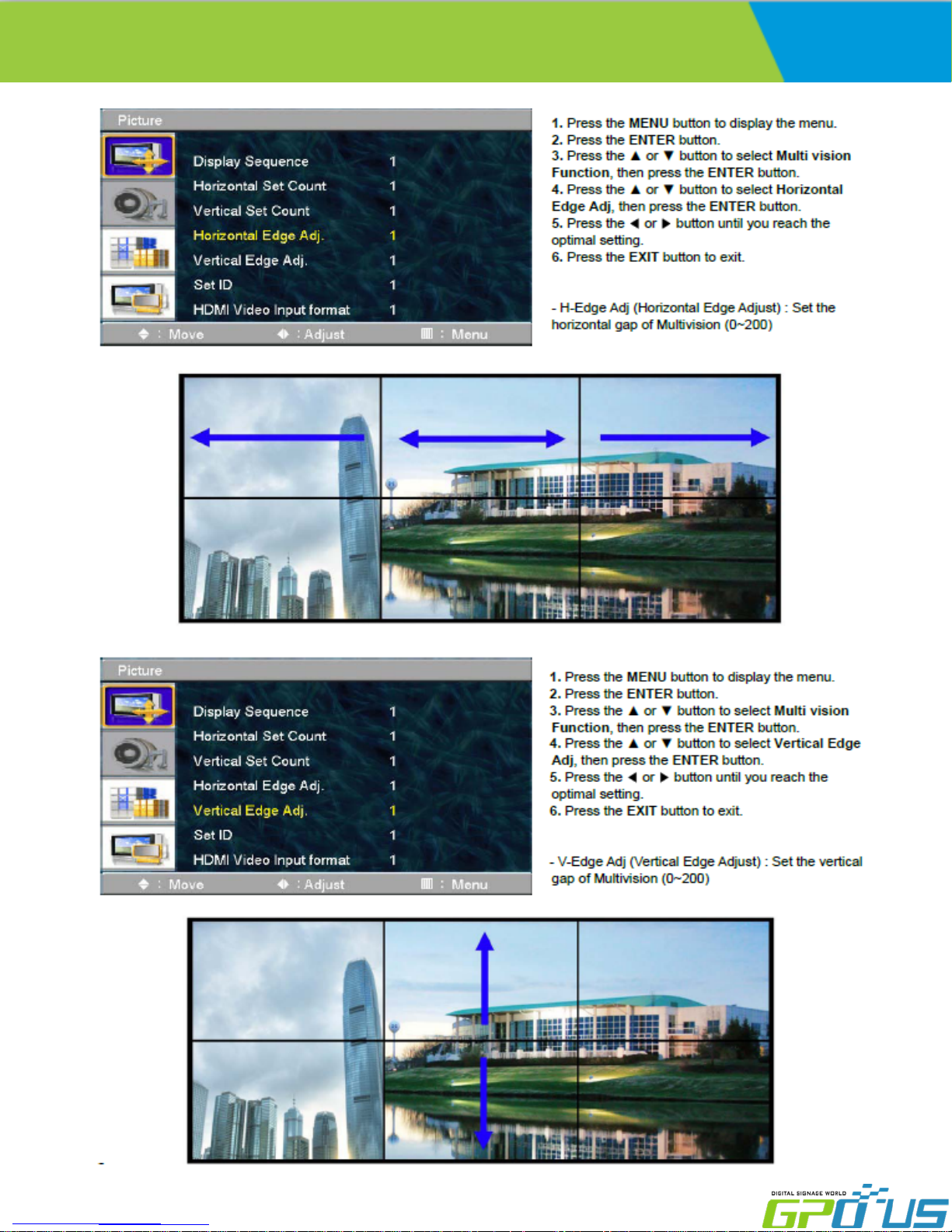
- H-Edge Adj (Horizontal Edge Adjust): Set the horizontal gap between displays in Video Wall (value range:
0~200)
Video wall
- V-Edge Adj (Vertical Edge Adjust): Set the vertical gap of displays in Video Wall (0~200)
www.gpous.com
33

EN-Series
User Manual
- HDMI Video Input format: Select video format of HDMI input data
0: RGB444
1: YPbPr444
2: YPbPr422
*HDMI Video Input format issues often manifest themselves in the form of a magenta/pink tint on display
panels. If this issue arises, check the type of source being used. If, for example, a Blu-Ray player is being
used, the HDMI Input Format on the displays must be set to “1” (default value is “0”).
1. Click “Control
2. Select “Other
Video wall
Mode”
setting “mode
www.gpous.com
3. Change the input
video format. (Ex. PC :
0, Blue-ray player: 1)
34

User Manual
6. Slide Function
1) Edit
EN-Series
Video wall
Example> When users wish to display a 5X5 background from DVI input and display 3X3 (in the center) from
VGA input.
- Click on Edit box as described in ① on the image above.
- Select PC as described in ② on the image above.
- Select the area by clicking and dragging as described in ③ of the image above.
- The complete image will appear as the image on the top/right.
# Send: Press “Send All” in order to test the setting you made so that you can decide if the adjustments are
satisfactory.
# Initialize: Select DVI in Edit tool and press “Set All” in order to initialize.
www.gpous.com
35

User Manual
# Add & Delete in Slide Schedule
EN-Series
Video wall
Slide (Layout) scheduling: Users set intervals/schedules for
each “slide”/layout separately.
Users cannot change the sequence of play after initial scheduling,
so the schedule must be arranged n order prior to Start.
Add : Insert the edits (slides)
- Remove : Remove slide
- Remove All : Remove the entire slide schedule
2) Play
Click the “Start” icon (refer to the image above) to begin schedule and click “Stop” icon if you wish to stop the
scheduled cycle of slides/layouts.
- Repeat: Check “Repeat” to loop schedule continuously.
3) File Management
Users may save layouts and replay the saved schedules. Users must save after completing scheduling.
- Save a file: Go to “Slide File” (top left of SICP program GUI) and press “File Save” in order to save the file in
the folder you wish to select. Basically, the file format is *.sld.
- Open a file: Go to “Slide File” and press “File Open” in order to open the slide you wish to play.
www.gpous.com
36

User Manual
5. Transmission Formats
This is the format that the computer will send to the display to execute commands .
The format for this command transmission is as follows:( total 13 byte )
ex) <STX>001PWRWOFF0<ETX> ( Set ID : 1 , Power Off Send )
STX ID1 ID2 ID3 CM1 CM2 CM3 R/W DA1 DA2 DA3 IND ETX
0x0f 0 0 1 P W R W O F F 0 0x0d
Hex ASCII (capital letter) Hex
- STX : Start of Text ( 0x0f )
- ID1 ~ ID3 : Set ID ( 001~100 )
- CM1 ~ CM3 : Command ( PWR, MIN, MUT,RML,KPL…… )
- R/W : Read/Write
- DA1 ~ DA3 : Data ( Values )
- IND : Index
- ETX : End of Text ( 0x0d )
Only use “Read”(R) or “Write” (W) as set forth in this document
EN-Series
Video wall
6. OK Acknowledgement
The acknowledgement will be sent by the display to the computer to verify that the command has
been successfully received and executed. This format for this acknowledgement is as follows:
ex) <STX>001PWR#OFF#<ETX> ( Set ID : 1 , Power Off Acknowledgement )
STX ID1 ID2 ID3 CM1 CM2 CM3 R/W DA1 DA2 DA3 IND ETX
0x0f 0 0 1 P W R # O F F # 0x0d
Hex ASCII (capital letter) Hex
7. Error Acknowledgement
The Error Values will be sent by the display to the computer to verify that the command has
been successfully received and executed.
This format for this Error Values is as follows:
ex) <STX>001PWRERROR<ETX> ( Set ID : 1 , Power Off Error )
STX ID1 ID2 ID3 CM1 CM2 CM3 R/W DA1 DA2 DA3 IND ETX
0x0f 0 0 1 P W R E R R O R 0x0d
Hex ASCII (capital letter) Hex
www.gpous.com
37

User Manual
8. How to choose display ID number
♦ Read Set ID Number
* Attention : Read Set ID Function must be only one connect Monitor (1 pc : 1 monitor)
STX ID1 ID2 ID3 CM1 CM2 CM3 R/W DA1 DA2 DA3 IND ETX
0x0f F F F S I D R 0 0 0 0 0x0d
Hex ASCII (capital letter) Hex
- ID1 ~ ID3 : “FFF” ( Set ID )
- DA1 ~ DA3 : “000” ( Don’t care )
Ex) <STX>FFFSIDR0000<ETX> ( Read Set ID )
Acknowledge => <STX>001SID#001#<ETX> ( Set ID : 1 )
♦ Write Set ID Number
* Attention : Write Set ID Function must be only one connect Monitor (1 pc : 1 monitor)
EN-Series
Video wall
STX ID1 ID2 ID3 CM1 CM2 CM3 R/W DA1 DA2 DA3 IND ETX
0x0f F F F S I D W 0 0x0d
Hex ASCII (capital letter) Hex
- ID1 ~ ID3 : “FFF” ( Set ID )
- DA1 ~ DA3 : “001” ( Set ID Number )
Ex) <STX>FFFSIDR0010<ETX> ( Write Set ID : 1 )
Acknowledge => <STX>001SID#001#<ETX>
9. Command List
♦ Power On/Off (PWR)
STX ID1 ID2 ID3 CM1 CM2 CM3 R/W DA1 DA2 DA3 IND ETX
0x0f P W R W 0 0x0d
Hex ASCII (capital letter) Hex
-ID1 ~ ID3 : Set ID (“001” ~ “100”)
-DA1 ~ DA3 : “-ON” : Power On / “OFF” : Power Off
Ex) <STX>001PWRWOFF0<ETX> ( Power Off )
Acknowledge => <STX>001PWR#OFF#<ETX>
Note: Do not substitute “R” for “W” in the
“R/W” column in order to read display
power state. Please see p. 29 of this
document for the correct commands
associated with this operation.
www.gpous.com
38

User Manual
♦ Remote Control Lock On/Off (RML)
STX ID1 ID2 ID3 CM1 CM2 CM3 R/W DA1 DA2 DA3 IND ETX
0x0f R M L W 0 0x0d
Hex ASCII (capital letter) Hex
-ID1 ~ ID3 : Set ID (“001” ~ “100”)
-DA1 ~ DA3 : “-ON” : Lock On / “OFF” : Lock Off
Ex) <STX>001RMLW-ON0<ETX> ( Lock On )
Acknowledge => <STX>001RML#-ON#<ETX>
♦ Keypad Control Lock On/Off (KPL)
STX ID1 ID2 ID3 CM1 CM2 CM3 R/W DA1 DA2 DA3 IND ETX
EN-Series
Video wall
0x0f K P L W 0 0x0d
Hex ASCII (capital letter) Hex
-ID1 ~ ID3 : Set ID (“001” ~ “100”)
-DA1 ~ DA3 : “-ON” : Lock On / “OFF” : Lock Off
Ex) <STX>001KPLW-ON0<ETX> ( Lock ON )
Acknowledge => <STX>001KPL#-ON#<ETX>
♦ Source Change (MIN)
STX ID1 ID2 ID3 CM1 CM2 CM3 R/W DA1 DA2 DA3 IND ETX
0x0f M I N W 0 0x0d
Hex ASCII (capital letter) Hex
-ID1 ~ ID3 : Set ID (“001” ~ “100”)
-DA1 ~ DA3 : “DVI” : DV I 1 / “DV2 ” : DVI 2 / “-PC” : VGA (D-SUB)
Ex) <STX>001MINWDVI0<ETX> ( Source DVI )
Acknowledge => <STX>001MIN#DVI#<ETX>
www.gpous.com
39

User Manual
♦ Virtual Remote Control (RMT)
STX ID1 ID2 ID3 CM1 CM2 CM3 R/W DA1 DA2 DA3 IND ETX
0x0f R M T W 0 0x0d
Hex ASCII (capital letter) Hex
-ID1 ~ ID3 : Set ID (“001” ~ “100”)
-DA1 ~ DA3 : “MEN” (Menu) “SOU” (Source) “LEF” (Left & Volume-)
“RIG” (Right & Volume+) “ENT” (Enter)
“-UP” (Up) “DOW” (Down) “EXI” (Exit)
Ex) <STX>001RMTWSOU0<ETX> ( Remote Source Button)
Acknowledge => <STX>001RMT#SOU#<ETX>
EN-Series
Video wall
♦ Horizontal Set Count (HSC)
STX ID1 ID2 ID3 CM1 CM2 CM3 R/W DA1 DA2 DA3 IND ETX
0x0f H S C W 0 0x0d
Hex ASCII (capital letter) Hex
- ID1 ~ ID3 : Set ID (“001” ~ “100”)
- DA1 ~ DA3 : “001” ~ “010”
Ex) <STX>001HSCW0100<ETX> ( H-Set Count 10 )
Acknowledge => <STX>001HSC#010#<ETX>
♦ VGA Auto Adjust (AUT)
STX ID1 ID2 ID3 CM1 CM2 CM3 R/W DA1 DA2 DA3 IND ETX
0x0f A U T W 0 0x0d
Hex ASCII (capital letter) Hex
-ID1 ~ ID3 : Set ID (“001” ~ “100”)
-DA1 ~ DA3 : “-PC”
Ex) <STX>001AUTW-PC0<ETX> ( VGA Auto )
Acknowledge => <STX>001AUT#-PC#<ETX>
www.gpous.com
40

User Manual
♦ Vertical Set Count (VSC)
STX ID1 ID2 ID3 CM1 CM2 CM3 R/W DA1 DA2 DA3 IND ETX
0x0f V S C W 0 0x0d
Hex ASCII (capital letter) Hex
- ID1 ~ ID3 : Set ID (“001” ~ “100”)
- DA1 ~ DA3 : “001” ~ “010”
Ex) <STX>001VSCW0100<ETX> ( V-Set Count 10 )
Acknowledge => <STX>001VSC#010#<ETX>
♦ Display Sequence (SDS)
STX ID1 ID2 ID3 CM1 CM2 CM3 R/W DA1 DA2 DA3 IND ETX
EN-Series
Video wall
0x0f S D S W 0 0x0d
Hex ASCII (capital letter) Hex
- ID1 ~ ID3 : Set ID (“001” ~ “100”)
- DA1 ~ DA3 : “001” ~ “100”
Ex) <STX>001SDSW0010<ETX> ( Display Sequence 1 )
Acknowledge => <STX>001SDS#001#<ETX>
♦ Horizontal Edge Adjust (HEG)
STX ID1 ID2 ID3 CM1 CM2 CM3 R/W DA1 DA2 DA3 IND ETX
0x0f H E G W 0 0x0d
Hex ASCII (capital letter) Hex
- ID1 ~ ID3 : Set ID (“001” ~ “100”)
- DA1 ~ DA3 : “001” ~ “010”
Ex) <STX>001HEGW0300<ETX> ( H-Edge Adjust 30 )
Acknowledge => <STX>001HEG#030#<ETX>
www.gpous.com
41

User Manual
♦ Vertical Edge Adjust (VEG)
STX ID1 ID2 ID3 CM1 CM2 CM3 R/W DA1 DA2 DA3 IND ETX
0x0f V E G W 0 0x0d
Hex ASCII (capital letter) Hex
- ID1 ~ ID3 : Set ID (“001” ~ “100”)
- DA1 ~ DA3 : “000” ~ “200”
Ex) <STX>001VEGW0400<ETX> ( V-Edge Adjust 40 )
Acknowledge => <STX>001VEG#040#<ETX>
♦ HDMI Input format(IVF)
STX ID1 ID2 ID3 CM1 CM2 CM3 R/W DA1 DA2 DA3 IND ETX
0x0f I V F W 0 0x0d
Hex ASCII (capital letter) Hex
EN-Series
Video wall
- ID1 ~ ID3 : Set ID (“001” ~ “100”)
-DA1 ~ DA3 : “R44” : RGB444
“Y44” : YPbPr444
“Y22” : YPbPr422
Ex) <STX>001IVFWR440<ETX> ( HDMI Input format RGB444 )
Acknowledge => <STX>001IVF#R44#<ETX>
♦ Color Adjust DVI (FCD)
STX ID1 ID2 ID3 CM1 CM2 CM3 R/W DA1 DA2 DA3 IND ETX
0x0f F C D 0x0d
Hex ASCII (capital letter) Hex
- ID1 ~ ID3 : Set ID (“001” ~ “100”)
- DA1 ~ DA3 : “000” ~ “255” ( Color Value )
- R/W : “W” (Write)
“R” (Read)
-IND : “0” ( Sub-Brightness)
“1” ( R-Offset )
“2” ( G-Offset )
“3” ( B-Offset )
“4” (Sub-Contrast )
“5” ( R-Gain )
“6” ( G-Gain )
“7” ( B-Gain )
Ex) <STX>001FCDW1004<ETX> ( Write : DVI Sub-Contrast 100 )
Acknowledge => <STX>001FCD#1004<ETX>
Ex) <STX>001FCDR0002<ETX> ( Read : DVI G-Offset )
Acknowledge => <STX>001FCD#1102<ETX> ( G-Offset:110 )
www.gpous.com
42

User Manual
♦ Color Adjust VGA(D-SUB) (FCP)
STX ID1 ID2 ID3 CM1 CM2 CM3 R/W DA1 DA2 DA3 ETX
0x0f F C P 0x0d
Hex ASCII (capital letter) Hex
- ID1 ~ ID3 : Set ID (“001” ~ “100”)
- DA1 ~ DA3 : “000” ~ “255” ( Color Value )
- R/W : “W” (Write)
“R” (Read)
- IND : “0” ( Sub-Brightness)
“1” ( R-Offset )
“2” ( G-Offset )
“3” ( B-Offset )
“4” (Sub-Contrast )
“5” ( R-Gain )
“6” ( G-Gain )
“7” ( B-Gain )
EN-Series
Video wall
Ex) <STX>001FCAW1004<ETX> ( Write : VGA Sub-Contrast 100 )
Acknowledge => <STX>001FCA#1004<ETX>
Ex) <STX>001FCAR0002<ETX> ( Read : VGA G-Offset )
Acknowledge => <STX>001FCA#1102<ETX> ( G-Offset : 110 )
♦ Zoom IN/OUT(ZOM)
STX ID1 ID2 ID3 CM1 CM2 CM3 R/W DA1 DA2 DA3 IND ETX
0x0f 0 0 0 Z O M W 0x0d
Hex ASCII (capital letter) Hex
-ID1 ~ ID3 : Set ID (“000”)
-DA1 ~ DA2 : “11” ~ “99” ( H- Set Count , V-Set Count )
Ex) 3x3 Multivision => 33
-DA3 : “I” or “O” ( “I” Zoo m IN, “O” Zo om OUT )
-R/ W : “W” ( Wr i te )
- IND : “0” ( DVI 1 ) “1” ( PC ) “4”(DVI 2)
Ex) <STX>000ZOMW22I0<ETX> ( 2x2, Zoom IN, DVI 1)
Ex) <STX>000ZOMW33O1<ETX> ( 3x3, Zoom OUT, PC)
www.gpous.com
43

User Manual
♦ Power On/Off Status (PWS)
STX ID1 ID2 ID3 CM1 CM2 CM3 R/W DA1 DA2 DA3 IND ETX
0x0f P W S R 0 0 0 0 0x0d
Hex ASCII (capital letter) Hex
ID1 ~ ID3 : Set ID (“001” ~ “100”)
-
- DA1 ~ DA3 : “-ON” : Power On
“OFF” : Power Off
Ex) <STX>001PWSR0000<ETX> ( Set ID: 1 Read Power Status )
Acknowledge => <STX>001PWR#OFF#<ETX>
EN-Series
Video wall
www.gpous.com
44

User Manual
Input/Output Port Description
Items Specifications
VGA (Analog RGB)
EN-Series
Video wall
H Frequency Range : 20 ~ 80 kHz
V Frequency Range : 55 ~ 75 Hz
Maximum resolution :1920x1080 60Hz
Maximum pixel rate : 162 MHz/110MHz
Supported Signal
Connection
Input
Connection
H Frequency Range : 20 ~ 80 kHz
V Frequency Range : 55 ~ 75 Hz
DVI (Digital RGB)
DVI 2
PC Analog 1
COM port (RS232C) 1 / 9 Pin (Female)
DVI 2
Maximum resolution : 1920x1080 60Hz
Maximum pixel rate : 162 MHz/110MHz
HDCP support
Output
Connection
www.gpous.com
PC Analog 1
COM port (RS232C) 1/ 9 Pin (Male)
45

User Manual
Timing Modes
EN-Series
Video wall
Display Mode
Horizontal
Frequency(KHz)
IBM, 640 x 480 31.469 59.940 25.175 -/-
IBM, 720 x 400 31.469 70.087 28.322 -/-
VESA, 640 x 480 37.861 72.809 31.500 -/-
VESA, 640 x 480 37.500 75.000 31.500 -/-
VESA, 640 x 480 43.269 85.008 36.000 -/-
VESA, 800 x 600 35.156 56.250 36.000 +/+
VESA, 800 x 600 37.879 60.317 40.000 +/+
VESA, 800 x 600 48.077 72.188 50.000 +/+
VESA, 800 x 600 46.875 75.000 49.500 +/+
VESA, 800 x 600 53.674 85.061 56.250 +/+
Vertical
Frequency(Hz)
Pixel Clock
(MHz)
Sync Polarity
(H/V)
VESA, 1024 x 768 48.363 60.004 65.000 -/-
VESA, 1024 x 768 56.476 70.069 75.000 -/-
VESA, 1024 x 768 60.023 75.029 78.750 +/+
VESA, 1152 x 864 67.500 75.000 108.000 +/+
VESA, 1280 x 960 60.000 60.000 108.000 +/+
VESA, 1280 x 1024 63.981 60.020 108.000 +/+
VESA, 1280 x 1024 79.976 75.025 135.000 +/+
1366 x 768 47.712 60.015
VESA,1920 x 1080 66.587 59.934 138.500 +/-
Operating Temperature : 32 ℉ ~ 95 ℉.
※ This product can be changed to improve performance without notification.
Specifications are subject to change without prior notification
85.500 +/+
www.gpous.com
46
 Loading...