

GPO Display NSV series User Manual
NSV-Series Video Wall
User Guide
NSV-Series
Video wall
www.gpodisplay.com NSV-seri es Video w all
Before operating the unit, please read this manual thoroughly, and retain it for future reference

Table of Contents
NSV-Series
Video wall
1. Instructions
2. Safety precautions for “NSV”-series systems
3. Mechanical Layout
4. Connections
5. SICP
6. Remote Control
7. Viewing the Menus
8. ACR Agent Network
9. ACR Monitor
10. Specifications
www.gpodisplay.com NSV-seri es Video w all
2

NSV-Series
Video wall
Notice
1. When disconnecting the display from an electrical outlet, the plug must be pulled out from the
socket. Do not remove power cord from outlet by pulling from the cord. Pull from the plug head.
2. WARNING – To reduce the risk of fire or electric shock, do not expose this appliance to rain or other
forms of moisture.
3. Display must not be exposed to liquids via dripping or splashing. Please do not place liquid –filled
items such as vases near the display.
4. Use only a properly grounded plug and receptacle.
5. CAUTION – These instructions are for use by qualified service personnel only. To reduce the risk of
electric shock, do not perform any service other than that contained in the operating instructions
unless you are qualified to do so.
CAUTION
RISK OF ELECTRIC SHOCK
DO NOT OPEN
CAUTION : TO REDUCE THE RISK OF ELECTRIC SHOCK,
DO NOT REMOVE COVER (OR BACK).
NO USER-SERVICEABLE PARTS INSIDE.
REFER SERVICING TO QUALIFIED SERVICE PERSONNEL.
This symbol is intended to alert the user to the presence of insulated
“dangerous voltage” within the product’s enclosure that may be of sufficient
magnitude to constitute a risk of electric shock to persons.
This symbol is intended to alert the user to the presence of important
operating and maintenance (servicing) instructions in the literature
accompanying the product.
www.gpodisplay.com NSV-seri es Video w all
3

NSV-Series
Video wall
Important Safety Instructions
1. Read these instructions.
2. Keep these instructions.
3. Heed all warnings.
4. Follow all instructions.
5. Do not use this product near water.
6. Clean only with dry microfiber cloth.
7. Do not block any ventilation openings. Install in accordance with the manufacturer’s instructions.
8. Do not install near any heat sources such as radiators, heat registers, stoves, or other display
(including amplifiers) that produce heat.
9. Do not remove ground prong from three-pronged plugs. If your outlet will not accept three-pronged
plugs, consult an electrician for replacement.
10. Protect the power cord from being walked on or pinched, particularly at plugs, convenience
receptacles, and the point where they exit from the display.
11. Only use attachments/accessories specified by the manufacturer.
12. Use only with the cart, stand, tripod, bracket, or table specified by the manufacturer, or sold with the
display. When a cart is used, exercise caution when moving the cart/display combination to avoid
injury from tip-over.
13. Unplug this display during lightning storms or when unused for long periods of time.
14. Refer all servicing to qualified service personnel. Servicing is required when the display has been
damaged in any way, such as power-supply cord or plug is damaged, liquid has been spilled or objects
have fallen into the display, the display has been exposed to rain or moisture, does not operate
normally, or has been dropped.
15. Do not expose this display to dripping or splashing and ensure that no objects filled with liquids, such
as vases, are placed on the display.
16. To completely disconnect this display from the wall outlet, disconnect the power supply cord plug
from the AC receptacle./wall socket
17. The mains plug of the power supply cord shall remain readily operable.
18. An display with CLASS I construction shall be connected to a wall socket outlet with a protective
grounding connection.
19. Note: Prolonged use of headphones at a high volume may cause damage your ears.
20.
Notice to users : This is a Class A digital device
21.
This device is designed for commercial use and features safety certificates for electromagnetic
interference (EMI). Users should be mindful of EMI issues.
www.gpodisplay.com NSV-seri es Video w all
4
Instructions
Thank You for Purchasing a GPO Display NSV-Series Video Wall
This manual describes how to use the product and provides safety guidelines and best
practices. Please read the manual carefully before installing or using the product.
After reading this manual, please retain for future reference.
If you have any questions or a problem occurs, please contact either the company you
purchased this product from or an authorized service center.
Displaying static images for an extended period of time may cause a “burn-
in” effect.
NSV-Series
Video wall
“Burn-in” effect and the faults in brightness and picture elements caused by
extended display of static images are not subject to warranty coverage.
Multivision Features
Wide flat screen with unparalleled display quality and dependability
Easy to install and move due to its thin design.
True commercial-grade reliability
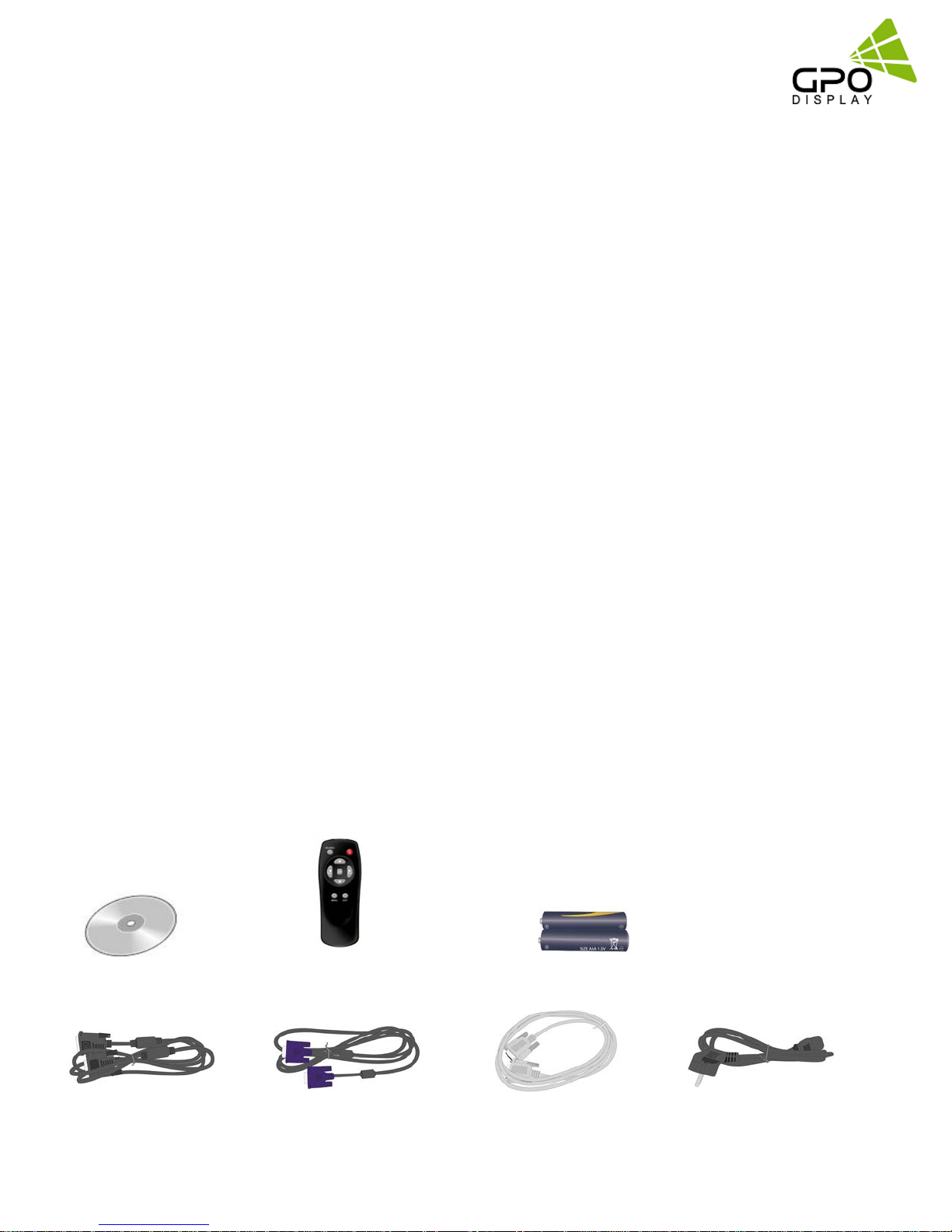
Accessories
User Guide Disc
DVI Cable
www.gpodisplay.com NSV-seri es Video w all
Remote
Controller
VGA Cable
Batteries (AAA x 2)
RS232C Cable Power Cable
5
Cautions For Consisting Series System
Environmental conditions for installation
Since the panel is very sensitive to physical impact, installation requires considerable caution.
Minimum clearance (4 inches) on top/bottom/right/left of video wall array must be secured for
proper ventilation. Installation must avoid airtight or nearly airtight places. Improper ventilation
causes malfunction and shortens product lifetime via rapid internal temperature increase. If NSV-
series displays must be installed in a poorly ventilated area, openings or fans must be provided to
keep the internal temperature between 32~95 ℉.
Please make sure to grounded (Earthing) AC power plugs and sockets.
Considering NSV-Series Max power consumption, check the main electric specification.
NSV-Series
Video wall
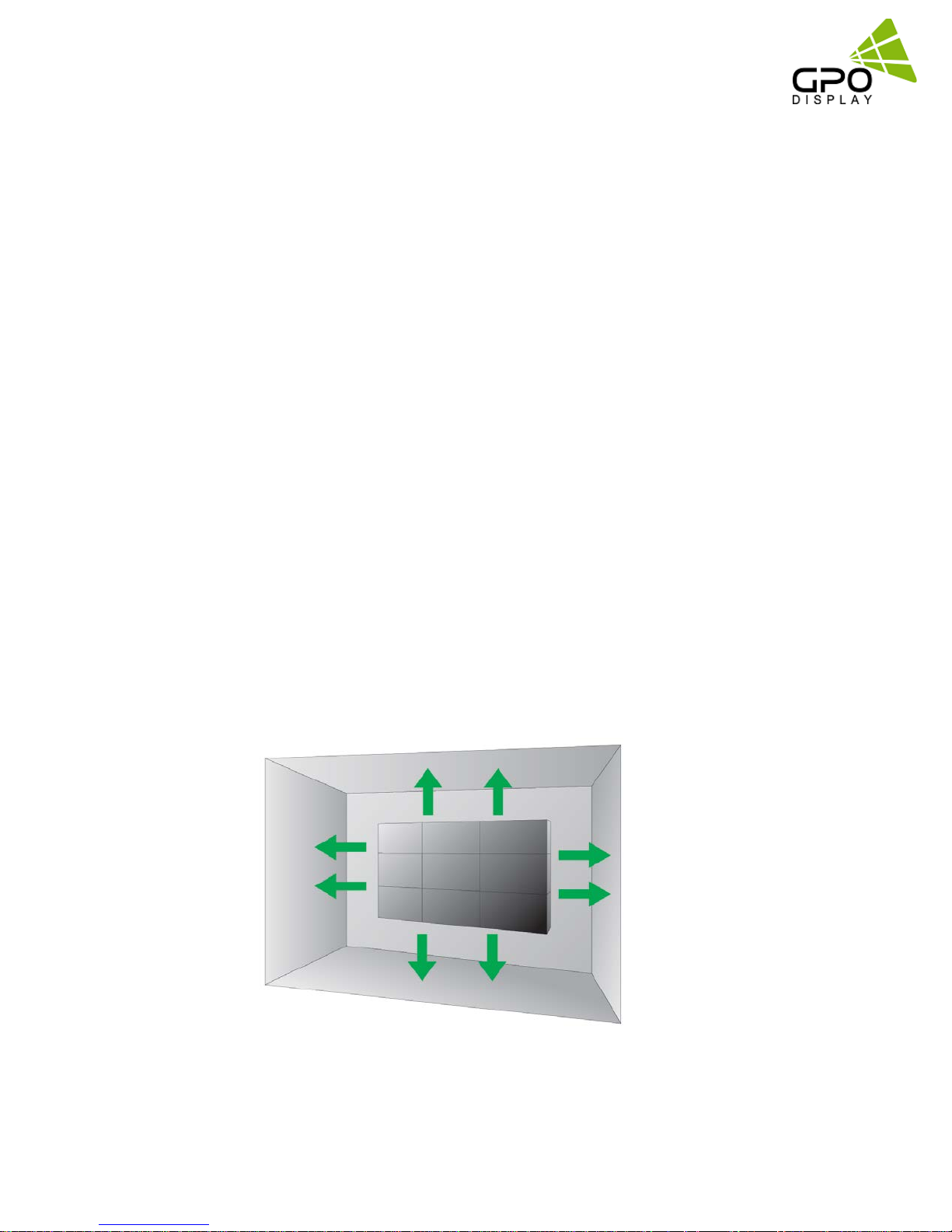
Clearance for Ventilation
When you install NSV-Series, make sure there is at least 4 inches clearance on all sides
(top/bottom/left/right) for effective ventilation and do not seal off the perimeter of NSV-Series
video wall arrays.
If NSV-series sets are installed at the locations with poor ventilation, the internal temperature can
rise rapidly, causing frequent malfunctions and rapid reduction of the product life.
4inch
4inch
4inch
4inch
Wall-Embedded NSV-Series Displays
In case of clearance <4 inches on each side of the display wall, make sure cooling fans are in place
at the upper part of the array to maintain internal temperature within the recommended threshold.
www.gpodisplay.com NSV-seri es Video w all
6

Mounting on a wall surface
NSV-Series
Video wall
Please secure minimum clearance as shown in the picture for adequate ventilation and
technical service.
Ventilation space in front of NSV-Series displays must be furnished for heat dispersion. If the area
in front of NSV-Series displays must be sealed, there must be consideration for the heat dispersion
on the rear side of NSV-Series to compensate.
Precautions for installation
During installation, do not apply pressure to any surface of the panel. Damage to the panel may
result from external pressure or even minor impact to the panel. Physical and cosmetic damage to
displays is not covered under warranty.
0.1mm
www.gpodisplay.com NSV-seri es Video w all
7
NSV-Series
Video wall
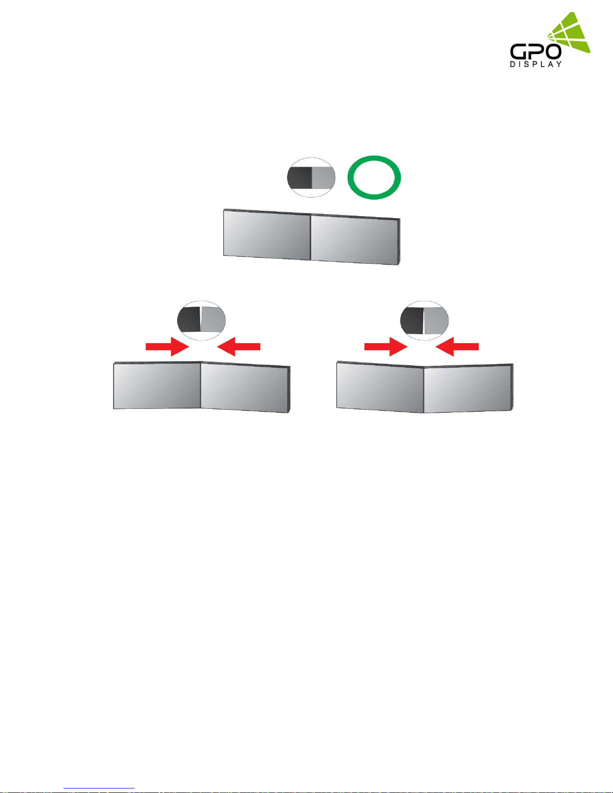
Please ensure alignment on the Z-axis for a level plane across adjacent panels (as shown in the
diagram below). If precautions are not heeded, GPO US will not accept responsibility for any
Failure due to such installation errors.
Do not apply excessive external pressure to panels during installation.
There is no warranty coverage for any damage arising from external
pressure/impact.
Do not cover fan ventilation holes
Carefully install NSV-Series not to cover the fan air holes with any structural object.
If the holes are covered with anything, the inner temperature can be raised rapidly and it
can cause malfunction.
www.gpodisplay.com NSV-seri es Video w all
8
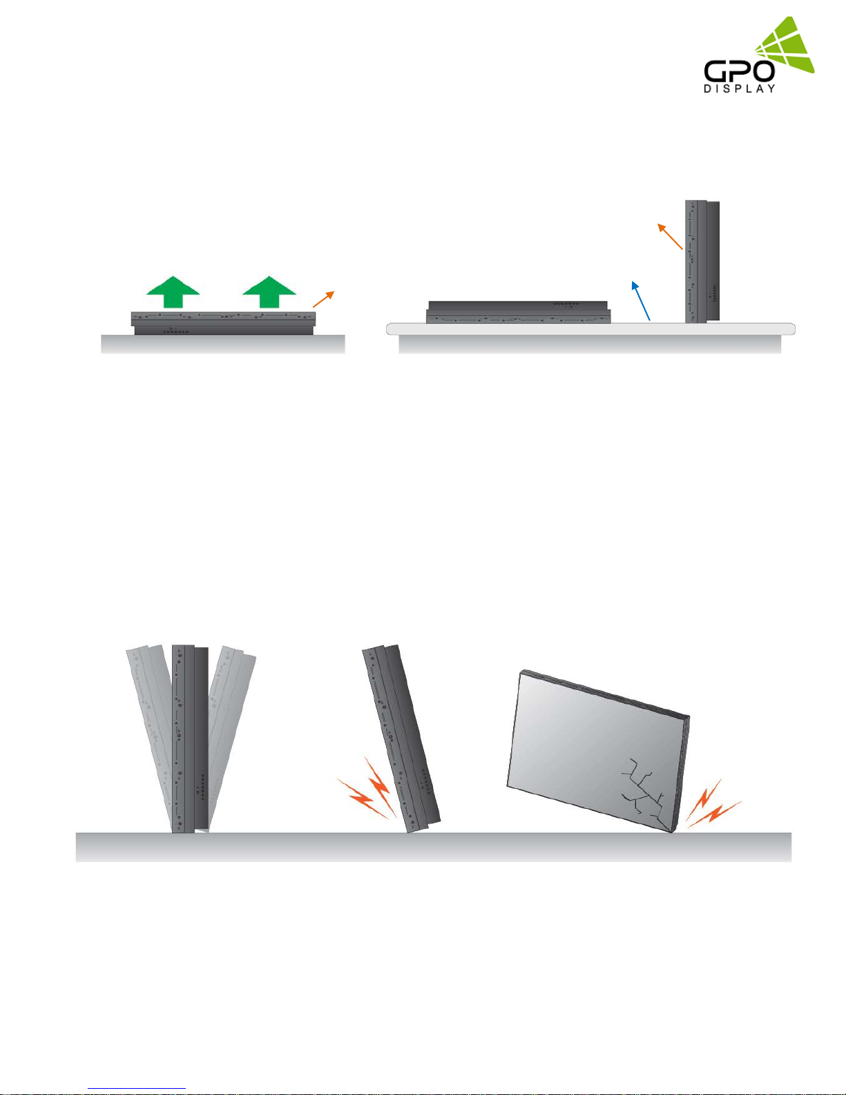
Please retain the following instructions for panel protection
This product can be damaged even with minor impact to sensitive areas.
Please keep following instructions for future reference when carrying or storing the products.
NSV-Series
Video wall
Panel
Cushion
If you need to lay down LCD
in a panel face-up position,
please be cautious and
avoid falling objects on the
surface of the LCD.
If you need to stand LCD
upright, you must use
handles on the rear and
pull/raise upward slowly so
that the LCD panel does
not touch the ground or
floor.
Panel
If you need to lay the LCD
in a face-down position,
please use shock-absorbing
pads under the LCD panel
surface.
Handle with Caution
Shock/Impact on the display’s sides will result in internal circuit damage.
The edges and surface of the panel are fragile. Use shock-absorbing pads or rugs when
laying the product down.
Please do not allow the LCD
to stand upright without a
technician holding it
upright. It may fall or slip
be broken or damaged.
Keep hands on the LCD
when it is in this position.
www.gpodisplay.com NSV-seri es Video w all
Do not lean the LCD on a
bezel edge as shown above.
This may result in damage
to the bottom bezel of the
LCD.
9
Do not lean the LCD toward
a bezel corner. This may
lead to panel damage.
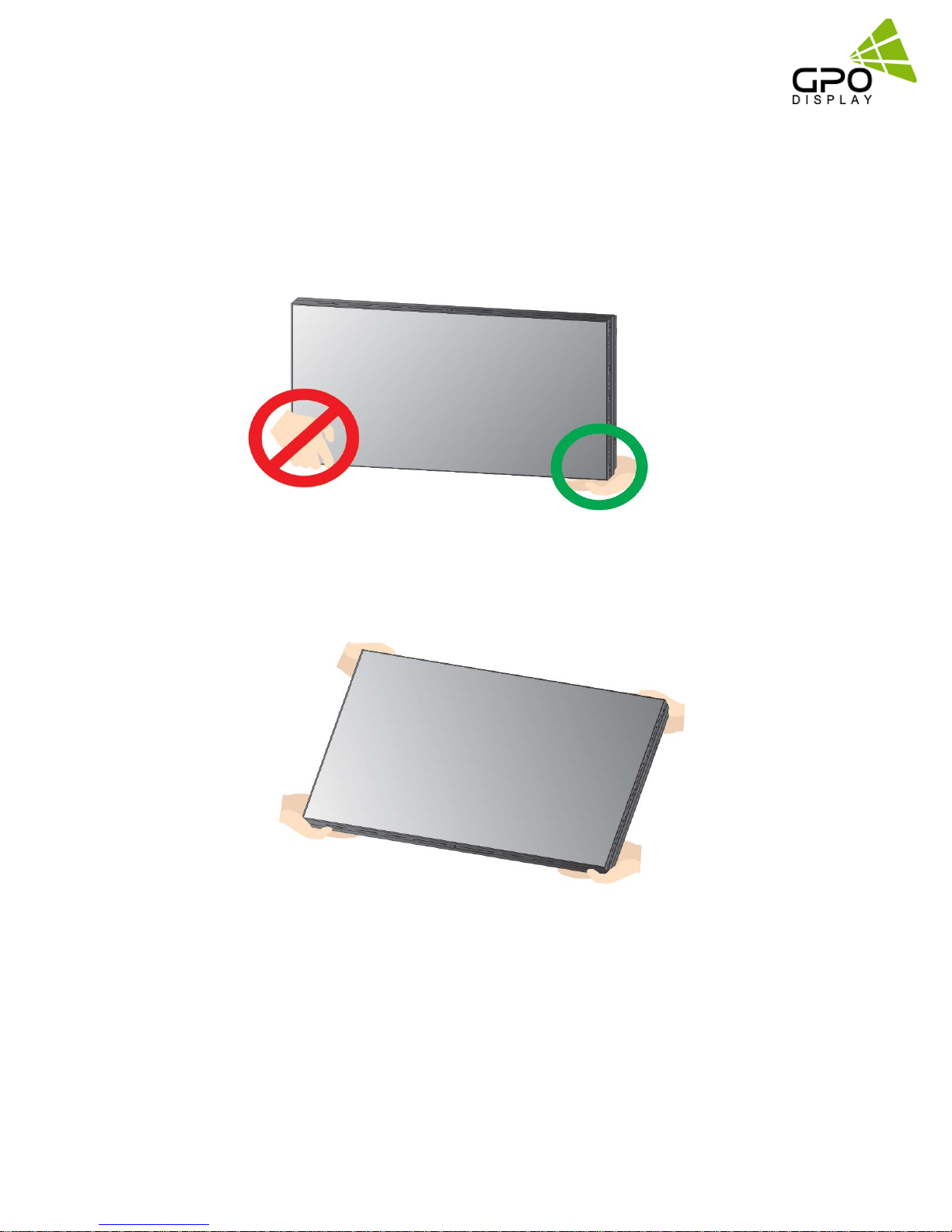
How to carry the product
At least two people are required to carry the display. W hen carrying the product
upright, please hold the handles on the rear as well as the bottom of the display
simultaneously for stability.
NSV-Series
Video wall
When carrying the product with the panel positioned upwards as shown below,
please hold as shown in the diagram.
Application information
If static images are displayed on the screen for extended periods of time, image retention
(burn-in) can result.
Please retain the following instructions to optimize the lifetime and functions of the product.
www.gpodisplay.com NSV-seri es Video w all
10
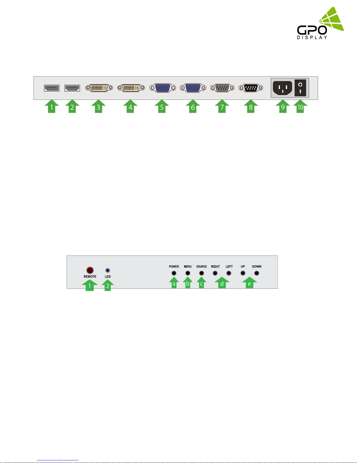
Mechanical Layout
1. DisplayPort Input
2. HDMI Input
3. DVI Input
4. DVI Output (DisplayPort, HDMI Output)
5. D-Sub Input
6. D-Sub Output
7. RS232 Input
8. RS 232 Output
9. AC Power In (100V ~ 240V)
10. AC Power Switch
NSV-Series
Video wall
1. IR Receiver
Aim the remote controller towards this spot on the LCD Display.
2. LED indicator
Indicates LCD Power Status (On : BLUE / Off : RED)
3. OSD KEY Input (Power / Menu / Source / Left / Right / Up / Down)
a) Power : Turns the LCD Display On/ Off.
b) Menu : Displays the main On-Screen menu.
c) Source : Select Input Source
d) Left / Right : Moves from one menu item to another horizontally or adjusts selected menu
values.
e) Up/Down : Moves from one menu item to another vertically or adjusts selected menu
values.
www.gpodisplay.com NSV-seri es Video w all
11
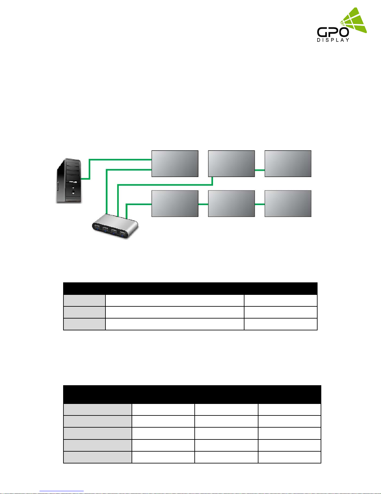
Connections
DVI and HDMI distributor instructions
In the event that a DVI or HDMI signal distributor/distribution amplifier
does not support EDID, first connect the cables to the input of the master
set (monitor) and then connect the cable from the output of the master
(monitor) to the distributor/splitter to the input of the slave set (Monitors)
as shown below:
NSV-Series
Video wall
*Input
Output
Input
Input
PC
*Note: “Input” and “Output” refers to whether the
Distribution Amplifier
•For use HDMI signal, use an HDMI-to-DVI cable between HDMI signal source and master set.
cable is connected to the display’s input or output
•Daisy Chain Connection Limit
Input Max Timing Daisy Chain
DVI 1920 X 1080
VGA 1920 X 1080
RS-232
•Image quality cannot be guaranteed when daisy chain connection limit is exceeded.
N/A 12 Displays
•Input Signal Distributor requirement
(assumes use of a 1in/4out signal distributor):
3 Displays
3 Displays
Connected
Sets
1~4
5~9
10~17
18~25
26~33
www.gpodisplay.com NSV-seri es Video w all
DVI VGA RS-232
0 0
1 1 0
2 2 1
3
4
12
3
4 3
0
2

Cable Connections (DVI)
NSV-Series
Video wall
Cable Connections (HDMI)
Cable Connections (DisplayPort)
www.gpodisplay.com NSV-seri es Video w all
13
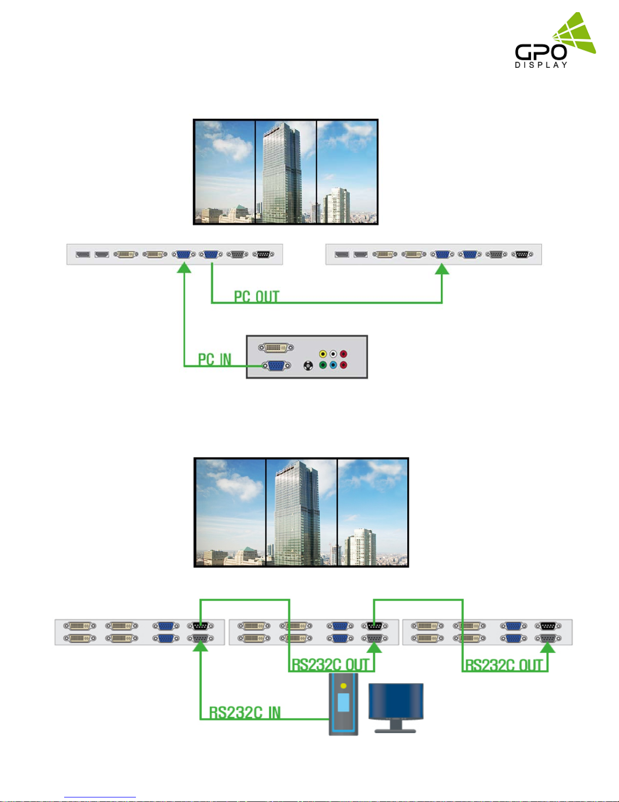
Cable Connections (VGA)
NSV-Series
Video wall
Cable Connections (RS232)
www.gpodisplay.com NSV-seri es Video w all
14
 Loading...