

GPO Display Video Walls - Commercial Monitors - Digital Signage - Visual Solutions www.gpodisplay.com
Installation Manual
[HLM Mount]
(Ver 1.0)
1

GPO Display Video Walls - Commercial Monitors - Digital Signage - Visual Solutions www.gpodisplay.com
WARNING !
Severe personal injury and property damage can result from improper installation or
assembly. Read the following warnings before beginning
Do not use this product for any purpose not explicitly specified by GPO Display. Improper installation may cause property
damage or personal injury. If you do not understand these directions, or have doubts about the safety of the installation,
contact GPO Display tech support or call a qualified contractor. GPO Display is not liable for damage or injury caused by
incorrect mounting, assembly, or use.
If mounting to wood wall studs, make sure that mounting screws are anchored into the center of the studs. Use of an "edge
to edge" stud finder is highly recommended.
Tighten screws firmly, but do not overtighten. Overtightening can damage or warp the items, greatly reducing their holding
power and negatively affecting display alignment.
This product is intended for indoor use only. Use of this product outdoors could lead to product failure and personal injury
For walls made of other materials, such as hollow bricks, please consult your installer and/or specialist
2

GPO Display Video Walls - Commercial Monitors - Digital Signage - Visual Solutions www.gpodisplay.com
Chapter 1 Precautions
To ensure safety, please read this manual carefully prior to installation and follow the instructions
herein. Store this installation guide in a secure place for future reference.
The video wall must be installed on a flat and level surface which is strong enough to bear its weight.
Make sure mounting brackets are tightened and secured on the wall
The Liquid Crystal Display (LCD) panel of the display has a very thin protective layer of coating which is susceptible to
marking or scratching, and cracking if struck or pressured. Please cover and protect the displays if there is construction
or other work being conducted at the installation site.
Transport and handle displays by holding the handles on the back of the display. Do not touch the LCD panel surface
directly to avoid possible scratches and backlight leakage
Leave a slight (≥0.5mm) gap between displays in order to protect your LCD screens from the damage through the direct
transfer of weight.
3
GPO Display Video Walls - Commercial Monitors - Digital Signage - Visual Solutions www.gpodisplay.com
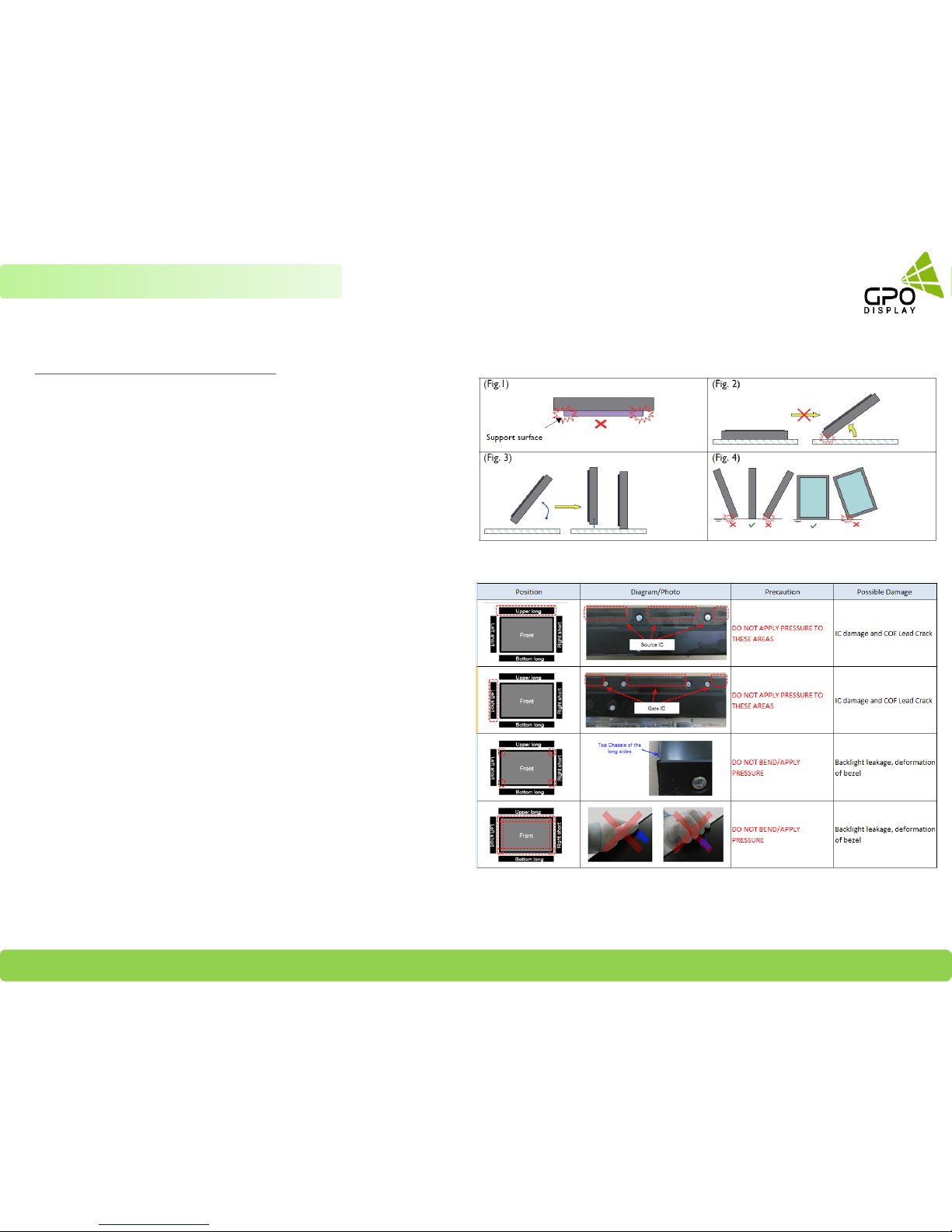
Notes on handling/transporting displays
LCD video wall monitors have limited mechanical strength. To prevent
performance failure caused by line defects, front bezel bending, panel
scratch/breakage, light leakage, etc., displays must be handled with care.
Always have at least two (2) adults supporting the display when
moving/carrying.
Retain the original shipping box and packaging in storage for use in the
future, when you may need to transport the product.
When placing the display face (panel side) down:
Prepare a flat, level, horizontal surface that is larger than the
display and spread a thick protective sheet/foam on it. (Fig. 1) –
Lay the display down gently and horizontally.
When you want to place the display in an upright position:
Lift the display up horizontally by holding the two (2) handles at the
top/rear with one hand per person and supporting the bottom bezel
with the remaining hand. Do not allow the display to rest/put
weight on bezel edges and corners (Fig. 2)
Be careful not to scratch any parts of the display when placing the
display upright. (Fig. 3)
Stand the display vertically to make sure the its weight spread
evenly throughout the bottom bezel. Do not rest on corners or lean
forward/back. (Fig.4)
4
Chapter 1 Precautions
GPO Display Video Walls - Commercial Monitors - Digital Signage - Visual Solutions www.gpodisplay.com
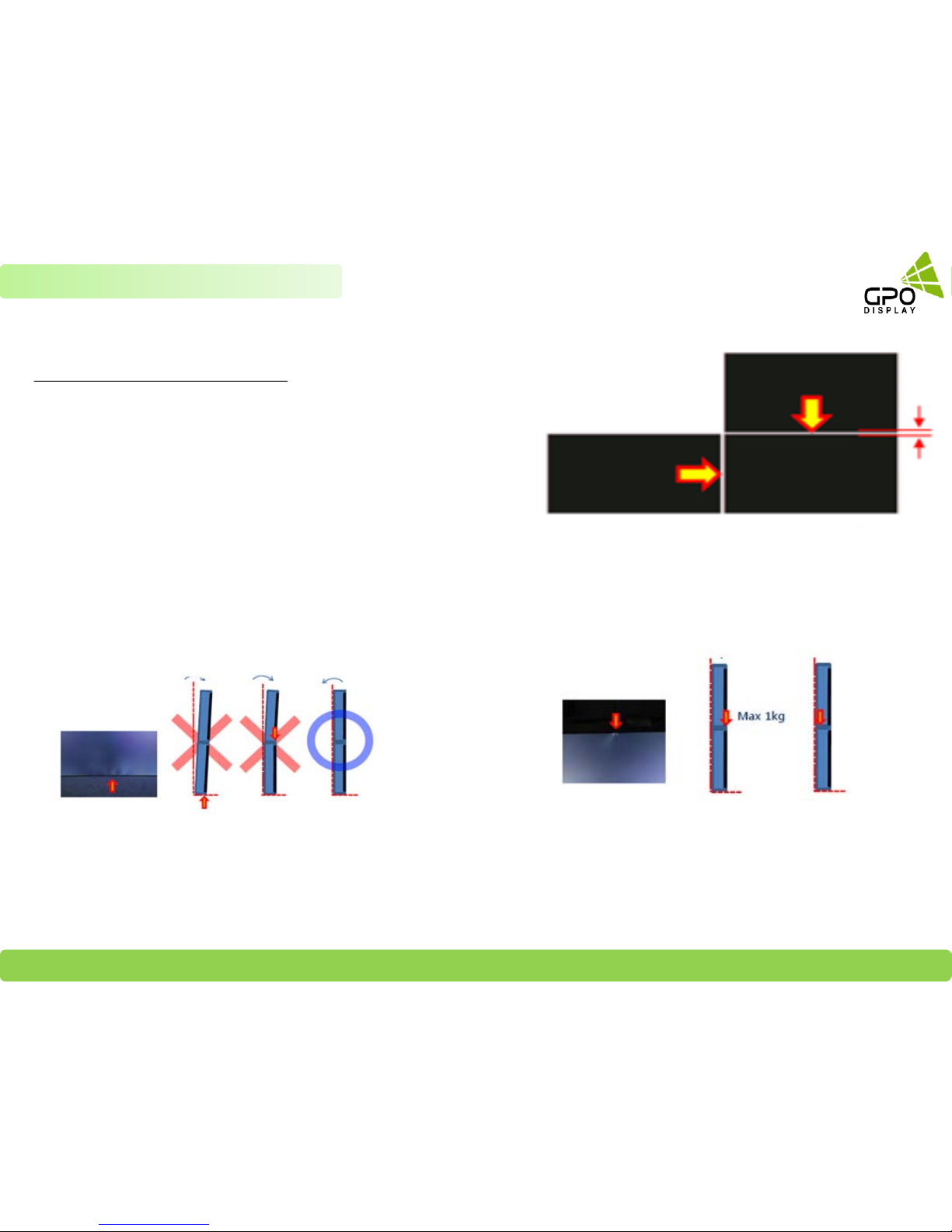
A minor gap between monitors is required
High temperatures can cause slight expansion of panels. If there is no space
between panels, damage may occur as a result of pressure resulting from the
expansion of adjacent panels into one another. Please ensure that there is a
≥ 0.5mm gap between the displays. This can easily be checked by sliding a standard
business card between the gap (if there is no resistance, the gap is sufficient)
*Recommended gap
between displays: ≥ 0.5mm
Do not tilt displays in a manner that would result in
pressure on the panel edges. If backlight leakage (as
shown below) is evident, this is a sign of excessive
pressure and adjustment to the alignment of the array
must take place.
If more than 1kg of weight is applied to the top bezel of a panel (as
illustrated to the right), backlight leakage will result. This is a sign that
the panel alignment/angle must be adjusted or other countermeasures
must be applied.
5
Chapter 1 Precautions
GPO Display Video Walls - Commercial Monitors - Digital Signage - Visual Solutions www.gpodisplay.com
Best practices for maintaining long-term quality
Keep temperature within 32°F ~ 104°F (Mandatory)
Follow Ventilation requirements
Keep panel usage under 20 hours per day in order to extend the stability and performance of the panel to longer than what is shown on the product
specification table.
Avoid displaying static images for prolonged periods of time.
Avoid content with significant brightness differences.
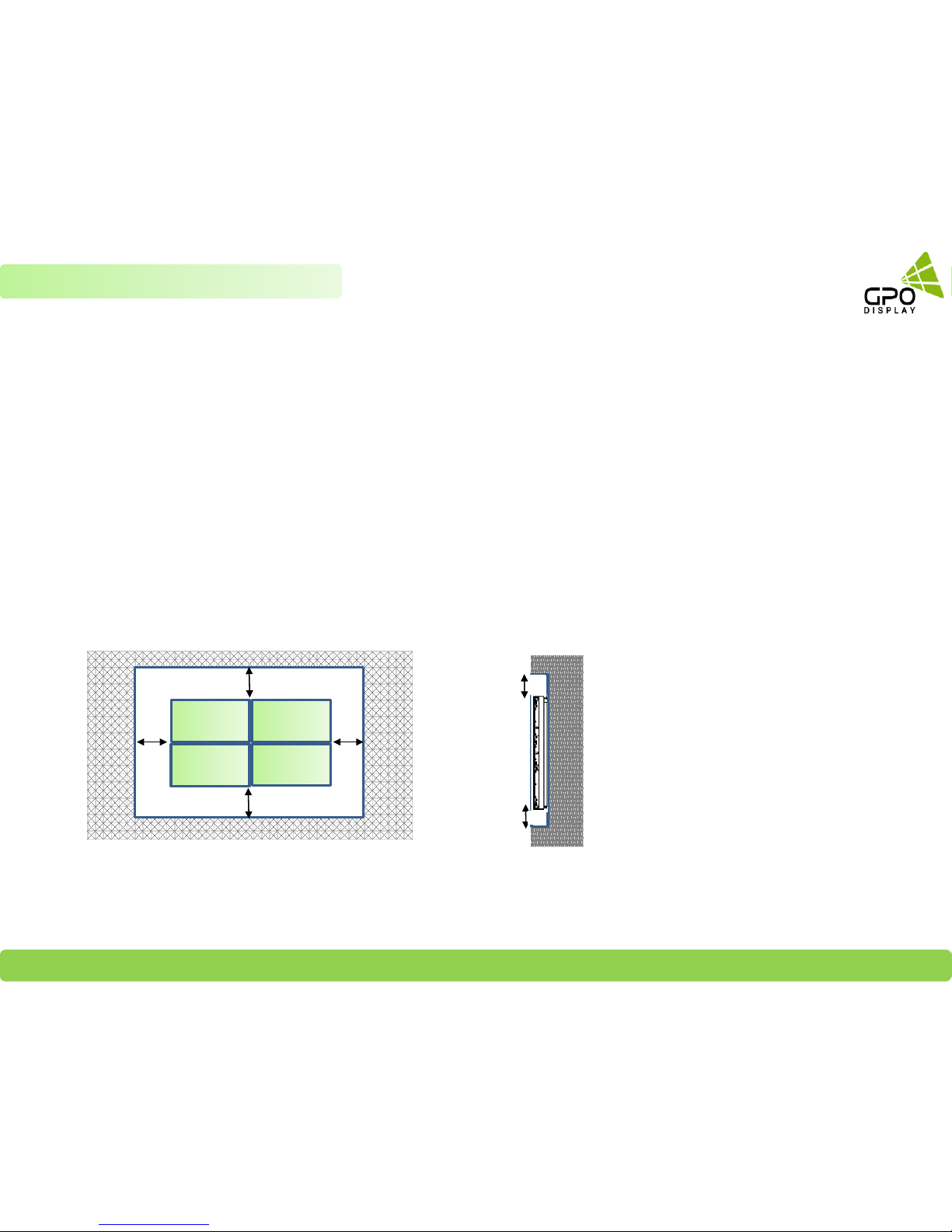
Dimensions below are minimum required for proper ventilation and movement of displays within H-Mount structure
3”
2”
* Note:
Ventilation space must not be covered or closed off at the
front of the opening. If for some reason the opening
needs to be covered, other means of ventilation will need
to be incorporated into the design. Contact GPO Display
for design review and recommendations.
6
Chapter 1 Precautions
•Clearance Spec: 3.5” (Left/Right), 3” (Top), 2” (Bottom)
3”
2”
3.5”
3.5”

GPO Display Video Walls - Commercial Monitors - Digital Signage - Visual Solutions www.gpodisplay.com
Structure for the installation
The structural design and construction for the display installation is the customer’s or its installer’s responsibility. GPO Display does not take
any responsibility on design or construction of installations. The minimum requirements for space, strength of the structure, electronic, heat
dissipation and environmental condition is described in this manual. If any further information or support is needed from GPO Display, please
contact us in advance to ensure ample time for support. We will be glad to help with any recommendations or information.
Call 510-659-9855 x1 or e-mail support@gpodisplay.com.
Power Requirements
Please refer to the specifications for power consumption of displays to be installed. Do not plug more than two units into a given receptacle
(example: all displays in 2x2 should not be plugged into quad receptacle. Using more than 70% of current on the AC circuit is strongly
discouraged. Clean AC power is required for “noiseless” screen images. Avoid damages inflicted by power glitches or surges- either a power
conditioner or surge protector is recommended. Contact your electric power specialist for consultation.
Heat Dissipation Requirements
The range of LCD operational conditions are:
Temperature: 32°F ~104°F Humidity : 20 ~ 80%
-Consult with the display user manual for BTU ratings.
7
Chapter 2 Preparations
GPO Display Wall Mounts
Model Dimension (W x H x D, inch) Weight
ZLM46T 40.24 x 22.7 x 2.13 25lbs
HLM46TE 40.16 x 22.63 x 2.13 25lbs
HLM49T 42.42 x 23.93 x 2.13 30lbs
HLM49TE 42.35 x 23.86 x 2.13 30lbs
HLM55T 47.76 x 26.93 x 2.13 37lbs
HLM55TE 47.7 x 26.86 x 2.13 37lbs
GDSVW775 21.25 x 21.25 x 3.9 to 14.02" 28lbs
Product Description
Verify wall mount model name and check dimensions and weight.
GPO Display Video Walls - Commercial Monitors - Digital Signage - Visual Solutions www.gpodisplay.com
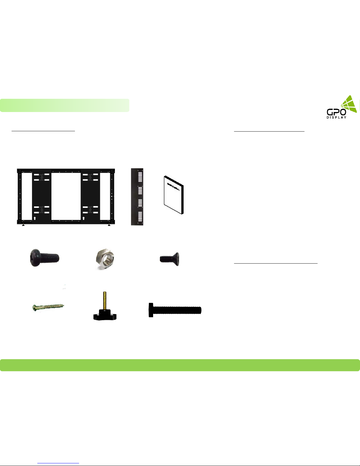
Components for Installation
Open all packages and take stock of the contents. Make sure all materials are present
and there is no visible damage.
M8 NUT
SCREW (FH M 4*8L)
(for Side Covers)
Side Cover (Trim)
Wall Mount
USER MANUAL
SCREW (BH T 4*20L)
BOLT (M8*20L)
Suggested Tools for Installation
Laptop with USB to RS-232 adapter
Drill w/ metal, wood, and mortar bits
Phillips head screwdriver
Tape Measure
Level
Socket Set
Wrench set
Shims (metal or wooden for alignment adjustment
when a wall is uneven)
Cable ties for final cable dressing
Screen cleaner and lint-free cloth for final cleanup
* This is a bare minimum list – review statement of
work to determine all tools needed.
Supporting Documents and Software
Display Manual
Serial Command Protocol and video wall control
program (varies by video wall series)
ACR Manual (if applicable)
Wall Mount Drawing
8
Chapter 2 Preparations
Y-Knob
Z-Bolt
GPO Display Video Walls - Commercial Monitors - Digital Signage - Visual Solutions www.gpodisplay.com
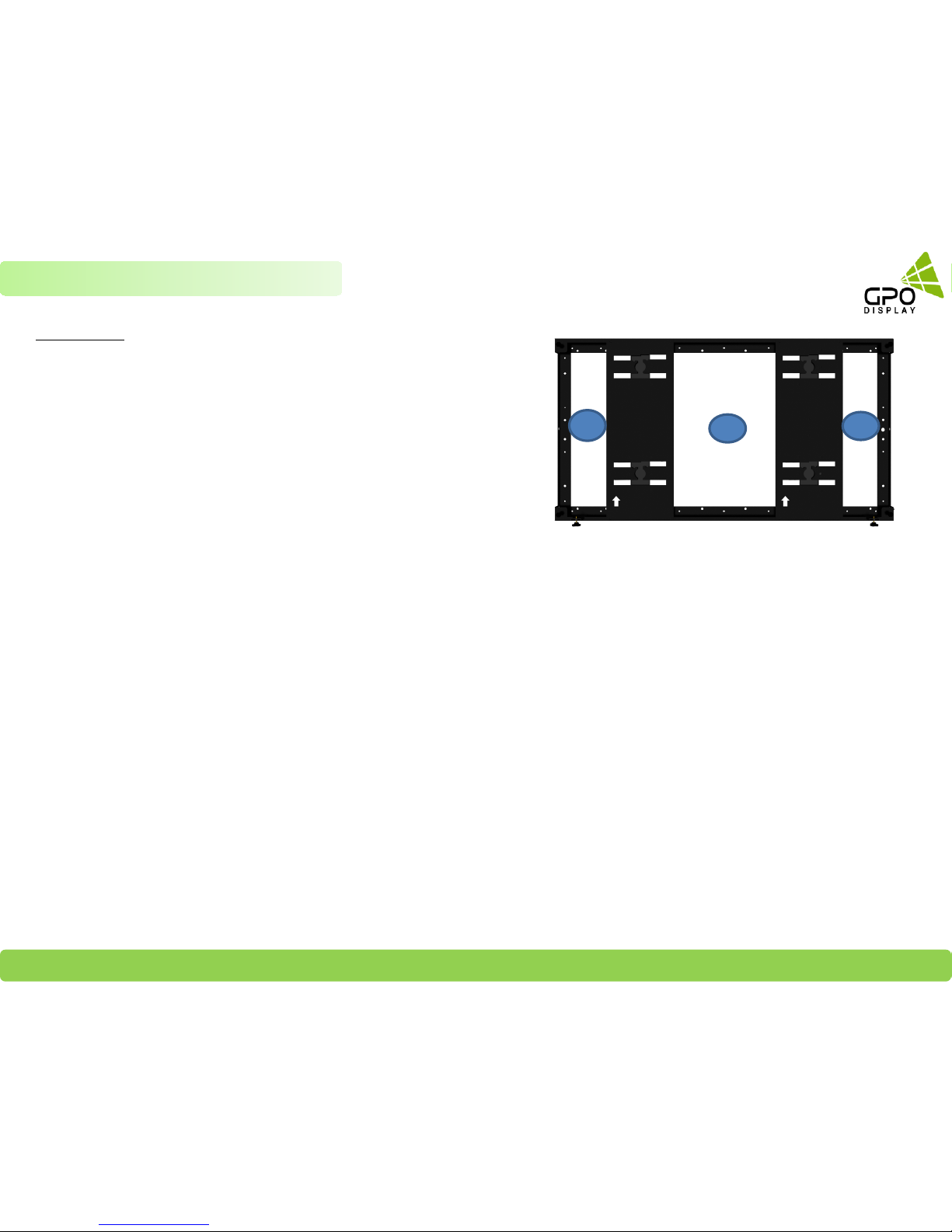
See the image to the right for recommended position of recessed power
outlets (B is the ideal location for power outlets for 46-49” models).
Outlets which are level with the surrounding wall surface may lead to
obstruction of the side-to-side movement of displays within the mount
structure. Position A is the ideal position for any third-party devices
(receivers, decoders, media players, etc.). There is ~2” depth to work with
on both sides (positions A & C).
Recommend recessed power outlet positions: B : 46” & 49”,
A or C : 55”
Recommend Receiver / Decoder / Media Players Positions:
A or C .
9
Positioning
Chapter 2 Preparations
[HLM46T & HLM46TE Device placement]
A
C
B
A & C zones: 2.35 (W) x 15 (H) x 2.2”(Depth) for
Third party placement. The area outlined in red (6” x
15”) is available if the device is under 1.8” in depth
B zone: 10 x 15 x 2.2” (Depth) for Power Outlet
[HLM55T & HLM55TE Device placement]
A & C zone: 5 x 15 x 2.2” (Depth) for Third party
placement. The area outlined in red (8” x 15”) is
available if the device is under 1.8” in depth
B zone: 10 x 15 x 2.2” (Depth) for Power Outlet
[HLM49T & HLM49TE Device placement]
A & C zone: 3.5 x 15 x 2.2” (Depth) for Third party
placement. The area outlined in red (6” x 15”) is
available if the device is under 1.8” in depth
B zone: 10 x 15 x 2.2” (Depth) for Power Outlet
NOTE: See detailed drawings of each mount on
pg. 36-38
GPO Display Video Walls - Commercial Monitors - Digital Signage - Visual Solutions www.gpodisplay.com
10
Chapter 2 Preparations
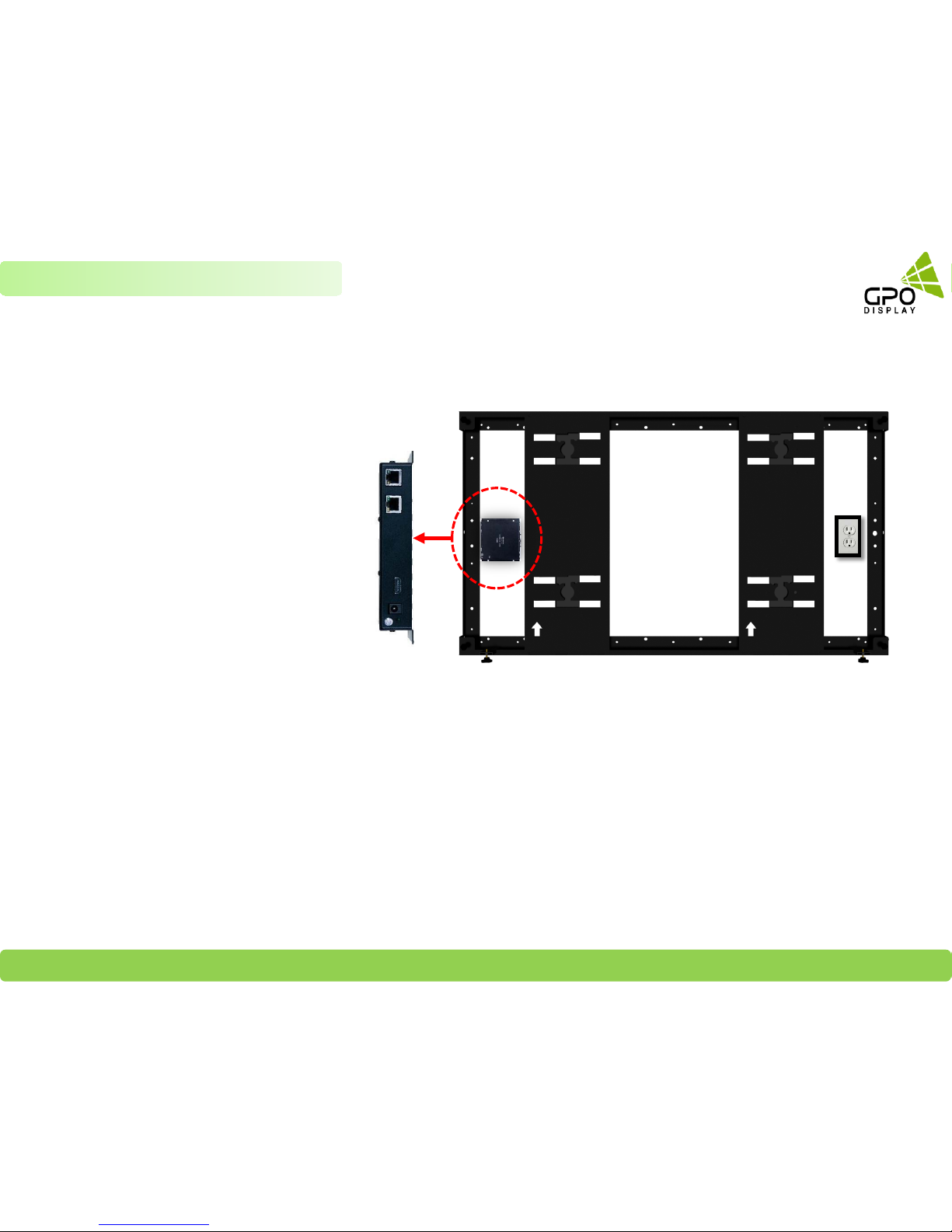
[Tip. Third party player placement]
Device inputs/output terminals should
be positioned facing to the left, as
shown in the image to the right.
Devices (Receiver/decoder, Distribution Amplifier, etc.)
GPO Display Video Walls - Commercial Monitors - Digital Signage - Visual Solutions www.gpodisplay.com
11
Chapter 2 Preparations: Wall Mounting
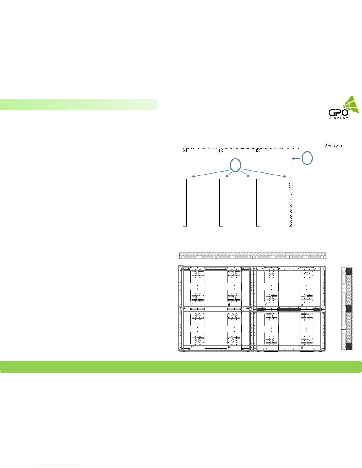
Reinforcement Frame Installation (if applicable)
A: Wall
B: Secure wooden 2x4 or 2x6, or metal framing (4 X 1 T)
to the wall as shown in the drawing to the right.
A
B
1. Construct the reinforcement frame to match
specifications set forth by GPO Display
2. Continue constructing the reinforcement frame, adding
cross bar supports where necessary
3. Affix Z-Shift wall mounts to reinforcement frame as
shown in the image to the right. Be sure to bolt the Z-Shift
mounts to one another using the M8 bolts provided by GPO
Display. Be sure to use uniform torque when doing so.
GPO Display Video Walls - Commercial Monitors - Digital Signage - Visual Solutions www.gpodisplay.com
12
Plywood-Backed/Flat wall surface Installation (if applicable)
1. Affix ¾” plywood to the wall. Power outlets must be recessed.
Outlets which are level with the surrounding wall surface may lead
to obstruction of the side-to-side movement of the screens within
the Z-Shift mount structure.
When plywood backing is
used, ensure that there are
holes of sufficient size to
run all necessary cabling
.
3. Assemble the mounts (affix to one another using
interconnecting M8 bolts) and ensure that they are level, as
instructed previously in this manual.
2. Affix H-mounts in the manner shown in the image on the right,
following the steps set forth in previous pages of this manual
.
Chapter 2 Preparations: Wall Mounting

GPO Display Video Walls - Commercial Monitors - Digital Signage - Visual Solutions www.gpodisplay.com
To install GPO Display’s displays in video wall configuration, please read the installation directions carefully before
installation is performed. These monitors can be installed for single display ”standalone” operation, in a single row, or in
multiple rows. The highest Display Sequence number is 99. Contact GPO Display for arrays comprised of more than 99
displays. A 3x3 array will be used as an example in the following pages. Contact GPO Display if you are unsure about how to
apply these instructions and concepts to other video wall array configurations.
STEP 1
Verify that installation location is ready (power, network, wall reinforced, adequate ventilation, coax cable if being
installed)
Verify all necessary tools are ready to use.
Open all packages and lay everything out. Make sure all materials are present and there is no visible damage.
Note: RS-232 Cables must be daisy-chained for ease of service/firmware updating
Preparations
13
Chapter 3 Mounts Installation

GPO Display Video Walls - Commercial Monitors - Digital Signage - Visual Solutions www.gpodisplay.com
Install Wall Mounts (3x3 example)
14
STEP 2
Chapter 3 Mounts Installation
Affix first H-Mount to Wall or Wall Reinforcement frame with lag
screws (M4*20L). Measure carefully to ensure that the bracket
is located at the bottom/center of the array outline and that the
mount is level.
Use M8 interconnecting bolts & corresponding nuts to connect
the second mount and third mount to the first mount. Next,
affix second mount to Wall or Wall Reinforcement frame with
lag screws (M4*20L). Ensure that these mounts are level.
Tips for 2x2 or 3x3 video wall arrays
If your array is a 2x2 array (or 2x1, or 1x2), you may pre-assemble
mounts. For example, this means that you may use the M8
interconnecting bolts to construct a 2x2 frame prior to hanging the
mounts on the wall using The lag screws. This will help save time for
these smaller arrays. The mounts shown to the right are an older model
but the concept still applies to the current version of H-Mounts.
In a 3x3, you may assemble rows on the ground then attach to wall.
*Note: Floor surface must be level/even when connecting mounts.
Must connect mounts using M8 Bolts and nuts at all interconnection
positions (Long side: 14 positions, Short Side: 5 Positions)
1
3
12
3
12

GPO Display Video Walls - Commercial Monitors - Digital Signage - Visual Solutions www.gpodisplay.com
Install Wall Mounts (3x3 example)
15
STEP 2
Chapter 3 Mounts Installation
Use M8 interconnecting bolts & corresponding nuts to connect the
fifth and sixth mount to adjacent mounts in the positions outlined
in dotted red lines. Next, affix this fifth mount to Wall or Wall
Reinforcement frame with lag screws (M4*20L). Check level again.
Use M8 interconnecting bolts & corresponding nuts to connect the
fourth mount to the first mount. Next, affix fourth mount to Wall or
Wall Reinforcement frame with lag screws (M4*20L). Check with
level again.
3
12
4
3
12
4
5
6
For 3x3 arrays, you may assemble rows of mounts on the
floor* prior to attaching them to the wall. See example of
second row to the right
*Note: Floor surface must be level/even when connecting
mounts.
6
45
Tips for 2x2 or 3x3 video wall arrays

GPO Display Video Walls - Commercial Monitors - Digital Signage - Visual Solutions www.gpodisplay.com
Install Wall Mounts (3x3 example)
16
STEP 2
Chapter 3 Mounts Installation
Use M8 interconnecting bolts & corresponding nuts to connect the
eighth and ninth mount to adjacent mounts. Next, affix this 8
th~9th
mount to Wall or Wall Reinforcement frame with lag screws (M4*20L).
Check level again.
For 3x3 arrays, you may assemble rows of mounts on the
ground prior to attaching them to the wall. See example of
third (top) and final row to the right
*Note: Floor surface must be level/even when connecting
mounts.
9
78
Tip for 2x2 or 3x3 video wall arrays
3
12
4
5
6
7
8
9
Use M8 interconnecting bolts & corresponding nuts to connect the
seventh mount to the forth mount. Next, affix 5
th~6th
mount to Wall or
Wall Reinforcement frame with lag screws (M4*20L). Check level again.
3
12
4
5
6
7

GPO Display Video Walls - Commercial Monitors - Digital Signage - Visual Solutions www.gpodisplay.com
Install adjustment bolts/knobs
17
STEP 3
Chapter 3 Mounts Installation
Insert Z-Bolts into each mount (there are insertion positions at
each of the four corners). Make sure they are fully inserted.
Insert Y-Knobs into each mount (there are two insertion
positions located at the bottom left/right of the mount).
Turn Y-Knob clockwise until ~1mm of the bolt is visible stop the Y-
Adjustment plate. The image shown to the bottom/right shows the
Y-Knob inserted further than needed during initial installation. Make
sure that the end of the bolt does not protrude more than 1mm
above the Y-Adjustment plate prior to installation of the displays.
Further adjustments can take place once displays are installed.
Y-Knob
Z-Bolt
Y-Knob
Z-Bolt
Y-Adjustment Plate

GPO Display Video Walls - Commercial Monitors - Digital Signage - Visual Solutions www.gpodisplay.com
1. Organize cables using cable tie and cable tie mount =>
Cable tie must not be fastened so tight as to prevent future
movement/pulling of cables
18
Organize Cables and Devices
STEP 4
2. Recommended cable paths shown on the right
=> Position all cables before display is mounted
=> Locate the cable tie mounts in the center of the
mount structure (rather than the bottom or top
)
3. Locate/mount all devices before display is mounted
Chapter 3 Mounts Installation
Example shown above is 55”

GPO Display Video Walls - Commercial Monitors - Digital Signage - Visual Solutions www.gpodisplay.com
1. Carefully unpack the display, using only the handles at the rear of the panel to
lift it out of the cardboard box.
* Caution:
When carrying the panel within the bag, be sure that you are grasping the display
and not the bag only as the bag may tear, resulting in damage to the panel
2. Lay the back of the Set down on a table
(LCD panel facing upward)
3. Power the display on and check for a “no signal” message.
Assign the display’s Set ID using the remote controller provided in
the accessories box and make a note of this Set ID number. Power
the display off (See OSD interfaces on the right). For more detailed
information on this process, consult the display user manual.
19
Preparation of Display
STEP 1
Chapter 4 Display Mounting
[NSV / EN Series] [EK Series]
Note: Set ID’s are assigned prior to shipment.
Set ID’s are marked on the display box.

GPO Display Video Walls - Commercial Monitors - Digital Signage - Visual Solutions www.gpodisplay.com
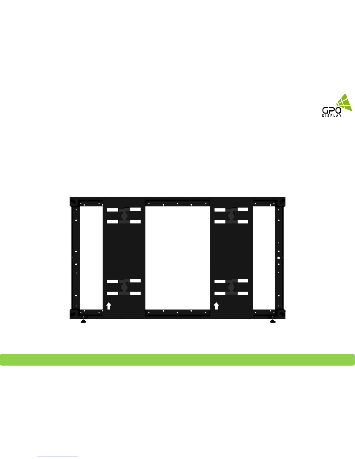
Before mounting the displays. Please review the H-Mount’s channel structure:
20
Mount overview
STEP 2
H-Mount Area Descriptions
Upper Service Channel Used for convenient dismounting when displays are in upper channel
Lower Service Channel Used for mounting and most dismounting cases
Opening
This is a safety mechanism used to alert technicians when the display is about to drop
into a lower channel (either from the upper channel or from the center channel)
Installation channel Used for convenient dismounting when displays are in lower channel
Resting Position This is where the display is seated when installation is complete
Lower
Service
Channel
Upper Service
Channel
Opening
Installation
Channel
Resting Position
Chapter 4 Display Mounting

GPO Display Video Walls - Commercial Monitors - Digital Signage - Visual Solutions www.gpodisplay.com
Each display features four pegs located on its rear side.
Each of these pegs has a round, button-shaped knob
which fits into the openings in the H-Mounts. When
hanging a display in an H-Mount, ensure that the display
is parallel to the H-Mount (not angled). This will help
ensure that all four pegs are inserted into each of the
four mount openings/insertion points.
21
Display Mounting (3x3 example)
STEP 3
Each display and its corresponding H-Mount has the
same width & height. When installing displays, note
that the service opening is positioned so that the
display outline will sit ~1.4” higher than the mount
outline when the pegs are aligned with the service
opening. Horizontal guide notches on the bottom
corners of the H-Mount frame help to guide the display
position during the mounting process, showing whether
the pegs are aligned with the openings/insertion points.
The bottom bezel of the display should align with the
horizontal notches during mounting.
*NOTE: Prior to installing displays, ensure cabling is
properly positioned, as shown on p. 18 of this manual.
Wall Mount
Display
Peg
Guide notch
Chapter 4 Display Mounting

GPO Display Video Walls - Commercial Monitors - Digital Signage - Visual Solutions www.gpodisplay.com
22
Display Mounting (3x3 example)
STEP 3
Begin mounting displays as described on p. 21 with the
bottom/right display, as shown above. Please note that the
numbers used in this mounting diagram DO NOT correspond
with SET IDs. After mounting display, connect cables and power
on. Make sure the that the input & output cables are connected
correctly- these are sometimes confused for one another. Check
the display for signal and then power off with remote controller.
Install a display directly above the previously mounted display. After
inserting the pegs in the opening, slowly & carefully ease the display down
until it comes to in the installation channel. Make sure that the display is
eased down into the installation channel evenly- if one side is dropped too
quickly, damage to the previously-installed display may occur.. Refer to p.
5 for more information on recommended gap between displays. Connect
cables and power cords.
Follow the same steps for the top/right display as were set forth for the
second display. Move all three displays to the right.
Set ID
#9
1
3
Set ID
#6
2
Set ID
#9
1
Set ID
#3
3
Set ID
#6
2
Set ID
#9
1
Set ID
#3
Mount & display order: Bottom to top
Alignment adjustment order: Top to bottom
Chapter 4 Display Mounting

GPO Display Video Walls - Commercial Monitors - Digital Signage - Visual Solutions www.gpodisplay.com
23
Display Mounting (3x3 example)
STEP 3
Shift displays to the right until they come into contact with the
right column of displays. Do so gently and be careful not to impact
the right column of displays with force.
Repeat the same steps taken for the right column of displays
with the center column of displays.
3
Set ID
#6
2
Set ID
#9
1
Set ID
#3
Set ID
#8
4
3
Set ID
#6
2
Set ID
#9
1
Set ID
#3
Set ID
#8
4
Set ID
#5
5
Set ID
#2
6
Chapter 4 Display Mounting
3
Set ID
#6
2
Set ID
#9
1
Set ID
#3
Set ID
#8
4
Set ID
#5
5
Set ID
#2
6
Set ID
#7
7
Set ID
#4
8
Set ID
#1
9
Repeat the same steps taken for the previous columns with
the left column of displays.

GPO Display Video Walls - Commercial Monitors - Digital Signage - Visual Solutions www.gpodisplay.com
Alignment: Z-Axis
Z-axis alignment can be adjusted by turning “Z-Bolts” at the rear of each corner of the display counter-clockwise.
This will push a given corner of a display outward from the wall, moving the corner of the display forward slightly.
24
Chapter 5 Alignment
Z-BOLT
Tip. Displays naturally tilt downward, meaning the top
protrudes slightly more than the bottom. In order to make Z-
Axis adjustments, push very gently with an open, gloved palm
on the top of the display and then engage the bottom Z-Bolts
by turning counter-clockwise.
STEP 1
Introducing alignment mechanisms

GPO Display Video Walls - Commercial Monitors - Digital Signage - Visual Solutions www.gpodisplay.com
Alignment: Y-Axis
Y-Axis alignment can be adjusted by turning the “Y-Knob” at the
bottom of the mount structure. A clockwise turn will raise the
bolt attached to the knob, which will raise one side of the display.
Conduct these adjustments in minor increments and exercise
caution when returning neighboring displays to their final,
installed position. Y-axis adjustments may lead to displays
“sitting” on top of displays below, causing excessive pressure on
bezels.
25
Chapter 5 Alignment
Case#1
Case#2
Y-Knob
STEP 1
Turn the outer Y-knobs (1 and 4) clockwise to move the
displays upward as needed to achieve Y-Axis alignment.
Turn the inner Y-knobs (2 and 3) clockwise to move the
displays upward as needed to achieve Y-Axis alignment.
1
2 3
4
1
2 3
4

GPO Display Video Walls - Commercial Monitors - Digital Signage - Visual Solutions www.gpodisplay.com
X-axis alignment must be carefully accounted for during the
installation process. To ensure proper alignment on the X-axis,
ensure that all mounts are in line with one another prior to
hanging displays. The application of side covers will lock displays
in line with the mounts on the X-axis, preventing any drift.
Alignment: X-Axis
26
Chapter 5 Alignment
Display
3.4”
Peg
3.4”

GPO Display Video Walls - Commercial Monitors - Digital Signage - Visual Solutions www.gpodisplay.com
27
Conducting Alignment
STEP 2
Move left column of displays to the left
Look over the wall for alignment issues from various angles.
Chapter 5 Alignment
Move center column of displays to centered position (resting
position)
3
Set ID
#6
2
Set ID
#9
1
Set ID
#3
Set ID
#8
4
Set ID
#5
5
Set ID
#2
6
Set ID
#7
7
Set ID
#4
8
Set ID
#1
9
3
Set ID
#6
2
Set ID
#9
1
Set ID
#3
Set ID
#8
4
Set ID
#5
5
Set ID
#2
6
Set ID
#7
7
Set ID
#4
8
Set ID
#1
9

GPO Display Video Walls - Commercial Monitors - Digital Signage - Visual Solutions www.gpodisplay.com
28
Alignment adjustments
STEP 6
3
6
9
7
4
1
8
5
2
3
6
9
7
4
1
8
5
2
1) Set #1 (marked 1 on right): Use Z-Bolt and adjust balance if needed
2) #1 : Using Y-Knob, raise both sides of display 1~2mm up if there is
no gap between bottom of #1 and #4
3) Slide #2 toward #1, checking Z-axis alignment. If alignment is poor,
adjust left Z-Bolts of #1 and right of Z-Bolts of #2 as needed.
Tip) Move #2 back to the left and compare its Z-bolts with the
backend of #1. The heads of #2’s Z-bolts should align with the back of
display #1. Slide #2 back toward
#1 (to the right) in its resting position. You may need to pull out on #2
slightly as you move it over to the right.
4) After making this adjustment, adjust #2’s Y- knobs to match level
with #1 (see p. 25 for more details on Y-Knob adjustments)
5) Follow the same steps on #3 with the directions reversed.
6) Move on to the next row of displays, substituting #4 for #1, #5 for
#2, #6 for #3, and so on for following row.
*Conducting Z-Axis adjustments prior to Y-Axis adjustments is
recommended.
Chapter 5 Alignment
Note: displays have been renumbered to show
recommended order of alignment adjustment s
3
6
9
7
4
1
8
5
2

GPO Display Video Walls - Commercial Monitors - Digital Signage - Visual Solutions www.gpodisplay.com
29
Finish
STEP 6
Affix side covers (shown outlined in red bottom/right) by screwing into
mounts. Use the FH M 4*8L screws provided.
Attach side cover by inserting screws into the outer sides of H-Mounts
on the perimeter of the array.
SCREW (FH M 4*8L)
(for Side Covers)
Side Cover
Chapter 5 Alignment

GPO Display Video Walls - Commercial Monitors - Digital Signage - Visual Solutions www.gpodisplay.com
Note: Remove side covers prior to attempting dismounting of displays. Ensure that Y-Knobs and Z-Bolts
are retracted for ease of movement.
30
Chapter 6 Display Dismounting
Example: Dismounting Set ID #9
• Start from the bottom-right display (in the case of 3x3, Set ID #9).
• Release Y-knobs of #’s 7 and 8 by turning counter-clockwise.
• Slide #’s 7 and 8 to the left.
• Follow the same steps on #’s 4 and 5
• Follow the same steps on #’s 1 and 2.
• Move Set #3 into the Upper Service Channel.
• Move Set #6 into the Lower Service Channel.
• Remove cabling from Set #9.
• Carefully lift #9 up ~1.4” so that the pegs align with the opening (bottom of Set #9 will align with corner guidelines on
mount).
• Gently pull #9 outward.
• From here, dismounting the remaining displays becomes easier. You may now dismount Sets 6 or 8.
SET
ID# 4
SET
ID# 2
SET
ID# 3
SET
ID# 1
SET
ID# 5
SET
ID# 6
SET
ID# 9
SET
ID# 8
SET
ID# 7

GPO Display Video Walls - Commercial Monitors - Digital Signage - Visual Solutions www.gpodisplay.com
Precaution for Cables Connection of GPO Display’s Video Wall
31
Digital noise may appear due to poor quality DVI cabling. If the video signal needs be delivered from a distance, electric noise must be accounted for. If the
distance is great or there is a serious noise issue, an optical fiber extender system is recommend over CAT-5/6 extension.
Daisy-chaining can be initiated from any unit. There is no terminator at the end of the unit. It is strongly recommended that installers/customers record the
chaining diagram as it is crucial for diagnosis of issues, should they arise.
Some installation sites have a high level of Electric Noise which may appear onscreen, especially with DVI.
DVI, HDMI and DisplayPort are HDCP-compliant.
Signal-looping specifications
Video signals should be boosted by using a distribution amplifier when more than four (4) units are connected via DVI (NSV & EN-series) or nine (9) units are
connected via HDMI (EK-series) -> See tables below
Chapter 7 Cabling Setup
Input Max Timing Daisy Chain
DVI 1920 X 1080 4 units
VGA 1920 X 1080 4 units
RS-232 N/A 20 units
Daisy Chain Connection Limit
•Image quality cannot be guaranteed when daisy chain connection limit is exceeded.
HDMI Input
Resolution
Daisy Chain Remarks
3840x2160@60Hz Supports up to 9 units Use only HDMI 2.0 cables
3840x2160@30Hz Supports up to 16 units
1920x1080@60Hz Supports up to 25 units
RS232 Supports up to 25 units
EK Series
NSV & EN-Series

GPO Display Video Walls - Commercial Monitors - Digital Signage - Visual Solutions www.gpodisplay.com
Connecting RS-232 Cables: Daisy-Chain Connection
After mounting each display, insert any cables used for Power, video inputs or outputs into the set.
Prior to mounting the next display, insert cables (including RS-232) from the outputs of the first display into the inputs of the second display.
Repeat above steps for next display, if necessary.
The RS-232 daisy chain limitation is listed as 20 displays, although theoretically more units can be accommodated. 25 displays was the
maximum number of units tested during production. While GPO Display can make no guarantees, RS-232 daisy-chaining should be able to take
place on up to 25 displays.
Daisy-chaining can be initiated from any unit but it is strongly recommended that you start with a display on the bottom row for ease of
access. There is no terminator at the end of the unit. It is always recommended to record/make note of the chaining diagram as it is crucial to
determining issues with communication.
32
Chapter 7 Cabling Setup
Set ID #1
Set ID #2
Set ID #3
Set ID #4
Set ID #5
Set ID #6
Set ID #7
Set ID #8
Set ID #9
RS232 Out
RS232 IN
RS232 Out
RS232 IN
RS232 Out
RS232 IN
RS232 Out
RS232 IN
RS232 Out
RS232 IN
RS232 Out
RS232 IN
RS232 Out
RS232 IN
RS232 Out
RS232 IN
RS232 Out
RS232 IN
RJ45 Input OR RS232
input
(RJ45 for EK models only)

GPO Display Video Walls - Commercial Monitors - Digital Signage - Visual Solutions www.gpodisplay.com
Connect Video Cables – Daisy-Chain [EK-Series]
33
Chapter 7 Cabling Setup
HDMI IN
HDMI Out
HDMI IN
HDMI Out
HDMI IN
HDMI Out
HDMI IN
HDMI Out
HDMI IN
HDMI Out
HDMI IN
HDMI Out
HDMI IN
HDMI Out
HDMI IN
HDMI Out
HDMI IN
HDMI Out
Set ID #1
Set ID #2
Set ID #3
Set ID #4
Set ID #5
Set ID #6
Set ID #7
Set ID #8
Set ID #9

GPO Display Video Walls - Commercial Monitors - Digital Signage - Visual Solutions www.gpodisplay.com
Connect Video Cables – Daisy Chain [NSV and EN-series]
When installing larger video walls, a DVI D/A may be required to prevent data loss. (D/A: Distribution Amplifier)
Insert RS-232C cable into bottom left display, bypassing the Signal Distributor (as in the case of smaller video walls)
Insert DVI cable into a conveniently-located display (typically bottom left or right)
Connect aforementioned display to signal distributor using the DVI output
Use Signal Distributor outputs to connect to displays in each vertical column as shown on right
When using D/A, connect individual displays via DVI daisy-chain in order from bottom to top using DVI cables as shown top/right
34
Chapter 7 Cabling Setup
Daisy-Chain Connection for Video Walls (smaller walls- 4 units or less)
Set ID
#1
Set ID
#2
Set ID
#3
Set ID
#4
DVI IN
DVI Out
DVI IN
DVI Out
DVI OutDVI IN
DVI Out
Daisy Chain Connection using DVI Signal Distributor (more than 4 units)

GPO Display Video Walls - Commercial Monitors - Digital Signage - Visual Solutions www.gpodisplay.com
Connecting ACR (Auto Condition Reporting System)
NSV & EN-series (NSV for ACR Lite only)
Install ACR Hub in an accessible location. This will ensure easy
access if the IR receiver must be accessed or if connectors must
be checked. This also ensures easy use of buttons on the ACR
Hub for SET ID selection and ON/OFF scheduling.
Connect RS232 cable between ACR Hub and video wall monitor.
The ACR Hub will pass through serial commands sent to the
displays from a device residing upstream in the RS232 path.
The ACR Hub serves as an IR extender for the remote controller.
ex) Users can power the video wall monitor ON/OFF Must
change Set ID # on ACR Hub to “00” to address all sets
Select Set ID “00” on the ACR Hub to address all displays
in the RS232 daisy-chain via remote controller.
Users can toggle display Power On/Off via remote
control by pointing the remote controller at the IR
receiver at the front of the ACR Hub. The ACR Hub will
then send a command for Power On or Power Off to all
monitors.
All other remote control functions are conducted in the
same manner as Power On/Off
For more information, consult the ACR user manual.
35
Install ACR Hub in accessible
location
Chapter 7 Cabling Setup

GPO Display Video Walls - Commercial Monitors - Digital Signage - Visual Solutions www.gpodisplay.com
36
Device placement

GPO Display Video Walls - Commercial Monitors - Digital Signage - Visual Solutions www.gpodisplay.com
37
Device placement

GPO Display Video Walls - Commercial Monitors - Digital Signage - Visual Solutions www.gpodisplay.com
38
H-Mount Device placement
 Loading...