

GPO Display EK46MSU, EK46HSU, EK49MLU, EK55MSU, EK55HSU User Manual
...
EK-Series Video Wall
EK-series
Video wall
User Manual
www.gpodisplay.com EK-series Video w all
Before operating the unit, please read this manual thoroughly, and retain it for future reference
Important Safety Instructions
1. To reduce the risk of fire or electric shock, do not expose this appliance to rain or other forms of
moisture.
2. Indoor Use Only
3. Display must not be exposed to liquids via dripping or splashing. Please do not place liquid –filled items
such as vases near the display.
4. Use only a properly grounded plug and receptacle.
5. CAUTION – These instructions are for use by qualified service personnel only. To reduce the risk of electric
shock, do not perform any service other than that contained in the operating instructions unless you are
qualified to do so.
6. Do not use a damaged or loose plug.
7. This may cause electrical shock or fire.
8. Operate the display only from a power source (i.e. voltage) indicated in the product specification.
9. Otherwise the product can be damaged, fire can occur or you may be electrocuted. If you are not sure what type
of power supply you have, consult a certified electrician.
10 In the presence of thunder and lightning, never touch the power cord and signal cable because it can be very
dangerous.
► It can cause electric shock.
11. Do not connect several extension cords, electrical appliances or electrical heaters to a single
outlet. Use a power strip with a grounding terminal designed for exclusive use with the computer.
► A fire can break out due to overheating.
12. Do not touch the power plug with wet hands. Additionally, if the cord pin is wet or covered with dust,
dry the power plug completely or wipe dust off before plugging in the cord.
► You may be electrocuted due to excess moisture.
13. Insert the power plug firmly so it cannot come loose.
► A loose connection can cause fire.
14. When disconnecting the display from an electrical outlet, the plug must be pulled out from the socket.
Do not remove power cord from outlet by pulling from the cord. Pull from the plug head.
15. Hold the plug when pulling out the power cable. Do not pull the plug out by the wire. Do not bend the
power cord with excessive force or put heavy objects on the power cord.
► The power line can be damaged, which may cause electric shock or fire.
16. Do not insert metal or other conductive materials into the product openings. Additionally, do not touch
the power cable right after plugging into the wall input terminal.
► You may be electrocuted.
17. The appliance coupler is used as the disconnect device.
18. Please make sure the device is installed near the wall outlet to which it is connected and that the outlet
is easily accessible.
19. Do not unplug the power cord while the product is in use.
► Electrical shock can damage the product.
20. As long as this unit is connected to the AC wall outlet, it is not disconnected from the AC power source even if
the unit is turned off.
21. Do not remove ground prong from three-pronged plugs. If your outlet will not accept three-pronged plugs,
consult an electrician for replacement.
22. Do not block any ventilation openings. Install in accordance with the manufacturer’s instructions
23. This is a Class A digital device
EK-series
Video wall
CAUTION
RISK OF ELECTRIC SHOCK
DO NOT OPEN
CAUTION: TO REDUCE THE RISK OF ELECTRIC
SHOCK, DO NOT REMOVE COVER (OR BACK).
NO USER-SERVICEABLE PARTS INSIDE.
REFER SERVICING TO QUALIFIED SERVICE
PERSONNEL.
www.gpodisplay.com EK-series Video w all
2
Instructions
Thank You for Purchasing a GPO Display EK-Series Video Wall
This manual describes how to use the product and provides safety guidelines and best practices. Please read the manual carefully before installing or using the
product. After reading this manual, please retain for future reference. If you have any questions or a problem occurs, please contact either the company you
purchased this product from or an authorized service center.
Displaying static images for an extended period of time may cause a “burn-in” effect.
“Burn-in” effect and the faults in brightness and picture elements caused by extended display of static images are not subject to warranty coverage.
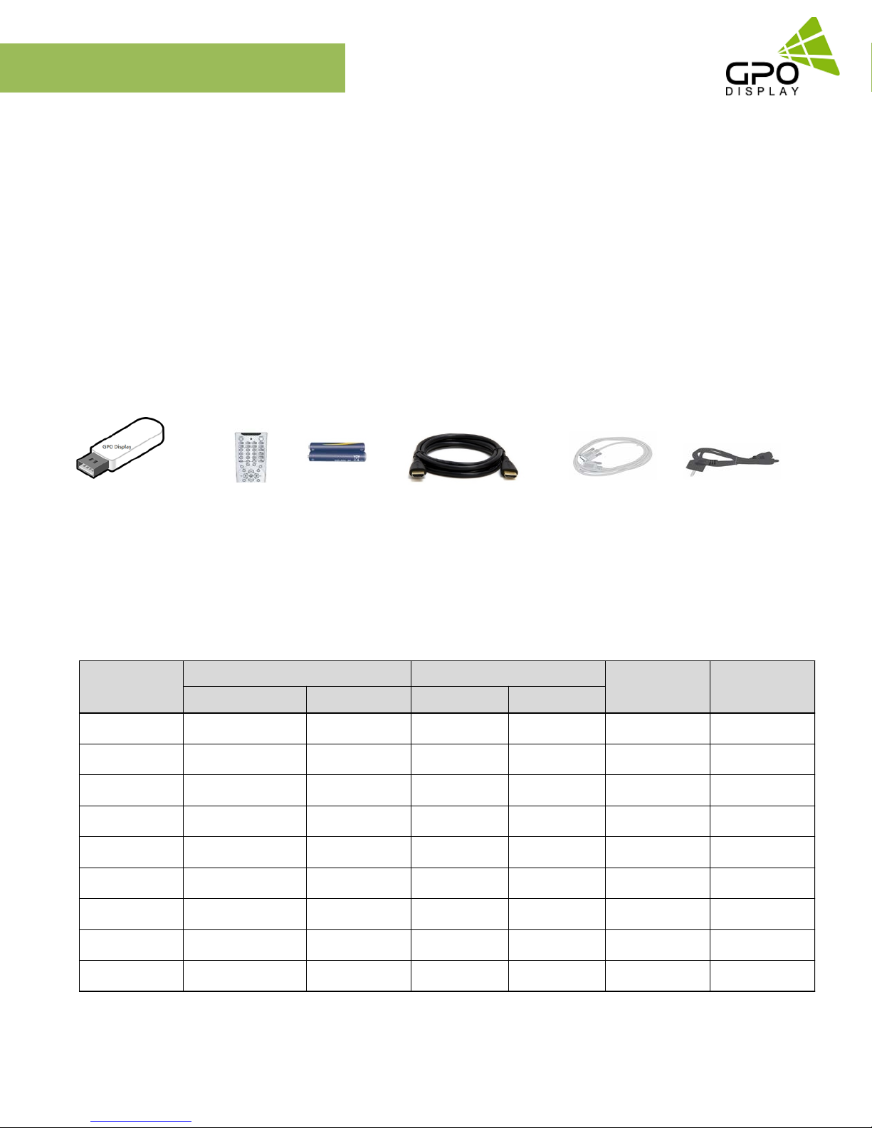
Accessories
EK-series
Video wall
User Manual &
Wall control program
Dimensions & BTU
Model
EK46MSU 40.23x22.7x4.03 55lbs 46x29x8 67lbs 150W 512
EK46HSU 40.23x22.7x4.03 55lbs 46x29x8 67lbs 190W 648
EK49MLU 42.43x23.9x4.09 63lbs 46x29x8 75lbs 90W 307
EK55MLU 47.77x26.94x4.06 78lbs 53.5x33x12 94lbs 175W 597
EK55HLU 47.77x26.94x4.06 78lbs 53.5x33x12 94lbs 255W 870
EK55MSU 47.8x27.03x4.06 75lbs 53.5x33x12 94lbs 170W 580
Remote
Controller
W x H x D (in) weight (lbs) W x H x D (in) weight (lbs)
Batteries
(AAA x 2)
Net Gross (Packed)
HDMI Speed Cable
RS232C Cable
Consumption
Power
Power Cable
BTU/h
EK55HSU 47.8x27.03x4.06 75lbs 53.5x33x12 94lbs 230W 784
EK55MLE 47.71x26.88x3.97 76lbs 53.5x33x12 92lbs 170W 580
EK55HLE 47.71x26.88x3.97 76lbs 53.5x33x12 92lbs 230W 784
www.gpodisplay.com EK-series Video w all
3
Handling Precautions
To ensure safety, please read this manual carefully before installation and follow the instructions
herein. Store this installation guide in a secure place for future reference.
• The video wall must be installed on a flat and level surface which is strong enough to bear its weight.
• Make sure mounting brackets are tightened and secured on the wall
• The Liquid Crystal Display (LCD) panel of the display has a very thin protective layer of coating
which is susceptible to marking or scratching, and cracking if struck or pressured. Please cover and
protect the displays if there is construction or other work being conducted at the installation site.
• Transport and handle displays by holding the handles on the back of the display. Do not touch the
LCD panel surface directly to avoid possible scratches and backlight leakage
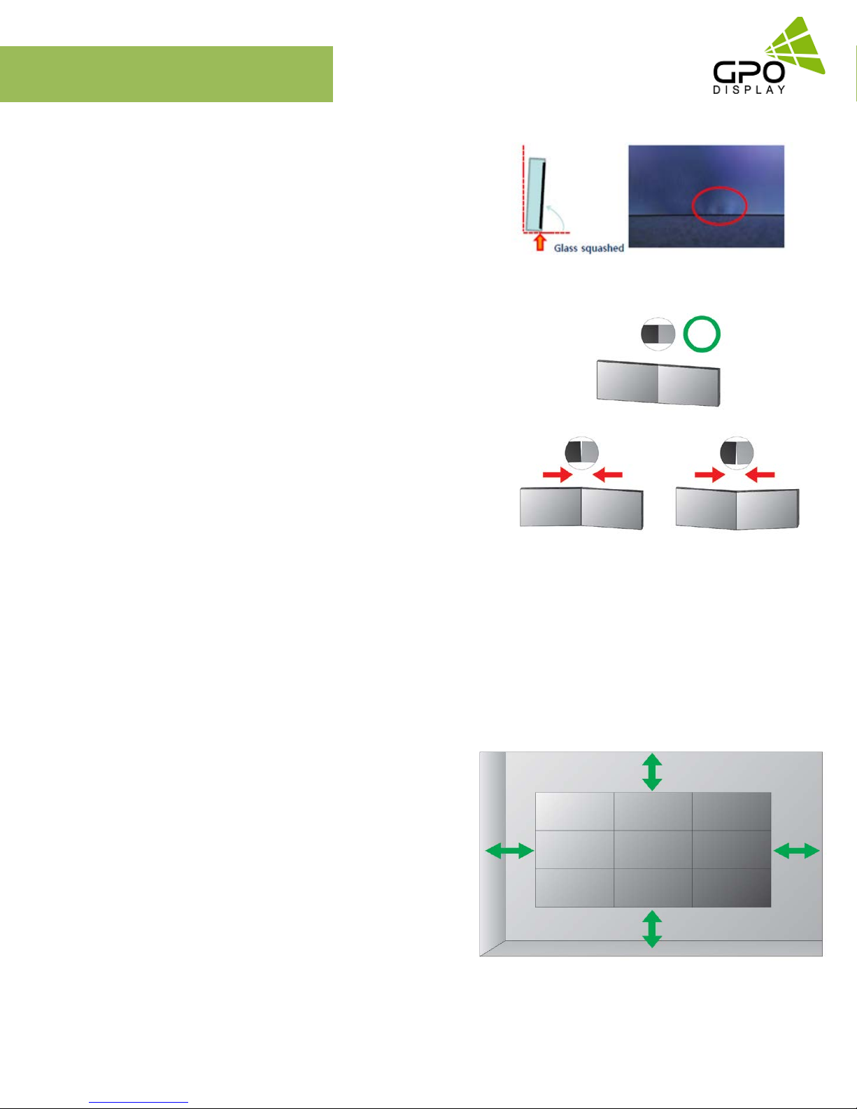
• Leave a slight (>0.5mm) gap between displays in order to protect your LCD screens from the damage
through the direct transfer of weight. See Checking the safe distance between displays on page 6 for
details.
[Fig. 1]
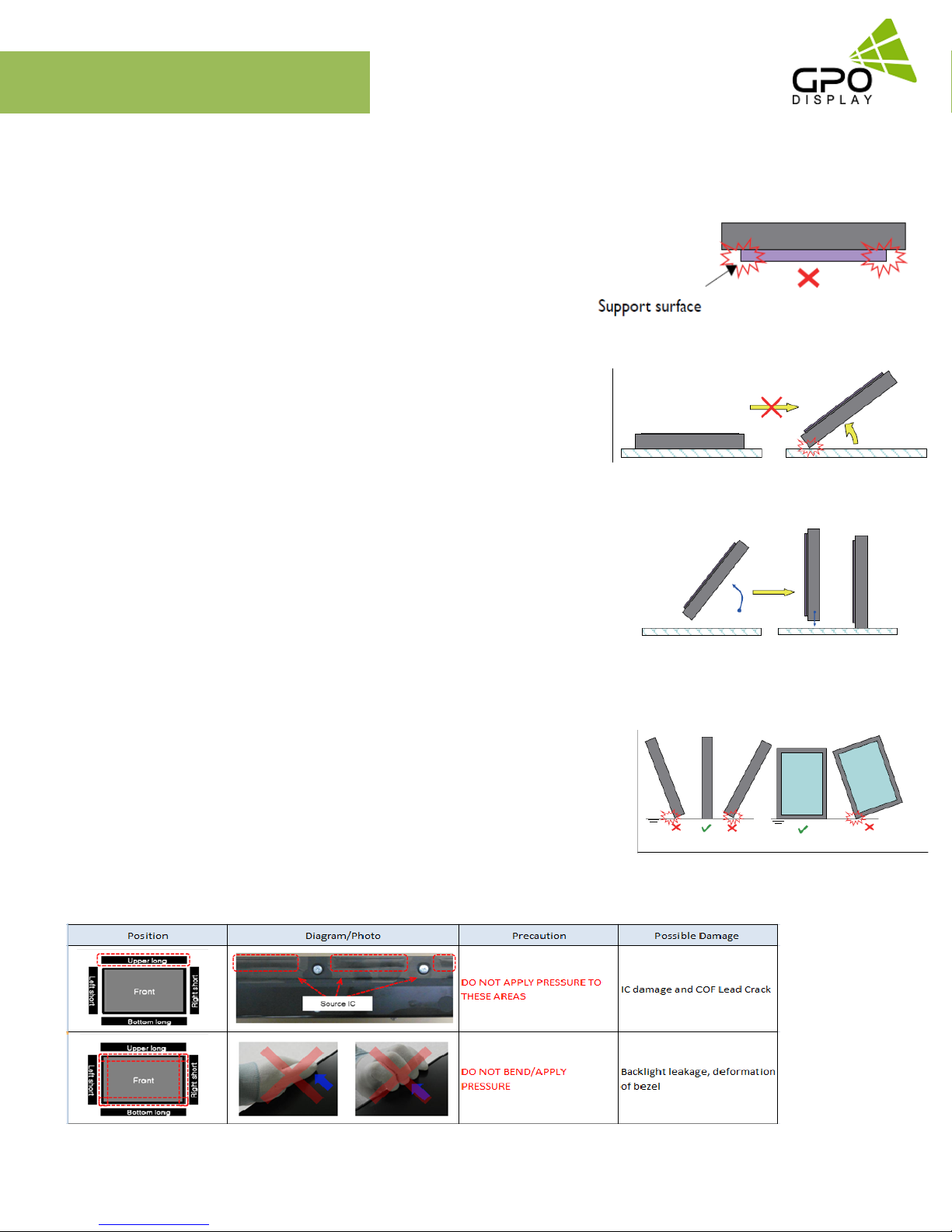
Notes on handling/transporting displays:
LCD video wall monitors have limited mechanical strength. To prevent the display from performance
failure caused by line defects, front bezel bending, glass scratch/broken, light leakage, etc.,
handle with care.
• At least two (2) adults are required to move & carry displays.
• Retain the original shipping box and packaging in storage for use in the future, when you may need
to transport the product.
• When placing the display face (panel side) down:
- Prepare a flat, level, horizontal surface that is larger than the display and spread a thick protective
sheet/foam on it. (Fig. 1) – Lay the display down gently and horizontally.
• When you want to place the display in an upright position:
- Lift the display up horizontally by holding the two (2) handles at the top/rear with one hand per
person and supporting the bottom bezel with the remaining hand. Do not allow the display to
rest/put weight on bezel edges and corners
- Be careful not to scratch any parts of the display when placing the display upright. (Fig. 3)
- Stand the display vertically to make sure the its weight spread evenly throughout the bottom bezel.
* Do not rest on corners or lean forward/back. (Fig.4)
[Fig. 2]
[Fig. 3]
[Fig. 4]
www.gpodisplay.com EK-series Video w all
4
Installation Precautions
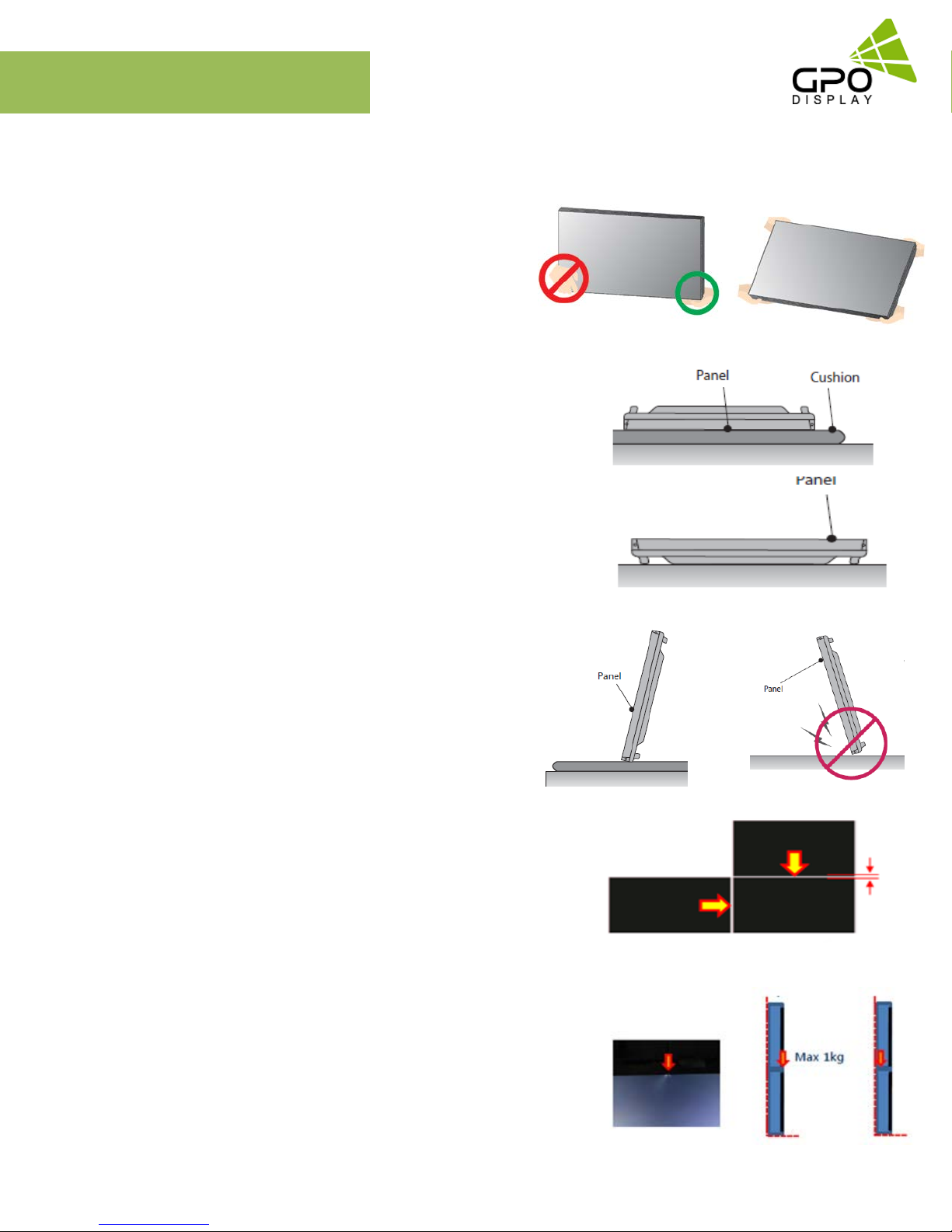
How to carry the product
At least two people are required to carry the display. When
carrying the product upright, please hold the handles on the rear
as well as the bottom of the display simultaneously for stability.
When carrying the product with the panel positioned upwards as
shown below, please hold as shown in the diagram.
When laying down the product, lay a cushion on a flat floor. Put the
product on it with the panel the product facing down.
EK-series
Video wall
If there is not a cushion available, ensure the floor is clean and then
lay the product down carefully with the panel facing either upward
or downward. At this time, be careful for objects not to fall on the
panel.
If the product needs to be set upright, hold both sides of the
product, and tilt backward carefully for. Do not let the panel to
touch the floor. If the product is tilted onto the bezel, the bottom of
the panel may be damaged.
A minor gap between monitors is strongly recommended
High temperatures can cause slight expansion of panels.
If there is no space between panels, damage may occur as a
result of pressure resulting from the expansion of adjacent
panels into one another.
* Recommended gap between displays: 0.5mm - 1.3mm
If more than 1kg of weight is applied to the top bezel of a panel
(as illustrated to the right), backlight leakage will result. This is a
sign that the panel alignment/angle must be adjusted or other
countermeasures must be applied.
www.gpodisplay.com EK-series Video w all
5
Installation Precautions
Bottom of product: When resting panel on any surface
(padded table, floor), do not tilt panel forwards as shown in
the diagram below. The weight of the display applied in an
uneven manner can result in damage.
During installation, do not apply pressure to any surface of
the panel. Damage to the panel may result from external pressure
or even minor impact to the panel. Physical and cosmetic damage
to displays is not covered under warranty.
EK-series
Video wall
Please ensure alignment on the Z-axis for a level plane across
adjacent panels (as shown in the diagram below). If precautions are
not heeded, GPO Display will not accept responsibility for any
Failure due to such installation errors.
Do not cover fan ventilation holes
Carefully install EK-series displays so as not to cover the fan air holes with any structural object.
If the holes are covered with anything, the inner temperature can be raised rapidly and it can cause malfunction.
Dimensions below are minimum required for proper ventilation
Ventilation space must not be covered or closed off at the front of the
opening. If for some reason the opening needs to be covered, other means
of ventilation will need to be incorporated into the design. Contact GPO
Display for design review and recommendations.
Please secure minimum clearance as shown in the picture for adequate
ventilation and technical service.
3.9” [100mm]
XX
3.9” [100mm]
3.9” [100mm]
Ventilation space in front of EK-Series displays must be furnished for heat
dispersion. If the area in front of EK-series displays must be sealed, there
must be consideration for the heat dispersion on the rear side of EK-series to
compensate.
www.gpodisplay.com EK-series Video w all
6
3.9” [100mm]
Set up for Operation
Remove Protective Pads Before Installation
Make sure that the protection pads are removed
from each corner before installing the product.
(Note: Only for Extreme Narrow Bezel, <2mm combed bezel displays)
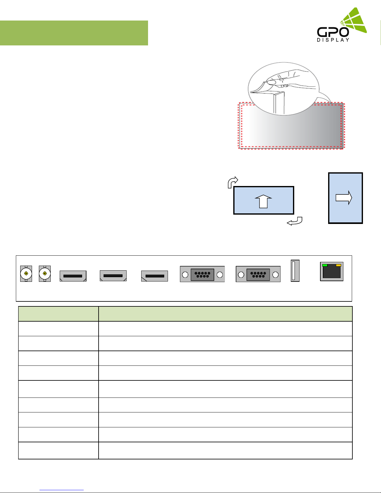
To Install in Portrait Orientation
When installing in Portrait Orientation, rotate the monitor clockwise
90 degrees (when facing the screen).
EK-series
Video wall
Input / Output Terminal
HD-SDI
IN /OUT
Interface Description
HDMIOUT • High Definition Output – output for the HDMI input only
HDMI IN • High Definition Multimedia Input – up to 3840x2160 @60Hz (HDMI 2.0)
DP IN • DisplayPort Input – up to 3840x2160 @60Hz (v1.2a)
RS-232 IN • Serial control input
RS-232 OUT
USB • Download - software update
HD-SDI IN (OPTIONAL) • Serial digital Interface Input (Optional: Models ending in –”B” only)
HDMI
OUT
HDMI
IN
• Output for serial control (daisy-chaining of control signal)
DP
IN
RS-232C
IN
RS-232C
OUT
USB ETHERNET
D/L RS-232C
HD-SDI Out (OPTIONAL) • Serial digital Interface Output (Optional: Models ending in –”B” only))
ETHERNET (RS-232)
www.gpodisplay.com EK-series Video w all
• Communication Port via Ethernet
7
Set Up for Operation
Key Pad
The image may be different according to the model.
Button Name Operation
EK-series
Video wall
PowerKey
MenuKey
SelectKey
Up Key
DownKey
LeftKey
RightKey
► PowerOn/Off.
► Activates main OSD menu interface.
► Navigates to higher menu in main OSD menu.
► Stops auto frequencysearching function.
► Exits OSDmenu.
► Activates OSD menu of input source selecting.
► Changes input source by selecting.
► Executes functions (by OSD help commands) in main OSD menu.
► Increases program number & tune channel.
► Navigates inputsource.
► Executes function (by OSD help commands) in main OSD menu.
► Navigates previous menu in main OSD menu.
► Decreases program number & tune channel.
► Navigates inputsource.
► Executes function (by OSD help commands) in main OSD menu.
► Navigates next menu in main OSD menu.
► Decreases sound volume of speaker.
► Executes function (by OSD help commands) in main OSD menu.
► Decreases values of user menu in main OSD menu.
► Increases sound volume of speaker.
► Executes f unction (by OSD help commands) in main OSD menu.
► Increases values of user menu in main OSD menu.
IR LEDStatus
Status Color Indicator Status
Power Off Red On
Normal Green On
No signal Green Blink
DPMS Red Blink
Download Green Fast Blink
www.gpodisplay.com EK-series Video w all
8

Set Up for Operation
GPO Display’s video wall displays have a built-in video wall processor that allows for virtually any matrix size of LCD video wall. In this
manual, instructions for a 2x2 configuration will be used as an example.
1. Installation
To install EK Series displays in video wall configuration, please read the installation directions carefully before installation is performed.
These monitors can be installed for single display/”standalone” operation, in a single row, or in multiple rows. The highest Display Sequence
number is 99. Contact GPO Display for arrays comprised of more than 99 displays.
CAUTION: Never connect or disconnect cables from the display when the display is powered on as this may cause serious
damage.
2. Installation Requirement
2.1 Structure for the installation
Support structure design and construction for the display installation is the customer’s or its installer’s responsibility. GPO Display does
not take any responsibility on design or construction of installations. The minimum requirements for space, strength of the structure,
electronic, heat dissipation and environmental condition is described in the following. If any further information or support is needed
from GPO Display, please contact us in advance to ensure ample time for support. We will be glad to help with any recommendations or
information. Call 510-659-9855 or e-mail
support@gpodisplay.com.
2.2 Power Requirements
Please refer to the specifications for power consumption of displays to be installed (Page 4)
Do not plug more than two units into a given receptacle (example: all displays in 2x2 should not be plugged into quad receptacle
Using more than 70% of current on the AC circuit is strongly discouraged. Clean AC power is required for “noiseless” screen images.
Avoid damages inflicted by power glitches or surges- either a power conditioner or surge protector is recommended. Contact your
electric power specialist for consultation.
3. Heat Dissipation
Recommended LCD operational conditions are:
Temperature: 32°F -104°F Humidity: 20-80%
4. General Information
1.1 PC Settings:
PC’s need to be set to an appropriate graphics mode that has the same resolution with the panel to have clear screen image. And
the vertical refresh rate should be set to 56~75Hz, non–interlaced signal. The controller has been designed to take a very wide
range of input signals however to optimize the PC’s graphic performance we recommend choosing 60Hz vertical refresh rate: this will
prevent screen flicker. If you wish to view 4k2k@60Hz resolution, must use the PC that supported HDMI 2.0 (or DisplayPort 1.2).
1.2 Signal Quality:
Signal quality is very important: If there is noise or instability in the PC graphics output, this may result in visible noise on the
display. Refer to the graphic modes table in specification section for supported modes. Non-interlaced & interlaced video input is
acceptable. Please use the HDMI 2.0 dedicated cable. (4K2K@60Hz)
www.gpodisplay.com EK-series Video w all
9
Set Up for Operation
Note:
If you turn the monitor on when the set is cold, the screen may flicker. This is normal.
Sometimes red, green, or blue spots may appear on the screen. This is normal.
Use a High Speed HDMI®/TM cable.
Use a certified cable with the HDMI logo attached. If you do not use a certified HDMI cable, the screen may
not display or a connection error may occur.
Recommended HDMI® Cable Types
- High-Speed HDMI®/TM Cable
- High-Speed HDMI®/TM Cable with Ethernet
Connect the signal input cable and tighten it by turning the screws clockwise (if applicable).
Avoid displaying static images on the screen for a long period of time to prevent image burn. Use a
screensaver if possible.
Prior to insertion of the next set into neighboring mount, insert cables from the outputs of the first set into the
inputs of the second set.
If you cannot hear any sound in HDMI mode please check your PC settings. Some PCs require you to
manually change the default audio output to HDMI.
Apple computers may require an adapter to connect to this monitor. Call or visit their web site for more
information, or consult with GPO Display.
Connect the signal input cable and tighten it by turning the screws clockwise.
Do not press the screen with your finger for a prolonged period as this may result in temporary distortion on
the screen
A wireless communication device near your monitor can affect the image.
www.gpodisplay.com EK-series Video w all
10
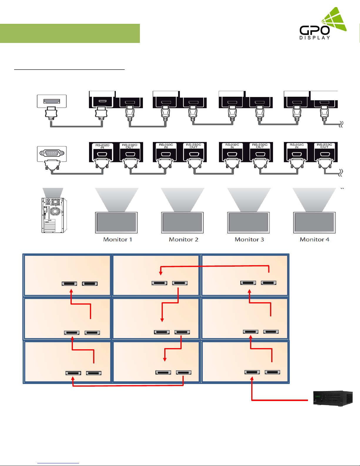
Cabling Set up
Daisy-Chaining Monitors
HDMI
RS232
HDMI IN
HDMI Out
HDMI IN
HDMI Out
HDMI IN
HDMI Out
HDMI IN HDMI Out
Set ID
#1
Set ID
#4
Set ID
#7
HDMI IN
HDMI IN
HDMI IN
HDMI Out
HDMI Out
HDMI Out
Set ID
#2
Set ID
#5
Set ID
#8
HDMI IN
HDMI IN
HDMI IN
HDMI Out
HDMI Out
HDMI Out
Set ID
#3
Set ID
#6
Set ID
#9
HDMI IN
HDMI IN
HDMI IN
HDMI Out
HDMI Out
HDMI Out
Note:
If the signal cable between the product and your PC is too long, make sure to use the signal booster or optical cable.
www.gpodisplay.com EK-series Video w all
11
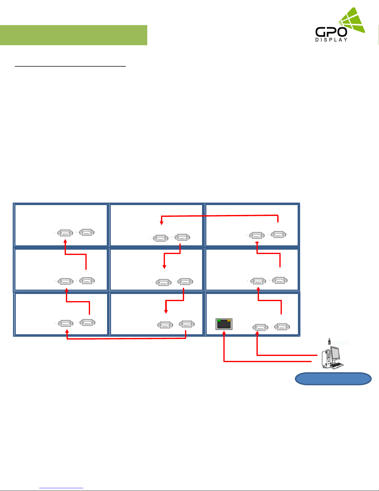
Cabling Set up
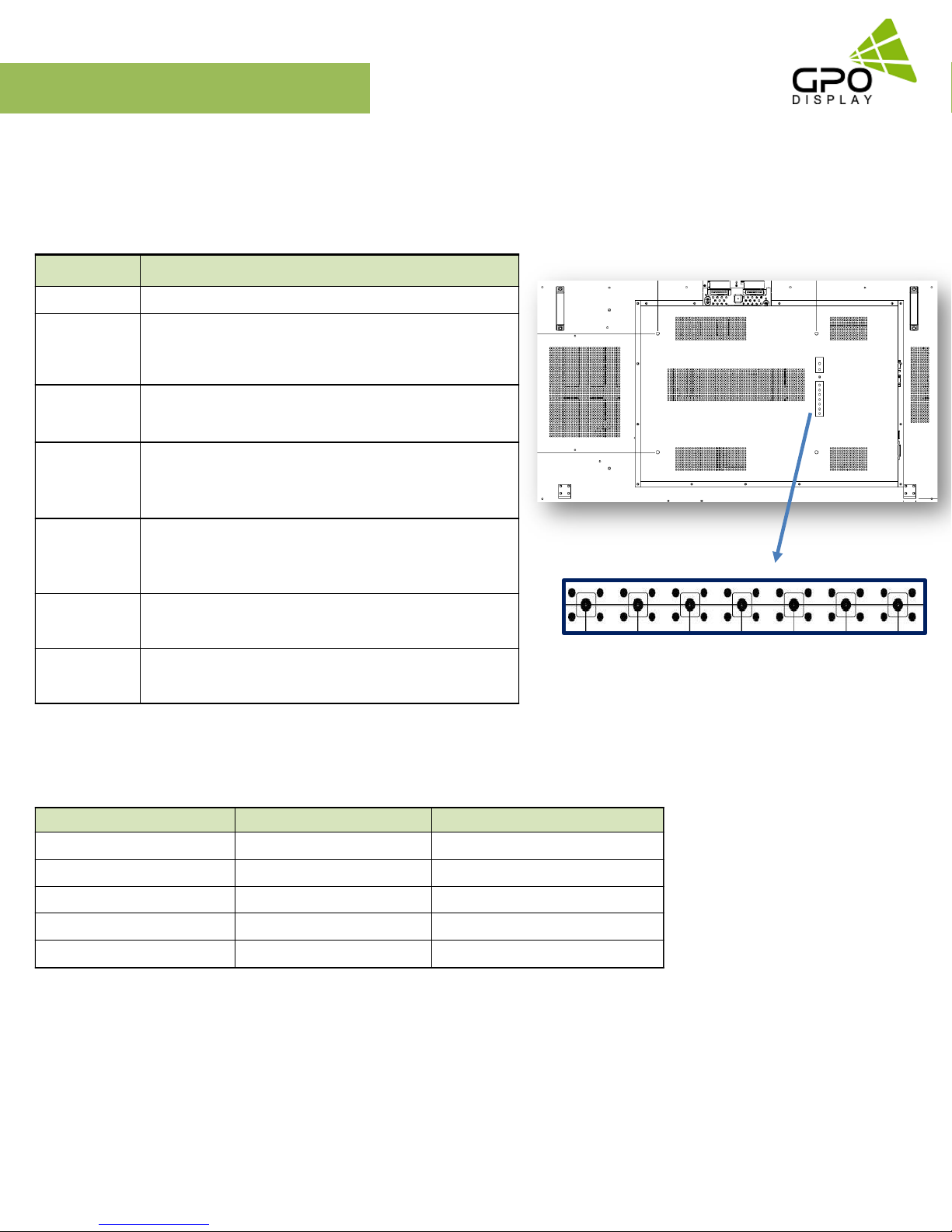
Connect RS-232 Cables
1. While mounting display, insert any cables used for Power, video inputs or outputs into the set.
2. Prior to insertion of the next set into neighboring Wall Unit, insert cables (including RS-232) from the outputs of the first set into
the inputs of the second set.
3. Repeat steps 1-2 for next set, if necessary.
4. The RS-232 daisy chain limitation is listed as 30 displays, although theoretically more units can be accommodated.
5. Daisy-chaining can be initiated from any unit but it is strongly recommended that you start with a display on the bottom row for
ease of access. There is no terminator at the end of the unit. It is always recommended to record/make note of the chaining diagram
as it is crucial to determining issues with communication.
Set ID #1
Set ID #4
Set ID #7
RS232 IN
RS232 IN
RS232 IN
RS232 Out
RS232 Out
RS232 Out
Set ID #2
Set ID #5
Set ID #8
RS232 IN
RS232 IN
RS232 IN
RS232 Out
RS232 Out
RS232 Out
Set ID #3
Set ID #6
Set ID #9
RS232 IN
RS232 IN
RS232 IN
RS232 Out
RS232 Out
RS232 Out
RJ45 Input OR RS232 input
www.gpodisplay.com EK-series Video w all
12
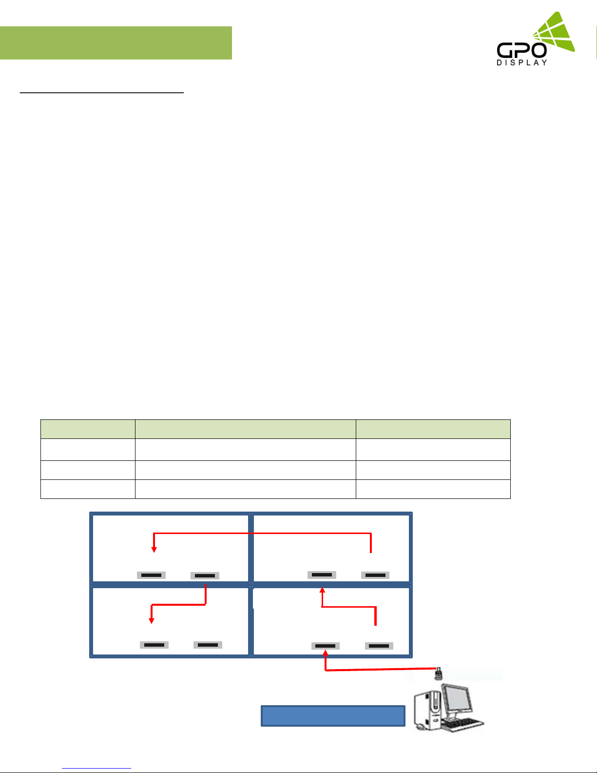
Cabling Setup
Connect Video Cables
1. After mounting display, insert any cables used for Power, inputs or outputs into the set.
2. Prior to insertion of the next set into neighboring mount, insert cables from the outputs of the first set into the inputs of the second set.
3. Insert any cables which are to be connected to the third set into the outputs of the second set. Connect these cables into the inputs of
the third set.
4. Repeat steps 1-3 for fourth set, if necessary.
Supports HDMI 4K x 2K input – HDMI, DP
Supports the daisy chain mode of 4K2K resolution. (HDMI input only)
Recommended HDMI Cable Types
- High-Speed HDMI®/TM Cable
- High-Speed HDMI®/TM Cable with Ethernet
Some installation sites have a high level of Electric Noise which may appear onscreen, especially with HDMI.
Digital noise may appear due to poor quality HDMI cabling. If the video signal needs be delivered from a distance, electric noise
must be accounted for. If the signal cable between the product and your PC is too long, make sure to use the Booster or optical cable.
HDMI and DisplayPort are HDCP-compliant.
HDCP 2.2 Compliant HDMI 2.0 Compliant Display Port v1.2a Compliant
Signal-looping specifications (Only HDMI input / DP port doesn’t support daisy-chain function)
Input Resolution SPEC Remarks
3840x2160@60Hz Supports up to 9 units Use only HDMI 2.0 cables
3840x2160@30Hz Supports up to 16 units
Daisy-chaining not recomm ende d
1920x1080@60Hz Supports up to 25 units
Set ID #1
HDMI IN HDMI OUT
Set ID #3
Set ID #2
Set ID #4
HDMI IN
HDMI OUT
HDMI IN
HDMI OUT
HDMI IN
HDMI OUT
Up to 3840 x 2160 @60Hz
www.gpodisplay.com EK-series Video w all
13
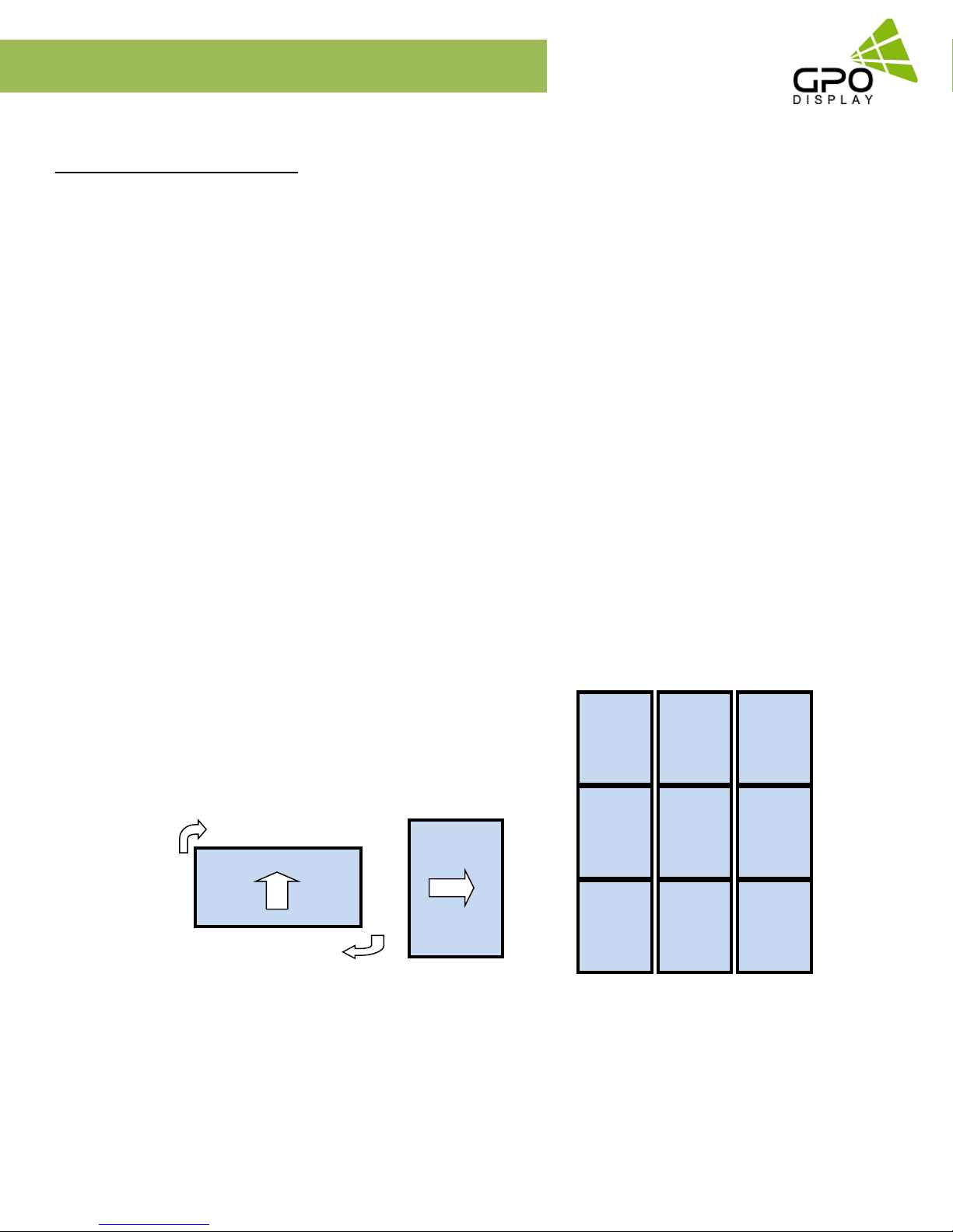
Configuration of Video Wall Displays
Matrix Configuration
Landscape
1. This is most common configuration, as it retains the native HD aspect ratio of 16:9,
The number of units in rows and columns should be the same to maintain aspect ratio.
2. If the number of units in rows and columns are different (ex: 2x5), the content must be arranged to match the screen
format accordingly. Images will be stretched according to the number of Horizontal & Vertical Set counts if content from
a particular input is shown on the entire wall.
Portrait
1. Rotate units 90° clockwise to install in portrait mode.
2. The X position and Y position number should be set as if it is configured in landscape mode.
3. The X max is number of rows and the Y max is number of columns in this configuration,
4. The input image should be rotated clockwise 90°.
*GPO Display provides both landscape and portrait wall mount systems separately. Before ordering, please verify which orientation
is compatible with your system.
Set 1
X position: 1
Set 4
X position: 1
Set 7
X position: 1
Y position: 3
Set 8
X position: 2
Y position: 3
Set 9
X position: 3
Y position: 3
Y position: 2
Set 5
X position: 2
Y position: 2
Set 6
X position: 3
Y position: 2
Y position: 1
Set 2
X position: 2
Y position: 1
Set 3
X position: 3
Y position: 1
Note: If an external video processor is employed, please refer to your video processor’s manual.
www.gpodisplay.com EK-series Video w all
14
Configuration of Video Wall Displays
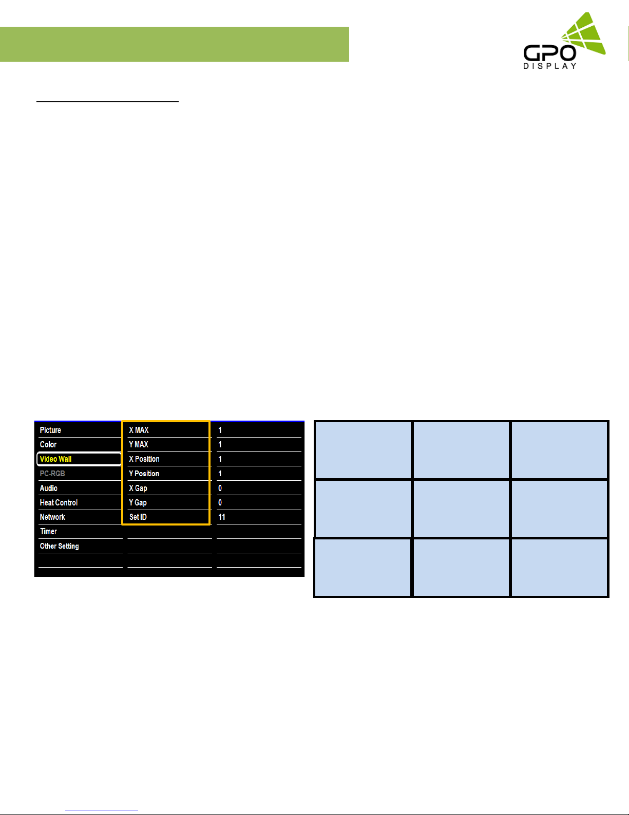
Video Wall Setting
MENU → Video Wall
X max
This function divides the video signal according to the specified number of horizontal displays. Enter the number of
horizontally-arranged displays in your array. The signal will be divided across the video wall horizontally according to this value.
A maximum of 10 displays can be assigned in horizontal arrangement.
Y max
This function divides the video signal according to the specified number of vertical displays. Enter the number of
vertically-arranged displays in your array. The signal will be divided across the video wall vertically according to this value.
A maximum of 10 displays can be assigned in vertical arrangement.
X position / Y position
Users may change displays’ positions in the array by adjusting X and Y Position values. The X position value indicates the display’s
position (numbered moving left-to-right) in the array according to the X max value (see diagram below). The same concept applies
to the Y position value (numbered moving top-to-bottom) according to the Y max value.
Example. 3 X 3 Video Wall layout setting
X Max
Y Max
: Maximum number of columns for which video wall layout is supported (10)
: Maximum number of rows for which video wall layout is supported (10)
X position : Coordinate of display/video signal column position.
Y position : Coordinate of display/video signal column position.
Set ID: 1
X max: 3
Y max: 3
X position: 1
Y position: 1
Set ID: 4
X max: 3
Y max: 3
X position: 1
Y position: 2
Set ID: 7
X max: 3
Y max: 3
X position: 1
Y position: 3
Set ID: 2
X max: 3
Y max: 3
X position: 2
Y position: 1
Set ID: 5
X max: 3
Y max: 3
X position: 2
Y position: 2
Set ID: 8
X max: 3
Y max: 3
X position: 2
Y position: 3
Set ID: 3
X max: 3
Y max: 3
X position: 3
Y position: 1
Set ID: 6
X max: 3
Y max: 3
X position: 3
Y position: 2
Set ID: 9
X max: 3
Y max: 3
X position: 3
Y position: 3
www.gpodisplay.com EK-series Video w all
15
Configuration of Video Wall Displays
Video Wall Settings
Full Mode / Natural Mode
MENU → Video Wall
Full Mode: X gap: 0 ; Y gap: 0
Natural Mode
UNB (B2B 3.5mm): X gap: 3 ; Y gap: 5
ENB (B2B 1.8mm or 1.7mm): X gap: 2 ; Y gap: 3 or : X gap: 2 ; Y gap: 2
Sets Bezel Compensation for a “Natural” Tiled Image (some content
will be hidden behind bezels)- this approach appears less “interrupted”
than “Full Mode”.
X gap: Value= (int)(1000xGap/Active)
Example) 55” Ultra Narrow Bezel Video Wall
- Horizontal Active Panel Area: 1,209.6 mm
- Horizontal GAP: 3.5 mm
Value = (int) ((1,000 x 3.5)/1,209.6) = (int)2.89 = 3
Y gap: Value = (int)(1,000 x Gap)/Active)
Example) 55” UNB Video Wall
- Vertical Active Panel Area: 680.4mm
- Vertical GAP: 3.5 mm
Value = (int) ((1,000 x 3.5)/680.4) = (int)5.1 = 5
Active
X GAP
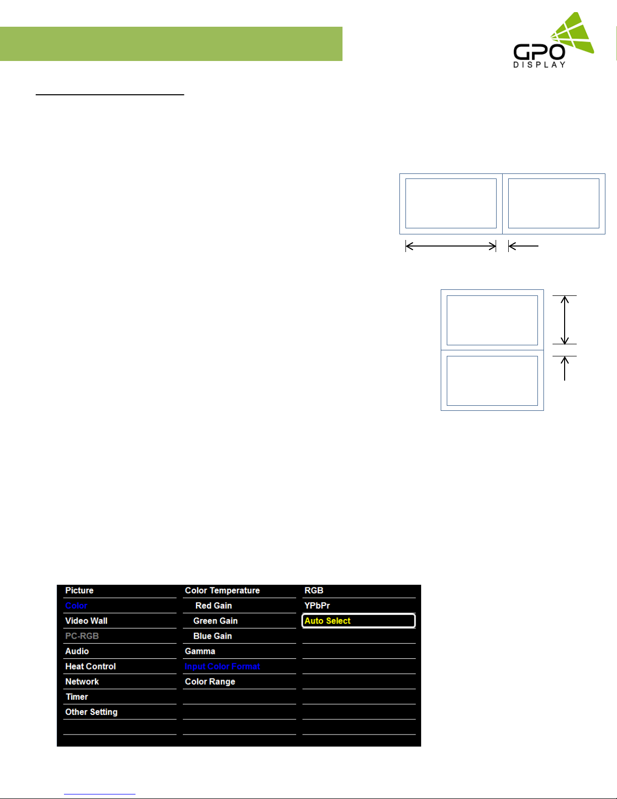
Auto switch Video Input color Format
MENU → Input Color Format → Auto Select
If the display is powered on with Input color format Auto On, and the previously-used video source selection is not active,
Active
Y GAP
the display will automatically search each video input source for active video.
Check the color space of the input signal before adjusting values [ RGB / YPbPr422(YPbPr444)]
www.gpodisplay.com EK-series Video w all
16
EK-series
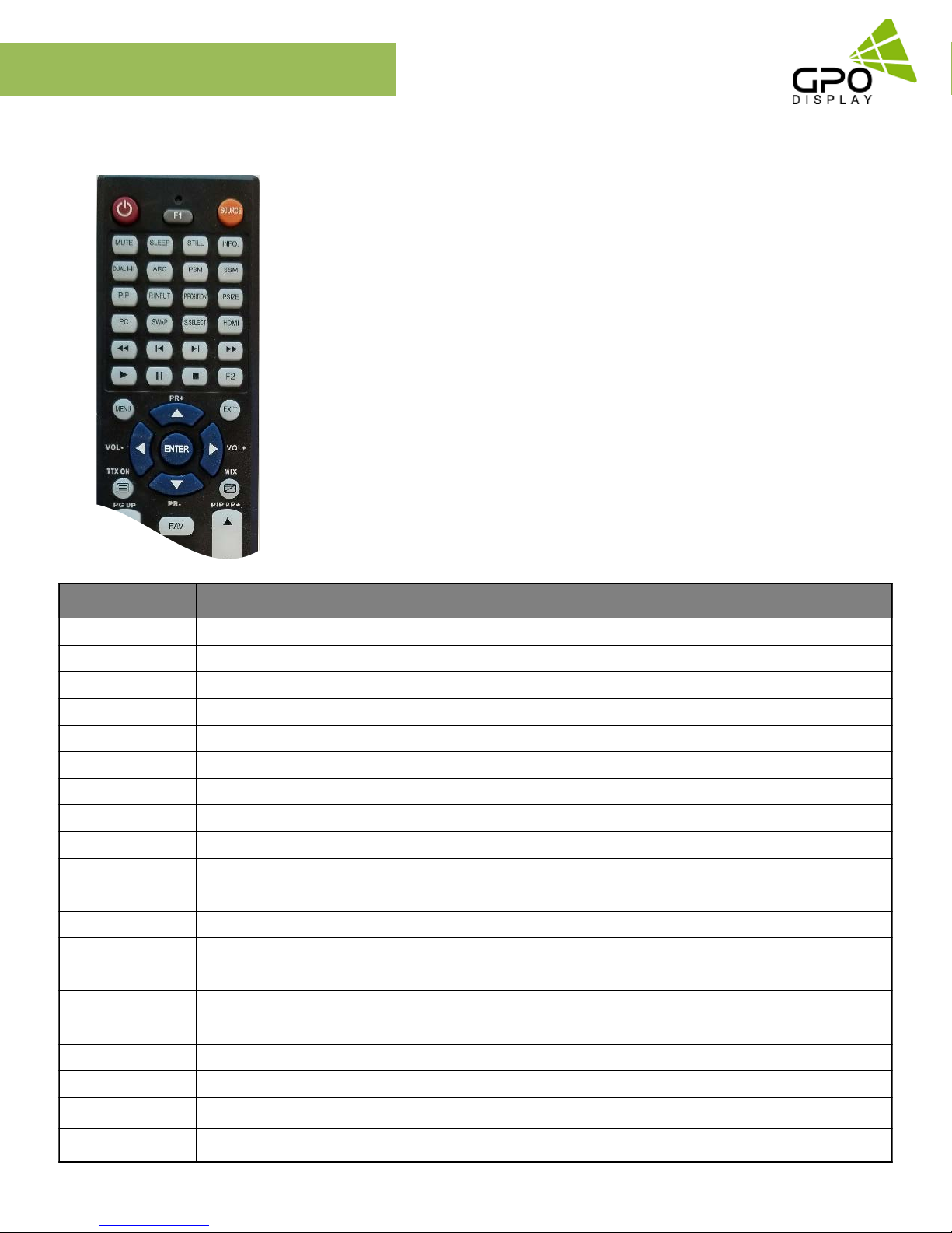
Remote Control
Video wall
1. SOURCE: Selects Input Source
2. POWER: Turns the LCD Display On and Off
3. UP: Controls the UP cursor in the menu
4. LEFT: Controls the LEFT cursor in the menu
5. RIGHT: Controls the RIGHT cursor in the menu
6. ENTER: Controls the ENTER cursor in the menu
7. DOWN: Controls the DOWN cursor in the menu
8. MENU: Displays the main On-Screen menu
9. EXIT: Exit the On-Screen menu
KeyName Description
Power
Menu
Up
Down
Right
Left
Enter
EXIT
Info
Sleep
Mute
Source
ARC
► Power On/Off
► Same as “Menu key” on keypad.
► Same as “Up key” on keypad
► Same as “Down key” on keypad
► Same as “Right key” on keypad
► Same as “Left key” on keypad
► Same as “Select key” on keypad
► Exit OSD menu
► Displays input source information
► Set minimum sleep timer value more than current sleep timer value when sleep timer OSD activated
► If sleet timer is maximum value, disables sleep timer
► Toggles sound status of speaker/headphone in mute.
► Activates OSD of source change.
► Deactivates OSD of source change.
► Activates OSD of aspect ratio control.
► Deactivates OSD of aspect ratio control.
STILL
0~9
BLUE
RED
www.gpodisplay.com EK-series Video w all
► Toggles picture status between motion and still image.
► Enter digit value to Active SET ID
► Set Active SET ID
► Delete Active SET ID
17
EK-series
OSD Menu
Most menus consist of three levels to set up the options, but some require greater depth for the variety of settings. If you press the
MENU button, up to the third level of the menu system will appear on the monitor screen. The fourth level can be displayed by
pressing the OK button
To show and remove the Menu:
Press the MENU button on the Remote Control to display the menu. A second press of the MENU button or a press of the
EXIT button will take you back to monitor viewing.
To go to the next level:
Press OK (or Right arrow button) on the Remote Control.
To go back to the previous level:
Press MENU (or Left arrow button) on the Remote Control.
To go to the next menu:
Press Down arrow button on the Remote Control.
To go to the previous menu:
Press Up arrow button on the Remote Control
Video wall
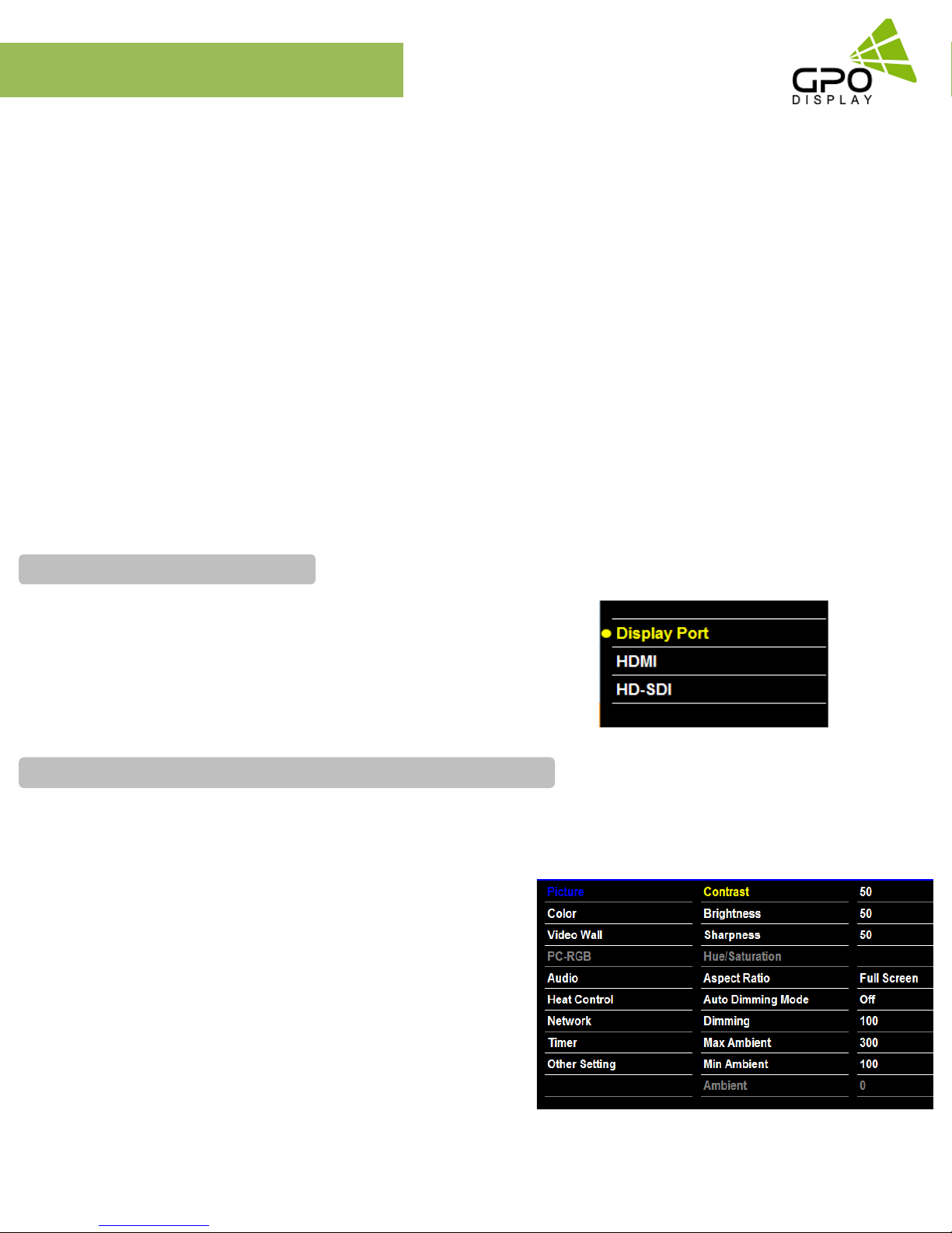
To set Input Source
Source: Display Port, HDMI (HD-SDI: Optional)
Source → Input Source
To use, press the SOURCE key and then arrow keys to select desired video
source. Press the OK button to go to desired video source
To fine-tune the picture mode Contrast / Brightness /Sharpness
Adjust the picture appearance to suit your preference and viewing situations.
Picture → Contrast Brightness or Sharpness → Adjustment
Press the MENU button to select the PICTURE mode
Press the OK button or arrow key to select Contrast menu.
Press the OK key or arrow key to select Adjustment menu.
Press the arrow key to make desired adjustments.
Press MENU key or arrow key to return to the previous menu.
Or, in order to exit the menu at any time, press the EXIT key.
• Brightness: adjusts the overall brightness of the screen
• Contrast: adjus ts t he di ffere nce be t we en the light and d ar k
areas of the picture.
• Sharpness: adjust s the sharpness of the edges of objects
www.gpodisplay.com EK-series Video w all
18
EK-series
OSD Menu
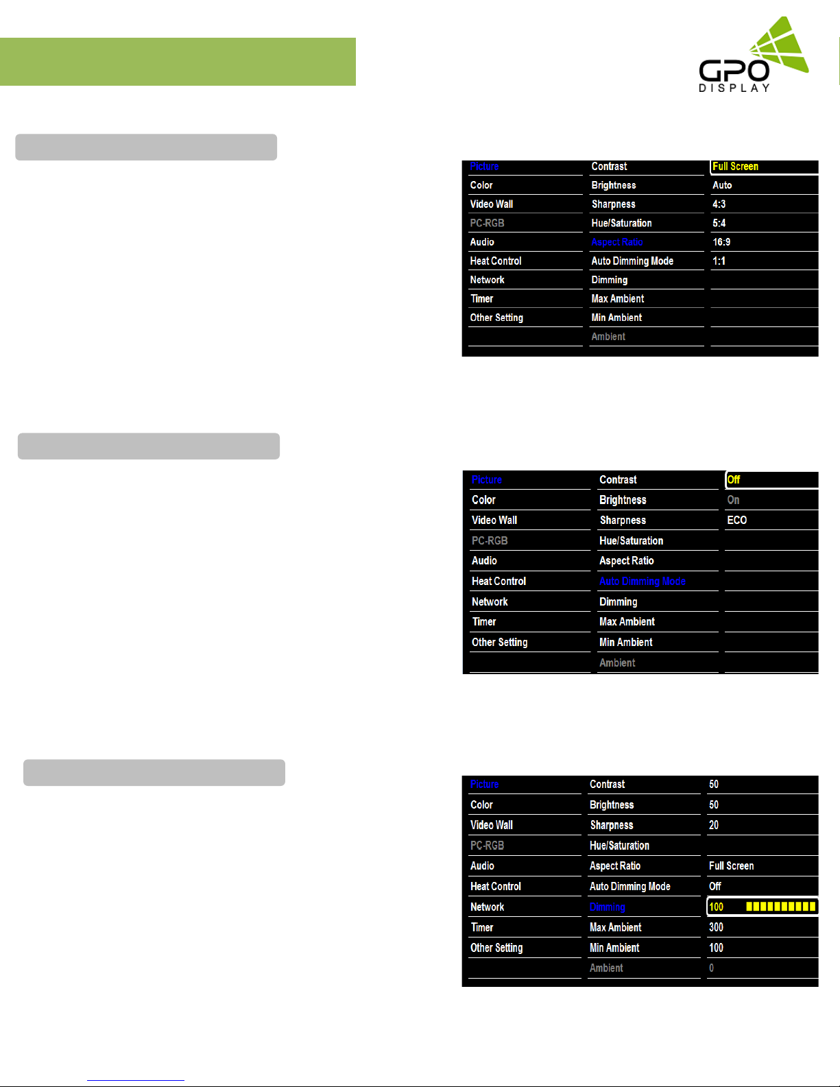
To Set Aspect Ratio
Changes the aspect ratio to view the image in its optimal size.
Picture → Aspect Ratio→ Adjustment
Press the MENU button an d selec t the PICTURE mode.
Press the OK button or arrow key and then select Aspect Ratio
menu.
[ Full Screen, Auto, 4:3, 5:4, 16:9, 1:1 ]
To Use Auto Dimming Function
Video wall
Automatic dimming controls by light sensor in Dimming menu
(Only applies to certain models)
Picture → Auto Dimming Mode→ Adjustment
• Off: Adjust the dimming level by the manual operation.
• On: Adjust the dimming level by the data of light sensor
(Ambient Light Sensor Option on ly).
• ECO: Reduces dimming level to 50.
To set Dimming
Manually adjust the brightness of the screen.
(Auto Dimming Mode – Off / Only applies to certain models)
Picture → Dimming → Adjustment
www.gpodisplay.com EK-series Video w all
19
 Loading...