

Satellite Tracking and Monitoring Solutions
®
Power Generation
Installation Guide
Contact gplink at +1.252.504.5113 at least 24 hours
prior to scheduled installation for activation of units.
(48 hours on weekends)
www.gplink.com

Contents
1. Introduction and Purpose 3
2. Installation & Components 4
2.1 Installation 4
2.2 Power Harness 4
2.3 J1939 Harness 5
2.4 MODBUS Harness 5
2.5 Analog Inputs and Outputs 6
3. 2-Inch User Interface 7
3.1 Operation 7
3.2 Diagnostics
4. gplink Concierge & Technical Support 11
4.1 Transferable Limited Warranty 11
2Power Generation Installation Guide Version 2.0.0 - July 2016
Contact gplink at +1.252.504.5113 at least 24 hours (48 on weekends)
prior to scheduled installation for activation of units.
1. Introduction and Purpose
Notice - The gplink system is only an aid to operation of the equipment it is installed on. The performance
of the system and the system performance specications can be affected by many factors including but
not limited to equipment failure, environmental conditions, improper installation, handling and/or use.
This device should not be used for any navigational or safety purpose. The gplink system is used at your
sole risk and in no event shall gplink, Inc. be held liable for any costs, losses, liabilities, damages, expense
or claims of any nature incurred or sustained in respect of this device or its use. You further indemnify and
hold harmless gplink Inc. and their partners from any liability or loss resulting from use of the device.
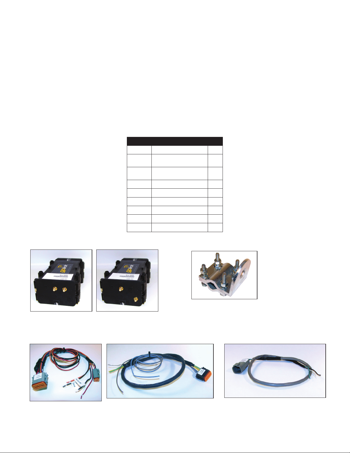
Parts List (Single Band)
Part # DESCRIPTION QTY.
AN9003
AN9004
GWD050
GWD051
HN9040 Power Harness 1
HN9044 J1939 CAN Harness 1
HN0671 Antenna Extension 2
HW0245 Mounting Hardware 1
BK9990 Antenna Mounting bracket 1
WI0020 Installation Manual 1
GPS/GSM antenna
GPS/Iridium antenna
GPLink (MTU) GSM
GPLink (MTU) Iridium
1
1
GWD050 - GSM GWD051 - Iridium BK9990
HN9041HN9040
HN9042
3Power Generation Installation Guide Version 2.0.0 - July 2016
2. Installation & Components
2.1 Installation
Locate an area to mount the antenna less than 3 meters from the Mobile Transmitting Unit (MTU). Mount the
antenna, using the Antenna mounting bracket (BK9990), and run the cables to MTU.
a) Mount the MTU in an area where there is easy access to antenna cables and the battery or power source.
b) GPS Connect the Blue colored wire to the J1 connector on the MTU.
c) GSM Connect the Yellow colored wire to the J2 connector on the MTU if connecting a GMS device.
or
SAT Connect the White colored wire to the J3 connector on the MTU if connecting an Iridium device
Connect cables to mounting location of the MTU.
J1 J2
J3
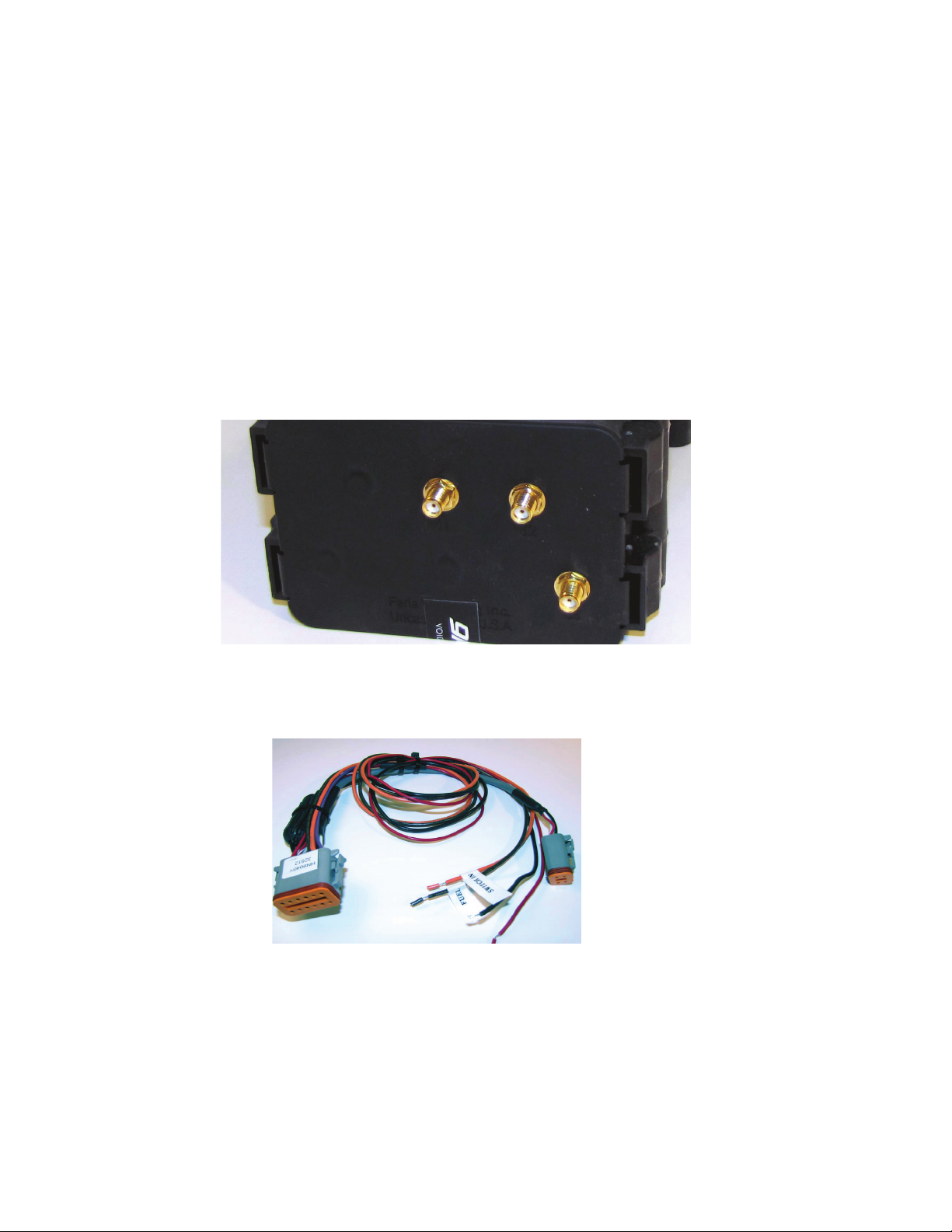
2.2 Power Harness
(HN9040) (See the Wiring Diagram)
4-pin
Deutsche
connector
A
a) Connect the power harness (HN9040) (Gray Connector (A)) to the MTU at receptacle “A”
b) Connect the RED wire directly to a continuous 12-24 vDC source or the positive battery terminal.
c) Connect the BLACK wire to a good ground, preferably the negative battery terminal.
Note: The connector and receptacle are keyed so that they can only go together one way. Please be sure to line up the
guides on the connector with the slots in the receptacle when connecting the harness to the MTU.
4Power Generation Installation Guide Version 2.0.0 - July 2016

2.3 J1939 Harness
(HN9041) (See the Wiring Diagram)
J1939 B
B
A
a) Connect the J1939 harness (HN9041) (Black Connector (B)) to the MTU at receptacle “B”.
b) Connect the GREEN (CAN High), YELLOW (CAN Low) and BARE (Shield) wires to the corresponding J1939
connector wires on the generator.
c) The BLUE and GRAY wires are available for use as outputs.
2.4 MODBUS Harness
(HN9042) (See the Wiring Diagram)
4-Pin
Deutsche
connector
a) Connect the four pin Deutsche connector to the Deutsche connector on the Power harness (HN9040).
b) Connect the WHITE (D+), GREEN (D-) and BLACK (Ground) wires to the corresponding connector on the
Genset controller.
Genset
Controller
5Power Generation Installation Guide Version 2.0.0 - July 2016

2.5 Analog Inputs and Outputs
BLACK
Ground
BROWN
Fuel
ORANGE
Switched IN
Shield
Output
Output
CAN (low)
CAN (high)
RED
BLUE
BARE
YELLOW
GREEN
Main
Battery
J1/GPS - Blue wire to Antenna
B
B
A
A
HN9040
HN9042
HN9041
Serial # KWD304-VMS000
FPN:KTW304
PASS 02-28-09
SIM CARD
IRIDIUM MODEM #
FCC ID:PY76220511
Not used - 1
Not used - 4
Not used - 5
Not used - 6
Output - BLUE - 2
Output - GRAY - 3
12 - Not used
11 - Not used
10 - Not used
8 - Not used
9 - BLACK
10 - RED
11 - WHITE
12 - GREEN
7 - BLACK - Ground
PURPLE - 1
Switched IN - ORANGE - 2
Fuel - BROWN - 3
Not used - 4
RED/WHITE - 5
RED - 6
9 - YELLOW - CAN(High)
8 - BARE - Shield
7 - GREEN - CAN (Low)
J1
J2
J3
J3/SAT - White wire to Antenna - GWD051
J2/GSM - Yellow wire to Antenna - GWD050
(B) Black
connector
(A) Gray
connector
J1939 Cable
J1939
FARIA BUS
GRAY
BLACK
GREEN
WHITE
+ 12-24 vDC -
+12-24vDC
User Interface
(optional)
WHITE - D(+)
BLACK - Ground
GREEN - D(-)
GWD050/GWD051
a) From the Power harness (HN9040) connect the BROWN wire to any 240/33 fuel level sender input.
b) Other Inputs and Output connection are available.
Wiring diagram
Figure 1
6Power Generation Installation Guide Version 2.0.0 - July 2016

3. 2-Inch User Interface (Optional)
The 2-inch User Interface displays the status of communications to the MTU, (mobile transmitting unit). The MTU uses
GPS and at least one communication channel, (either GSM/GPRS or Iridium satellite) to send vehicle or equipment status
and position.
Connect the User Interface with the wiring harness (HN9040) as shown in the Wiring Diagram.
3.1 Operation
When power is applied your interface display will beep and the LCD will illuminate. To show that the MTU is running the
2-inch display will show one of the following messages:
1. “Wait” is the boot up message, which indicates the unit is trying to communicate with the MTU.
2. “Comm” Indicates the MTU is running, has a GPS x and has at least one communication channel open/available,
(GSM or Iridium).
7Power Generation Installation Guide Version 2.0.0 - July 2016

3 . “ No-Comm” with RED LED’s continuously on indicates the MTU is running but cannot get a GPS x, cannot communicate,
(via GSM or Iridium), or both GPS and communication links are down.
3.2 Diagnostics
Press the “S” button to enter the STATUS mode. Then, press “Mode” to step through status displays as follows:
For dual band system, (GSM and Satellite), GSM signal strength will display from 0, (no signal) to 5, (best signal).
8Power Generation Installation Guide Version 2.0.0 - July 2016

Sat signal strength, will display from 0, (no signal), to 5, (best signal).
GPS PDOP X 100, (a PDOP of 1.23 will read 0123, etc), 9999 (means no GPS signal), For PDOP lower numbers represent
a better connection.
Main battery voltage X100 (battery voltage of 12.34 Volts will appear as “1234”).
9Power Generation Installation Guide Version 2.0.0 - July 2016

Back up Battery voltage The Back-Up voltage will be the same value as the main battery voltage. The wires are tied
together in the harness.
10Power Generation Installation Guide Version 2.0.0 - July 2016

4. gplink Concierge & Technical Support
Phone: 252.504.5113
Email: concierge@gplink.com
There are a number of other gplink resources available to installers, dealers & owners.
Other gplink Resources
• Installation Guide (this document)
• Terms Of Service - www.gplink.com/terms-conditions/
• Privacy Policy - www.gplink.com
• Demonstration Video - www.gplink.com
• Operator’s Manual - www.gplink.com
• Instructional Videos - www.gplink.com
• Help Library - help.gplink.com
4.1 Transferable Limited Warranty
During the rst twenty four (24) months from date of original retail purchase (with a continuous subscription/activation
status) of a gplink system that fails due to unit defect, the unit will be replaced at no charge to the owner, excluding the
labor of uninstalling the failed unit and reinstallation of the replacement unit.
To submit a warranty claim, contact the gplink Service Center at 252.504.5113 or warranty@gplink.com. One of our
Concierges will review the problem with you in detail. If no solution is found, you will be given an authorization number
to return the product, postage paid. Package the part(s) appropriately to prevent damage while in transit. Provide your
name, address, daytime telephone number, sales receipt, and a brief description of the problem to:
gplink
1500 Sensation Weigh
Beaufort, NC 28516
U.S.A.
Removal, reinstallation expenses, or any damage to the gplink system resulting from natural disasters, misuse, neglect, accident, misapplication,
improper installation, unauthorized repair or alteration are not covered by this warranty. Products returned to gplink that are not covered under
this warranty will be repaired or replaced at our service rates or returned to you as-is, at your option. gplink expressly disclaims any liability for
incidental or consequential damage caused by product defects. Some states do not allow the exclusion or limitation of consequential damages, so
the above may not apply to you. The Warranty herein is lieu of any other expressed warranty of merchantability or tness or any other obligation
on the part of gplink or the retailer. All implied warranties are limited to the initial period, as stated above. Some states do not allow limitation on
how long an implied warranty lasts, so the above limitation may not apply to you. This warranty gives you specic legal rights, and you also have
other rights, which may vary from state to state.
11Power Generation Installation Guide Version 2.0.0 - July 2016
 Loading...