

GPI Sports & Fitness TREADMILL 304 Owner's Manual
TREADMILL 304
OWNER’S MANUAL

- 1 -
INDEX
1. OVERVIEW DRAWING..............................................................................2
2. IMPORTANT SAFETY INSTRUCTIONS..................................................3
3. GROUNDING INSTRUCTIONS ................................................................4
4. PRE-ASSEMBLY CHECK LIST.................................................................5
5. ASSEMBLY STEPS................................................錯誤! 尚未定義書籤。
6. CAUTION ...............................................................錯誤! 尚未定義書籤。
7. MAINTENANCE....................................................錯誤! 尚未定義書籤。
8. COMPUTER OPERATION INSTRUCTIONS.......錯誤! 尚未定義書籤。
- 2 -
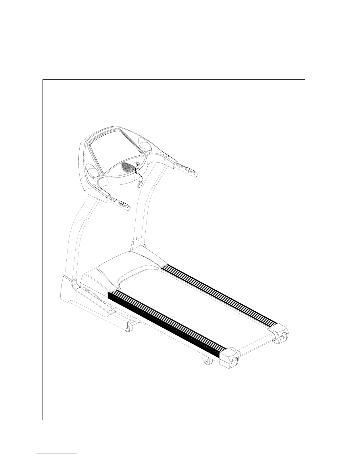
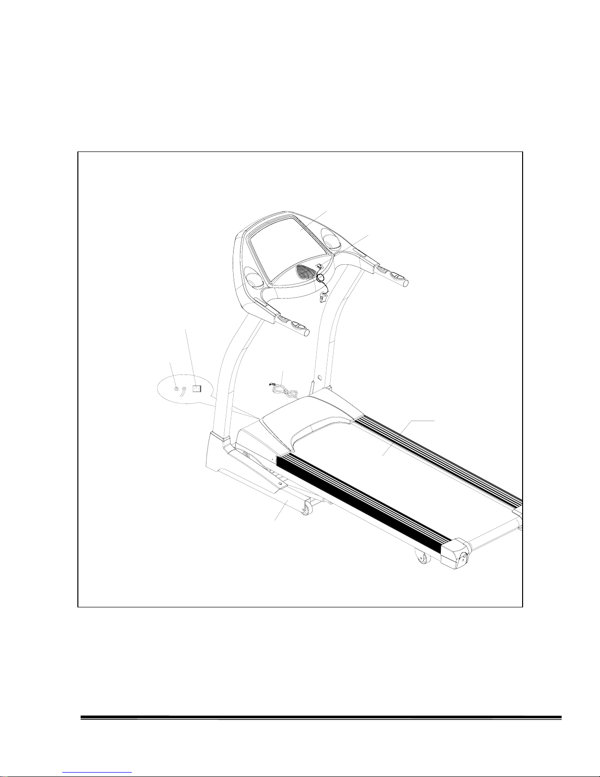
1. OVERVIEW DRAWING
過載保護開關
電源開關
電源線
底座
機台主架
安全插銷/夾子
電子錶
Computer
Safety Key/Clip
Frame
Base
Power Switch
Circuit Breaker
Power
Cord

- 3 -
2. IMPORTANT SAFETY INSTRUCTIONS
When using this product, basic precautions should always be followed, including the
following:
Please read the instruction carefully before starting to use this product.
Danger – To reduce the risk of electric shock:
1. Always unplug this product from the electrical outlet immediately after using and before
cleaning.
Warning – To reduce the risk of burns, fire, electric shock or physical injury:
1. The product should never be left unattended while plugged in. Unplug the product from the
outlet when not in use.
2. Close supervision is necessary when this product is used by or near children, invalids, or
disabled persons.
3. Be sure to use the product only for its intended use as described in this manual. Do not use any
attachment not recommended by the manufacturer in order to avoid any danger or accidents.
4. Never operate the product if it has a damaged cord or plug, if it is not working properly, if it
has been damaged, or dropped into water. Please return the product to the service center of
seller for examination and repair.
5. Do not carry this product by the supply cord or use the cord as a handle.
6. Keep the cord away from hot surfaces or ground.
7. Never operate the product with the air vents blocked. Keep the air vents free of lint, hair, etc.
8. Never drop or insert any objects into any openings.
9. Do not use or operate outdoors.
10. Do not operate where aerosol (spray) products are being used or where oxygen is thin.
11. Before turning the product power off, turn all controls to the off position then remove the plug
from the outlet.
12. Connect the product to a properly grounded outlet only.
13. If the power cord is damaged, be sure to ask the manufacturer for replacement to avoid
accidents .The seller and correlative qualified professionals are as well as eligible.
- 4 -
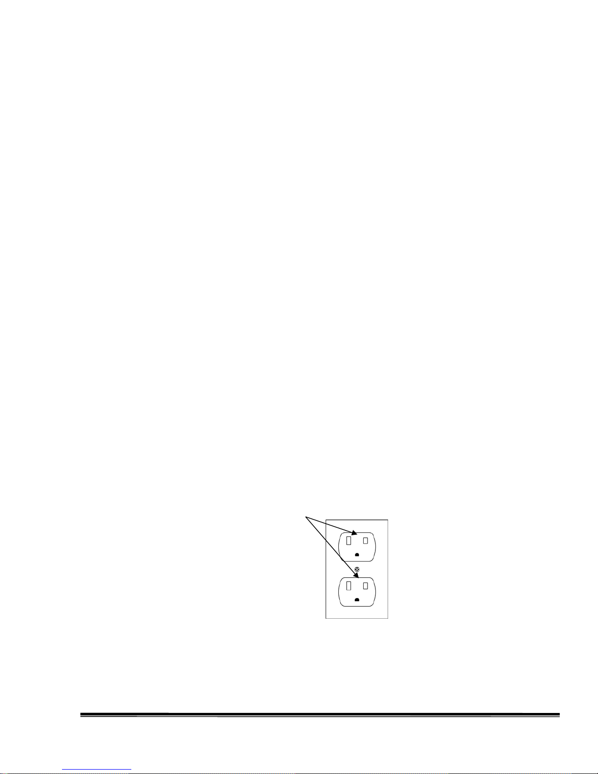
3. GROUNDING INSTRUCTIONS
The products must be grounded first. If malfunction or breakdown occurs, grounding will provide a path
of least resistance for electric current to reduce the risk of electric shock.
The product is equipped with a cord having an equipment-grounding conductor and a grounding plug.
The plug must be plugged into an appropriate outlet that is properly installed and grounded in
accordance with all local codes and ordinances.
Danger – Improper connection of the equipment-grounding conductor can result in a risk of electric
shock. Check with a qualified electrician or serviceman if you are in doubt as to whether the products
are properly grounded. Do not modify the plug provided with the product – if it will not fit the outlet,
have a proper outlet install by a qualified electrician.
The products is for use on nominal 220-240 volt and has a grounding plug that looks like the plug
illustrated in the figure. Make sure that the product is connected to an outlet having the same
configuration as the plug.
There is no need to use any adapter for this product.
Figure
Grounding methods
GROUNDED
OUTLET
- 5 -
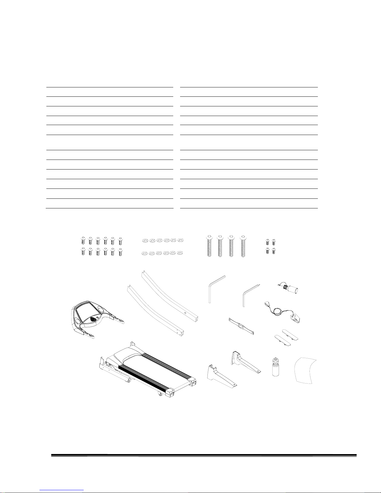
4. PRE-ASSEMBLY CHECK LIST
a
C
D
b
h
g
f
c
A
B
E
F
G
e
d
H
i
j
ITEM Description Qty ITEM Description Qty
A
Computer Console
1 a Allen Bolt M8xP1.25x15 12
B
Frame
1 b Washer Ø8xØ16x1.5t 12
C
Upright (L)
1 c Allen Bolt M8xP1.25x60 4
D Upright (R) 1 d Screw M5xP0.8x18 4
E Cover 2 e SILICON 1
F Decorative Cover (L) 1 f
Allen Wrench+ Screwdriver
5mm(70mmx70mm)
1
G
Decorative Cover (R)
1 g Allen Wrench 6mm (80mm x80mm ) 1
H
Emitter
1 h Safety Key/Clip 1
i Bottle 1
j Towel 1
- 6 -
5. ASSEMBLY STEPS
Two persons are required to finish the assembly
steps.
(Caution!! Please follow the assembly
procedure below to avoid injury. )
1. Attach the control wire-lower section from
the Frame (B) to the guide thread from the
right Upright (D), then pull the control
wire into the Upright , clip it with
protecting ring and fasten it inside of the
Upright. (As shown in the circle of the
picture.)
2. After finish above steps, put the right and
left Upright (C、D) on the Frame. Secure
with Allen Bolt (a) and Washer (h). (As
shown in the picture)
Ps.1. To avoid unexpected accidents, assemble
the treadmill with one or two assistants.
Ps.2 During assembling the support tubes, one
person is needed to hold the support tube to
avoid the falling of the support tube.
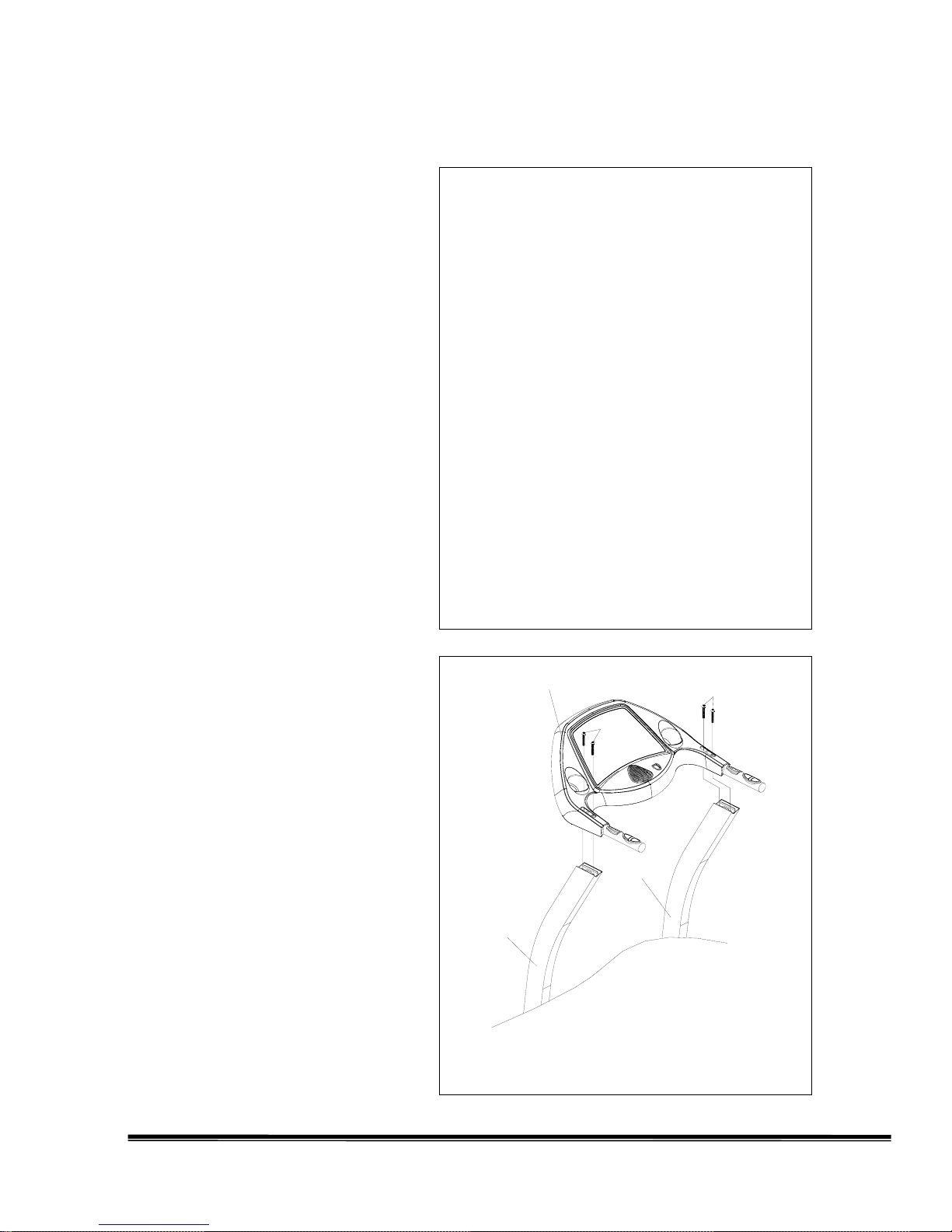
3. After the Uprights are tightened, pull out
the Control W ires which have been
threaded into the Upright to the month of
the Uprights. Then put Computer
Console on the Uprights and connect the
control wire of the Frame with the
control wire of Computer Console (A).
After connecting, tighten them with
Allen Bolt (c) shown in right drawing.
Ps.1. To avoid unexpected accident, always
assemble the treadmill with an assistant, do
not assemble by oneself.
Ps.2. When tighten the screws, make sure not to
damage the control wires in the tube.
A
C
D
c
c
 Loading...