

Page 1

QSI (Q-Star) Electronics
Owner’s Manual
QSI Module
(Installs in Plain Cover Plate)
QSI2 Shown
TABLE OF CONTENTS
INTRODUCTION ..................................... 2
IMPORTANT NOTICE
GENERAL INFORMATION ................ 2
SAFETY ............................................ 2
INSTALLATION
WIRING
TERMINAL CONNECTIONS CHART
QSI1 WIRING ................................... 6
QSI2 WIRING ................................... 7
QSI3 WIRING ................................... 8
FLOMEC APP FOR ANDROID
TEMPERATURE PROBES
INSTALLATION
WIRING .......................................... 11
....................................... 3
................................................... 4
....................... 2
............. 10
.................... 10
............................... 10
(Installs in Display Mount Cover Plate)
MAINTENANCE
REPLACING BATTERY
DISCONNECT POWER
TO METER ...................................... 12
WITHOUT DISPLAY ........................ 12
WITH DISPLAY ............................... 12
SPECIFICATIONS
5
SERVICE
RETURNING PARTS
LIMITED WARRANTY
QSI Module
QSI2 Shown
.................................... 12
................... 12
................................. 15
............................................... 15
....................... 15
........................... 16
920896-05 Rev F04/2018
Page 2

INTRODUCTION
The QSI communications
module is a multiple capability
electronics package. The module
is available with the plain cover
plate or the display mount cover
plate. The QSI module has three
versions (QSI1, QSI2 or QSI3)
available; each with its own mix
of capabilities to better serve the
customer (See Versions below).
• QSI1 is equipped with:
Bluetooth®, **coil/digital pulse
input, pulse output (ow or
energy & scalable), RS485
(Modbus® RTU), temperature
inputs, BTU calculator.
• QSI2 is equipped with:
Bluetooth, **coil/digital
pulse input, pulse output
(ow or energy & scalable),
data logger, temperature
inputs, BTU calculator.
• QSI3 is equipped with:
Bluetooth, **coil/digital pulse
input, pulse output (ow scalable),
data logger, 4-20mA output.
**NOTE The coil/digital input
connections are for use with
equipment other than a QSE meter.
QSE meters automatically provide
coil/digital pulse input via the 10-pin
ribbon cable from the AFE PC board.
If the QSI electronics are used
in a manner not specied by the
manufacturer, the protection provided
by the equipment may be impaired.
GENERAL INFORMATION
QSI electronics are available
mounted to the meter you
ordered or as a kit that adapts the
electronics to other GPI meters.
The QSI electronics converts
the voltage (or pulses) from the
meter into usable information. In
addition to the multiple capabilities
of the module, it also supplies
the display (when installed) with
the information and power it
needs to function as designed.
The QSI module electronics
is powered by customersupplied external power.
SAFETY
• This product is not approved
for use in hazardous locations.
• Be sure O-rings and seals
are kept in good repair.
• When applying power, adhere to
specications in this manual.
• Disconnect external power
before attaching or detaching
input or output wires.
This manual contains information and
meter wiring diagrams for the three
different QSI electronics modules.
IMPORTANT NOTICE
QSI module electronics are very
sensitive to electric noise if operated
within 6 inches of some electric
motors, relays, transformers or
other sources of electronic noise.
2
Page 3
INSTALLATION
CAUTION: Installation near
high electromagnetic elds
and high current elds is not
recommended and may result
in inaccurate readings.
If you ordered your QSI module
electronics with a QSE meter, it
is installed at the factory. If you
ordered your QSI module electronics
separately (i.e. repair part), follow
the instructions below to install
on a QSE meter. If you ordered
your QSI module with one of our
several types of meter adapter kits,
follow the separate instructions
enclosed with the kit to install
the unit. In every case, please
review and thoroughly understand
all manuals and installation
instructions before proceeding.
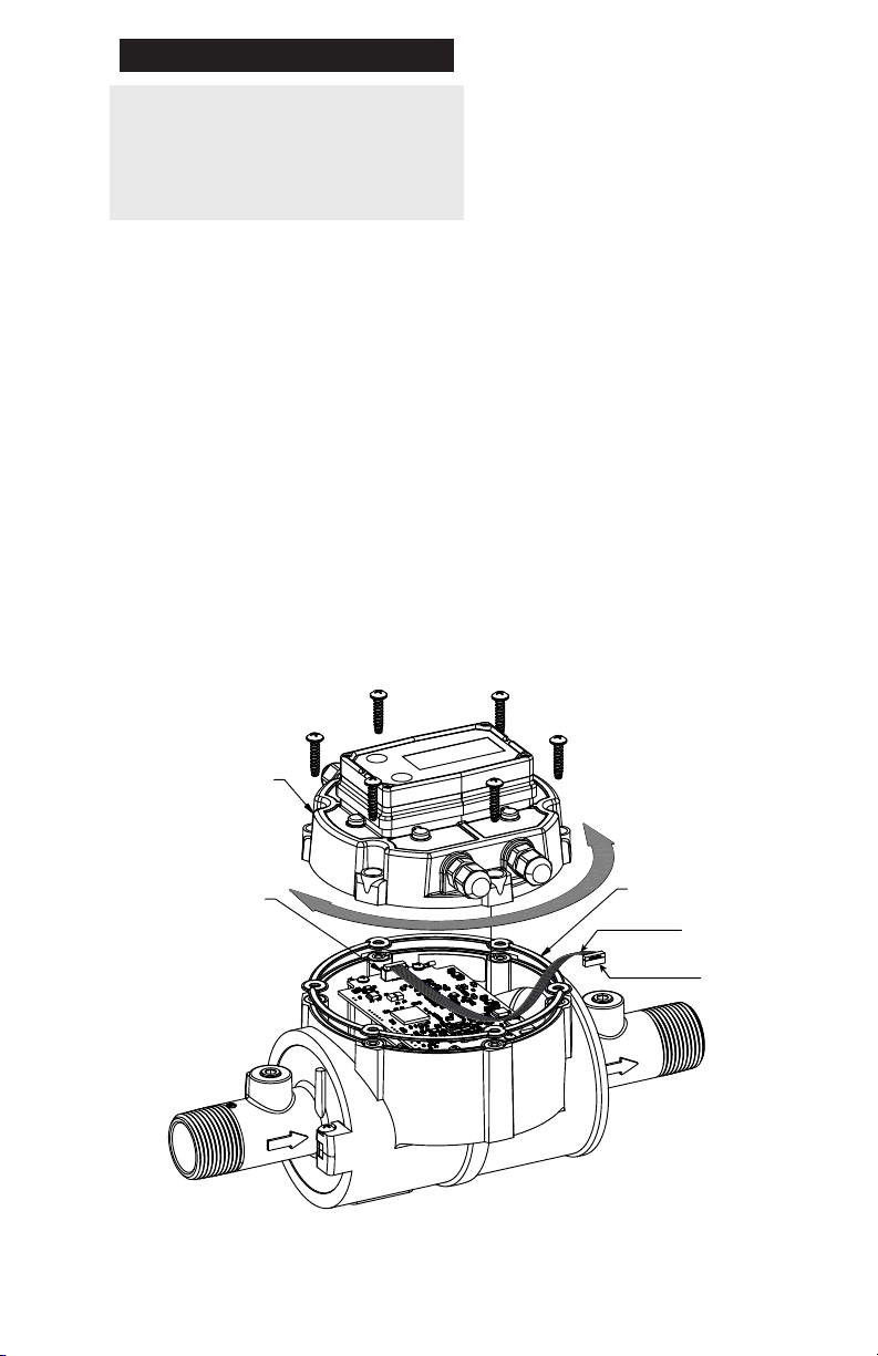
To mount your QSI module (with or
without a display) to a QSE meter:
• Install the cover plate seal.
• Connect the QSI module PC
board connector to the AFE
module PC board connector
inside the meter housing with
the ribbon cable. The ribbon
cable connectors are polarized
and cannot be incorrectly
connected (see Figure 1).
• Install the cover plate with
screw holes aligned.
• Install the (6) cover plate screws
and tighten. Make sure the
cover plate seal is fully seated
before tightening the screws.
A ribbon cable connects the
QSI electronics within the cover
plate to the AFE electronics
within the meter body and allows
180 degrees of movement in
either direction (see Figure 2).
COVER PLATE
(DISPLAY MOUNT
SHOWN)
AFE PC BOARD
CONNECTOR
Figure 1
COVER PLATE
SEAL
RIBBON CABLE
RIBBON CABLE
CONNECTOR
(EACH END)
3
Page 4
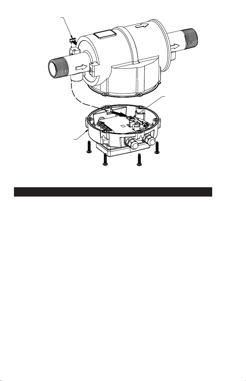
RIBBON CABLE
CONNECTOR
COVER PLATE
(DISPLAY MOUNT
SHOWN)
Figure 2
QSI PC BOARD
CONNECTOR
(RIBBON CABLE)
WIRING
All electronic options are associated
with a matching style of meter cover
plate. This cover plate has four
threaded ports, compatible with PG7
threads, for gaining wiring access
to the electronics inside the cover
plate. The meter is shipped with the
ports environmentally sealed with a
threaded plug and seal. Remove one
or more of these plugs as required to
install the supplied port ttings below.
Each meter is supplied with cable
gland strain reliefs with O-rings and
1/2 NPT adapters with seals for use
in the threaded ports of the meter
cover plate. Select the port ttings
that t your process and replace
the threaded plugs in the cover
plate with the ttings as required.
The threaded plugs installed at the
factory may be left in any unused
cover plate port indenitely.
4
It is recommended that a “removable”
thread-locker (uid, stick, tape,
spray, etc.) be used when installing
the strain reliefs or adapters
into the cover plate ports.
Strain Reliefs:
The cable gland strain reliefs will
accommodate a cable diameter of
0.11 - 0.26 inches (2.79 - 6.6mm)
and provide an environmental
seal around the cable when
the dome-nut is tightened.
NPT Adapters:
The 1/2 NPT adapter ttings are used
for attaching ex conduit to the meter,
for those applications that require
cable runs to be enclosed in conduit.
• Cable to be provided by
customer to accommodate
job requirements. Cable is
not included with meter.
Page 5
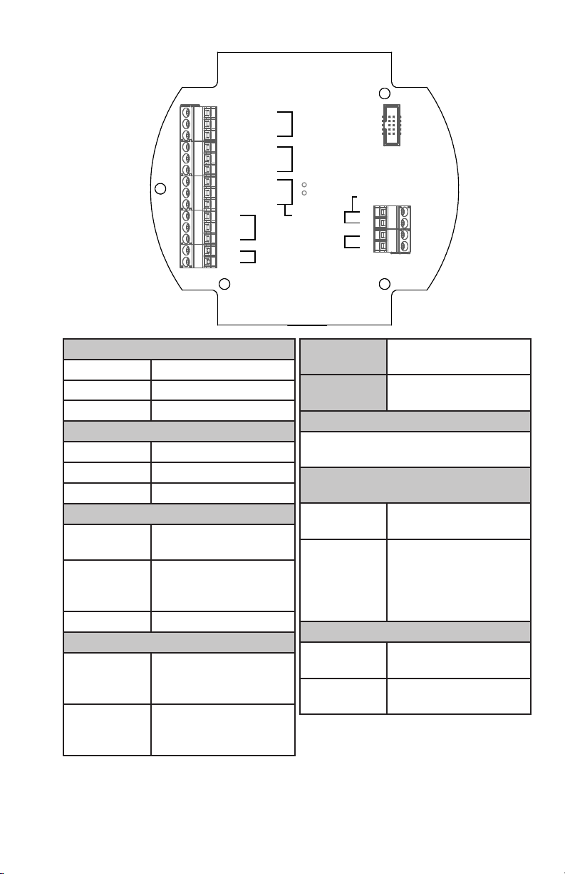
TERMINAL CONNECTIONS CHART
PT100-Red
PT100-White Sensor #1
PT100-Blue
Figure 3
PT100-Red
PT100-White
PT100-Blue
RS-485 +
RS-485 RS-485 GND
+5v
+
-
+
-
Sensor #2
RS-485
Pulse Input
4-20mA
Coil A
Coil B
Power
GPI Sensor
Pulse Output
+
+
TEMP SENSOR
PT100-Red Sensor VCC Output
PT100-White Input High Side
PT100-Blue Input Return
RS-485 (Galvanically Isolated)
RS485 (+) Positive Signal
RS485 (-) Negative Signal
RS485 GND Circuit Ground*
PULSE INPUT
+5V
5VDC output to power
external sensor
Digital Pulse
(+)
Frequency Input,
up to 3kHz
(-) Digital Pulse Return
4-20mA (Galvanically Isolated)
4 to 20mA current
(+)
loop - current in
to transmitter
4 to 20mA current
(-)
loop - current out
of transmitter*
*NOTE: It is not recommended to
connect isolated ground connections
together or to board common.
Coil A
Coil B
Low level sine
wave input
Low level sine
wave input
GPI SENSOR
Ribbon cable connection to
GPI custom sensor designs
PULSE OUTPUT
(Galvanically Isolated)
(-)
Pulse Output
return current*
Pulse Output
frequency output.
(+)
This is a “current
sinking open
collector” output.***
POWER INPUT
(-)
(+)
12-30VAC, 50-60 Hz
or 12-36VDC Input A**
12-30VAC, 50-60 Hz
or 12-36 VDC Input B**
**NOTE: Polarity of voltage for AC/
DC is not important. However an
earth ground isolated power supply is
required to prevent earth ground loop
currents and ground fault conditions.
***NOTE: This output may require an
external pull up resistor if interfacing
equipment does not include one.
5
Page 6

QSI1 WIRING
RTDs
RS-485
RTDs
RS-485
Figure 4
QSI VERSION 1 PC BOARD
RS-485
BTU
10-Pin
Ribbon
Connector
Pulse Out
Power In
Figure 5
6
ISOLATED
PWR SUPPLY
12-30V
AC, 50-60Hz /
12-36VDC
(+) (-)
Ribbon Cable
Power (-)
Power (+)
10-Pin
WIRING DIAGRAM
Inputs: Temp Sensors, GPI Custom Sensor
Outputs: RS-485, Pulse Output
QSI Version 1
GPI
SENSOR
PT100 (Red)
PT100 (White)
PT100 (Blue)
PT100 (Red)
PT100 (White)
PT100 (Blue)
RS485 (+)
RS485 (-)
RS485 (GND)
Pulse Out (+)
Pulse Out (-)
*R
...=120Ω
2
R
2
*Shield
R
NOTE: The QSI does not contain an
2
internal termination resistor. Refer to
Customer Equipment documentation
for proper installation and resistance
value of the external R2 resistor.
Current
Sourcing
Pulse Input
Customer
Equipment
RS485 (+)
RS485 (-)
RS485 (GND)
Page 7

QSI2 WIRING
RTDs
RTDs
Figure 6
QSI VERSION 2 PC BOARD
Pulse In
BTU
10-Pin
Ribbon
Connector
Pulse Out
Power In
Figure 7
ISOLATED
PWR SUPPLY
12-30VAC, 50-60Hz
/ 12-36VDC
(+) (-)
Power (-)
Power (+)
10-Pin
Ribbon Cable
WIRING DIAGRAM
Inputs: Temp Sensors, GPI Custom Sensor
Outputs: Pulse Output
QSI Version 2
GPI
SENSOR
PT100 (Red)
PT100 (White)
PT100 (Blue)
PT100 (Red)
PT100 (White)
PT100 (Blue)
Pulse Out (+)
Pulse Out (-)
Customer
Equipment
Open Collector
Pulse Input
7
Page 8

QSI3 WIRING
4-20mA
Figure 8
QSI VERSION 3 PC BOARD
4-20mA
10-Pin
Ribbon
Connector
Pulse Out
Power In
WIRING DIAGRAM
Inputs: GPI Custom Sensor
Outputs: 4-20mA, Pulse Output
Figure 9
8
ISOLATED
PWR SUPPLY
12-30VAC, 50-60Hz /
12-36VDC
(+) (-)
Power (-)
Power (+)
10-Pin
Ribbon Cable
QSI Version 3
GPI
SENSOR
Pulse Out (+)
Pulse Out (-)
4-20mA (+)
Min. V = 8.5
Max. V = 36
4-20mA (-)
Customer
Equipment
Customer
Equipment
Page 9

WIRING DIAGRAM
QSI Version 3
4-20mA
Inputs: GPI Custom Sensor
Outputs: 4-20mA, Pulse Output
10-Pin
Ribbon Cable
GPI
SENSOR
(+) (-)
Power (-)
Power (+)
ISOLATED
PWR SUPPLY
12-30VAC, 50-60Hz /
12-36VDC
Pulse Out (+)
Pulse Out (-)
Customer
Equipment
4-20mA (+)
Min. V = 8.5
Max. V = 36
4-20mA (-)
Customer
Equipment
ISOLATED
PWR SUPPLY
12-30VAC, 50-60Hz /
12-36VDC
(+) (-)
Power (-)
Power (+)
WIRING DIAGRAM
Customer Equipment without Built-in Power Supply
- 4-20mA Output with Separate Power Supply
QSI Version 3
4-20mA (+)
(Current)
Customer
Equipment
Loop (-)
Figure 10
4-20mA (-)
(Current)
(Current)
Min. V = 8.5
Max. V = 36
Loop (+)
Isolated
Power Supply
(+) (-)
9
Page 10

FLOMEC APP FOR ANDROID
TEMPERATURE PROBES
If you ordered a QSI1 or QSI2
electronic choice with the
temperature probe option, the
correct length probes with cables
are installed near the inlet and
outlet ends of the meter. If you
are installing a temperature probe
retrot kit, you will need to install
the probes on the meter.
The cable used with the probes has
a smaller diameter than the standard
strain reliefs (black), installed on
the meter at the factory, will allow.
Therefore, (2) reduced t strain reliefs
(gray) are included with the probes.
For probe cable entry through the
ports of the meter cover plate (to
wire the system) replace (2) of the
(black) strain reliefs in the cover
plate with these reduced t strain
reliefs. The entire cable length is
used for each probe installation. Both
cables require a matched length.
Typically, a temperature probe
is installed initially in each of
the 1/8” NPT ports of the meter
to calculate the differential
between the two probes, if any.
The differential is captured and
shown in the Android application
as “Temp 1” and “Temp 2” and is
used in the BTU calculations to
ensure an accurate calculation.
For clarity, one probe is considered
PT100 #1 and is connected
to the meter PC board in that
location. It is shown as “Temp
1” in the Android application
The cables are not connected
to the QSI PC board.
Enclosed with your meter is a
stainless steel pipe plug. It will be
used during the set-up process.
INSTALLATION
NOTE: The meter should be
installed in the system return line
for accurate BTU calculations.
Each of the (2) temperature
probes has a 10 ft. cable. The
threaded body of the probe has
1/8” NPT threads to t a standard
1/8” NPT port (see Figure 11).
10
The other probe is then considered
PT100 #2 and is connected
to the meter PC board in that
location. It is shown as “Temp
2” in the Android application.
To perform the differential check,
the probe installed in the 1/8” NPT
port near the meter outlet end
should be considered PT100 #1.
The probe installed in the 1/8”
NPT port near the meter inlet end
should be considered PT100 #2.
See Figures 5 and 7 for
wiring diagrams.
Page 11

After wiring the probes to the
correct terminal of the PC board,
perform the differential check.
NOTE: Use NSF approved thread
sealant on the male threads of the
probes when installing in either the
meter ports or system port. Failure
to do will void the NSF certication.
After performing the differential
check, remove the PT100 #2 probe
near the inlet end of the meter
and install the pipe plug, received
with your meter, in the open meter
port. Install the removed probe
in the system supply line.
NOTE: Use NSF approved thread
sealant on the male threads of
the pipe plug when installing it in
the meter port. Failure to do so
will void the NSF certication.
TEMPERATURE SENSOR ON OUTLET END OF MET ER
(PT100 #1)
During normal system operation,
probe PT100 #1 is installed at the
meter outlet end and probe PT100
#2 is installed in the system supply
line. Accurate system BTU usage is
calculated between the (2) probes.
The excess cable from the PT100
#1 probe (on the meter) to the
cover plate may be coiled and
secured using plastic quick ties.
WIRING
See Figures 5 and 7 for
wiring diagrams.
WATER RETURN
Figure 11
TEMPERATURE SENSOR ON SUPPLY PIPE
(PT100 #2)
WATER DELIVERY
11
Page 12

MAINTENANCE
Check cable-entry seals periodically.
Tighten and/or apply sealant if
needed. This is especially important
in environments containing
heavy concentrations of dust,
oil mist, or other residue.
Check all wiring connections
occasionally for oxidation or
corrosion. Clean and re-seat if
such conditions are noted.
• Remove and replace the coin cell
battery (CR2032) on the back
side of PC board (see Figure 14).
NOTE: To maintain certications, a
UL approved battery must be used.
• Reverse the procedure to
reassemble the cover plate to the
meter. Make sure the cover plate
seal is seated before tightening
the (6) cover plate screws.
WITH DISPLAY
If necessary, check and re-seat any
connections that may have been
subjected to strain (during rework
or construction, for example).
REPLACING BATTERY
The QSI2 and QSI3 communications
module has a 3V lithium coin
cell battery installed on the PC
board. In case of power failure
the battery functions as power
backup to maintain the internal
system time. Any QSI2 or QSI3
feature that uses a time reference
as part of its functionality will
be immediately accurate to
the current time when power is
restored. To Replace Battery:
DISCONNECT POWER TO METER
WITHOUT DISPLAY
• Remove (6) screws retaining the
cover plate to the meter body
and lift the cover plate free of
the meter body (see Figure 12).
• Flip the cover plate over
and remove (4) screws
retaining the PC board
assembly (see Figure 13).
On units with a display, only the
display needs to be removed to
replace the coin cell battery. The
battery is accessible through
the opening where the display
is installed (see Figure 15).
• Remove (4) screws retaining
the display to the cover plate.
Lift the display straight up to
disconnect the 10-pin bridge
connector. The bridge connector
could disengage from either
socket connector (display or
PCB assembly) or both.
• Remove and replace the
coin cell battery (CR2032).
NOTE: To maintain certications, a
UL approved battery must be used.
• Reverse the procedure to
reassemble the display to the
meter. Make sure the display
seal is seated before tightening
the (4) display screws.
12
Page 13

BATTERY (CR2032)
BATTERY (CR2032)
SCREWS (4)
BATTERY (CR2032)
Figure 12
Figure 13
DISPLAY
SEAL
BRIDGE
CONNECTOR
Figure 14
Figure 15
13
Page 14

SPECIFICATIONS
MECHANICAL
Cover Plate
Port Threads
Port Strain
Relief
Grip Range
Operation
Temperature
Ambient Air
Operation
Temp
Port Conduit
Adapter
Operation
Temperature
Ambient Air
Operation
Temp
Storage
Temperature
(with Display)
Recommended
Cable
Female 1/2-20 UNF-2B
(Compatible with
PG7 thread)
Hubble PG7
0.11”-0.26”
(2.79 - 6.6mm)
+32°F to +140°F
(0°C to +60°C)
0°F to +140°F
(-18°C to +60°C)
GPI PG7 x 1/2
in. NPT Male
+32°F to +140°F
(0°C to +60°C)
0°F to +140°F
(-18°C to +60°C)
40°F to +158°F
(-40°C to +70°C)
Belden #9501
(2-Conductor w/Drain
Wire, Shielded)
POWER SUPPLY
Min. 12 VDC
or 12 VAC, 5060 Hz (voltages
below 12V will
Voltage
Requirement
result in meter
accuracy issues)
Max. 36 VDC or
30 VAC, 50-60 Hz
(higher voltage
may damage unit)
Battery
Backup (QSI2,
QSI3 Only)
Coin cell lithium, 3V
(CR2032)
UL APPROVED
MAX POWER CONSUMPTION
QSE Meter
with QSI
14
170mA
4 watts @ 24VDC
6 watts @ 36VDC
ELECTRICAL
Pollution
Degree
Installation
Category
2
1
Altitude 2000m Max.
Indoor use only
OUTPUTS & COMMUNICATION
QSI Version 1:
Bluetooth
Coil/Digital Pulse Input**
Pulse Output
RS485
Temperature Inputs
BTU Calculator
QSI Version 2:
Bluetooth
Coil/Digital Pulse Input**
Pulse Output
Data Logger
Temperature Inputs
BTU Calculator
QSI Version 3:
Bluetooth
Coil/Digital Pulse Input**
Pulse Output
Data Logger
4-20mA output
**NOTE The coil/digital input
connections are for use with
equipment other than a QSE meter.
QSE meters automatically provide
coil/digital pulse input via the 10-pin
ribbon cable from the AFE PC board.
Page 15

SERVICE
The Waste Electrical and Electronic
Equipment (WEEE) directive
(2002/96/EC) was approved by the
European Parliament and the Council
of the European Union in 2003. This
symbol indicates that this product
contains electrical and electronic
equipment that may include bat-
teries, printed circuit boards, liquid
crystal displays or other components that may be subject
to local disposal regulations at your location. Please
understand those regulations and dispose of this product
in a responsible manner.
For warranty consideration, contact
your local distributor. If you need
further assistance, contact the GPI
Customer Service Department at:
ou will need to:
Y
• Provide information from
the decal on your meter.
• Receive a Return
Authorization number.
• Flush any uid from the meter
before shipping to the factory.
RETURNING PARTS
Please contact the factory before
returning any parts. It may be
possible to diagnose the trouble
and identify needed parts in a
telephone call. GPI can also
inform you of any special handling
requirements you will need to
follow covering the transportation
and handling of equipment
which has been used to transfer
hazardous or ammable liquids.
RoHS Compliant (2011/65/EU)
This product is in compliance with
the RoHS Directive of the European
Parliament and of the Council on
the Restriction of the Use of Certain
Hazardous Substances in Electrical
and Electronic Equipment.
CAUTION: Do not return equipment
without specic authority from the
GPI Customer Service Department.
Due to strict regulations governing
transportation, handling, and
disposal of hazardous or ammable
liquids, GPI will not accept
equipment for rework unless it is
completely free of liquid residue.
15
Page 16

© 2018 Great Plains Industries, Inc., All Rights Reserved.
Great Plains Industries, Inc.
920896-05 Rev F04/2018
 Loading...