

Page 1

Q09 Display
Owner’s Manual
(Shown on 1 inch NPT QSE Meter)
Q09 Display
TABLE OF CONTENTS
INTRODUCTION ..................................... 1
IMPORTANT NOTICE ....................... 2
SAFETY ............................................ 2
INSTALLATION ....................................... 2
OPERATION ........................................... 4
Display .............................................. 4
Batch And Cumulative Totals ........... 4
CALIBRATION ........................................ 4
Factory Calibration ........................... 4
Field Calibration ............................... 5
USER CONFIGURATION ........................ 6
Changing Conguration Settings ..... 6
K-Factor Entry Field Calibration ....... 6
MAINTENANCE ...................................... 6
SPECIFICATIONS ................................... 7
SERVICE ................................................. 8
Returning Parts ................................ 8
LIMITED WARRANTY ........................... 12
INTRODUCTION
The Q09 display is specically
designed to operate with the
electronics housed within the cover
plate. The display is mounted on a
specialized cover plate containing
other electronics and together they
make up the total Q09 electronics
package. The electronics in the
cover plate (QSB [not available
as adapter kit]) or (QSI1, QSI2 or
QSI3) when externally powered,
provides correctly adjusted power
to the display via a 10 pin bridge
connector. Information on the
operation, capabilities and wiring of
the electronics within the cover plate
that is mated to your Q09 display
is contained in its own dedicated
manual (QSB, QSI1, QSI2, QSI3).
920896-03 Rev B03/2018
Page 2

The display microprocessor
electronics have extremely low power
requirements and high data retention
capabilities in both RAM and ROM.
Information is clearly displayed on
a large 6-digit LCD readout with
two-point oating decimal for totals
from .01 to 999,999. All operations
are easily accessed with the two
buttons on the front panel.
The Q09 display is available mounted
to the meter you ordered or as a
kit that adapts the electronics to
other GPI meters. The electronics
inside the cover plate converts
the voltage (or pulses) from the
meter into usable information. This
information, along with power, is
supplied to the display that translates
the information into calibrated ow
units shown on the display’s readout.
The display is a precision measuring
instrument and should be handled
as such. Refer to the Specications
Section to conrm required features.
IMPORTANT NOTICE
Q09 displays are very sensitive to
electric noise if operated within 6
inches of some electric motors,
relays, transformers or other
sources of electronic noise.
If the Q09 Display is used in
a manner not specied by the
manufacturer, the protection provided
by the equipment may be impaired.
SAFETY
• This product is not approved
for use in hazardous locations.
• Be sure O-rings and seals
are kept in good repair.
• When applying power, adhere to
specications in this manual.
• Disconnect external power
before attaching or detaching
input or output wires.
WARNING: Product should
never be operated outside its
published specications for
temperature or pressure. See
specications for your model.
CAUTION: Installation near
high electromagnetic elds
and high current elds is not
recommended and may result
in inaccurate readings.
INSTALLATION
If you ordered your Q09 display
with a meter, it is installed at the
factory. If you ordered your Q09
display separately from a meter (i.e.
repair part), follow the instructions
below to install on a QSE meter. If
you ordered your Q09 display with
one of our several types of meter
adapter kits, follow the separate
instructions enclosed with the kit to
install the unit. In every case, please
review and thoroughly understand
all manuals and installation
instructions before proceeding.
• Make sure the seal is seated
in its groove on the bottom of
the display (see Figure 1).
• Insert the long pins of the
10 pin bridge connector
about half-way into the 10
pin PC board connector.
• Then, align the 10 pin connector
on the display with the short pins
on the 10 pin bridge connector
and engage pins using gentle
force until the display is seated
on the cover plate (see Figure 2).
2
Page 3
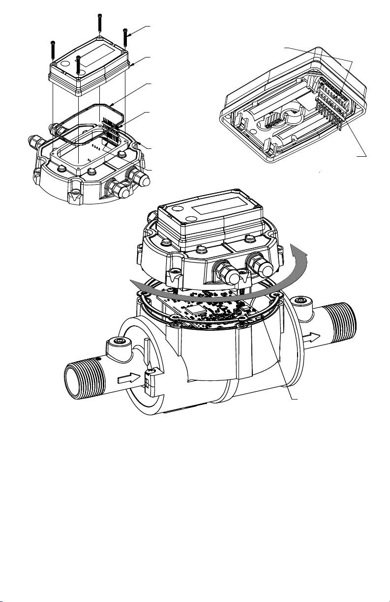
(4) SCREWS
10 PIN SOCKET
Figure 1
DISPLAY
SEAL
10 PIN BRIDGE
CONNECTOR,
SHORT PINS UP
COVER PLATE
10 PIN PC BOARD
CONNECTOR
CONNECTER
10 PIN BRIDGE
CONNECTOR
Figure 2
• When the display is seated
Figure 3
on the cover plate, the pins
are fully engaged. Secure the
display to the cover plate with
the four screws at the corners
of the faceplate. Make sure
the seal is fully seated before
tightening the screws.
COVER PLATE
SEAL
QSE meters are designed to
measure ow in only one direction.
If the display is upside down in
your installation, remove the six
screws retaining the cover plate to
the meter, turn the cover plate with
display as required and reinstall the
screws. A ribbon cable connects the
electronics within the cover plate to
electronics within the meter body
and allows 180 degrees of movement
in either direction. Make sure the
cover plate seal is fully seated before
tightening the screws (see Figure 3).
3
Page 4

DISPLAY
OPERATION
When uid is owing through
the meter, a small propeller
icon is highlighted.
All operations are reected in the
LCD readout. The large center
digits indicate amounts, where
smaller words or “icons” located
above and below indicate specic
information regarding totals, ow,
calibration and units of measure.
Activate the Meter: When power is
supplied to the meter, the display
automatically becomes active, is
on continuously and always ready
to perform. It remains active until
meter power is disconnected.
BATCH AND CUMULATIVE TOTALS
The display maintains two totals.
The Cumulative Total provides
continuous measurement and
cannot be manually reset. The Batch
Total can be reset to measure ow
during a single use. The Cumulative
Total is labeled TOTAL 1, Batch
Total is labeled TOTAL 2 BATCH.
When the Cumulative Total reaches
a display reading of 999,999 the
display will highlight an X10 icon.
This indicates to the operator that a
zero must be added to the 6 digits
shown. When the next rollover
occurs, the display will highlight
an X100 icon. This indicates to
the operator that two zeros must
be added to the 6 digits shown.
Press the DISPLAY button
briey to switch between the
TOTAL 1, TOTAL 2 BATCH and
FLOWRATE. When TOTAL 2 BATCH
is displayed, you can hold the
DISPLAY button for 3 seconds to
reset the Batch Total to zero.
4
Flowrate Feature: To use this feature,
press and release DISPLAY button
until FLOWRATE icon appears.
The factory set time base will be
highlighted to the right of FLOWRATE
(M = minutes, H = hours, D = days).
When FLOWRATE is invoked, the
display will be indicating rate of ow.
CALIBRATION
FACTORY CALIBRATION
All Q09 Displays
All calibration units are visible to the
user as icons on the top line of the
display, above the numeric digits.
All units are congured with a
“factory” calibration. Both gallons
and litres are available (“GL” or “LT”
will be displayed). While holding
the CALIBRATE button, briey
press DISPLAY to toggle between
gallons and litres. This factory
calibration (indicated with FAC) is
permanently programmed into the
display and is not user adjustable.
NOTE: Your display may have other
units of measure programmed into
it. If so, holding the CALIBRATE
button and momentarily pressing the
DISPLAY button will toggle through
all factory set units. Other possible
units are: IGL (imperial gallon), QT
(quart), CF (cubic feet), CM (cubic
meter), BL (42 gal. barrel), CC
(cubic centimeter) or OZ (ounce).
Switching between different units will
not corrupt the Total’s contents. For
example, in GL mode, the display
totalizes 10.00 gallons, if the user
switches to LT mode, the display will
Page 5

read 37.85 litres (the same volume,
different unit). The “eld” calibration
may be set by the user, and can be
changed or modied at any time
using the calibration procedure
described in the Field Calibration
Section. Totals or owrate derived
from the eld calibration are invoked
when the FAC icon is no longer
visible on the top line of the display.
Factory calibration settings are
programmed into each display
during manufacturing, using water
at 70° F (21° C). Readings using
the Factory Calibration (FAC) may
not be accurate in some situations.
For example: Under extreme
temperature conditions, nonstandard plumbing congurations
or with uids other than water.
FIELD CALIBRATION
If the meter is suspected of being
incorrect, eld calibration is a method
of adjusting the meter K-factor to
compensate for error causing factors.
The method of eld calibration is
dependent on the electronics that
is mated with your Q09 display.
NOTE: Q09 displays not mated to
QSI electronics will use the manual
entry Correction Factor Method
outlined below.
The manual entry method of eld
calibration outlined below is disabled
when the Q09 display is mated with
QSI electronics. The QSI electronics
becomes the controlling element
that manages the manual calibration
entries for the display. This eld
calibration method is available in
the QSI Android Application noted
in the QSI owner’s manual.
Q09 Displays Not Mated
to QSI Electronics
A manual entry method using the
buttons on the Q09 display is used.
This method adjusts the K-factor by
percentages to match the display
volume with actual volume.
Calibration Using Display
(Correction Factor Method)
Field Calibration and Factory
Calibration were outlined previously
in the Calibration Section.
1. To eld calibrate, press and
hold the CALIBRATE and
DISPLAY buttons for about 3
seconds until you see FLdCAL.
Release both buttons and you
will see CF - 00.0. You are now
in the eld calibration mode
and values from -99.9% to
+99.9% can be entered.
2. The +/– position appears either
as an “underscore” character
for positive, or as a “hyphen”
character for negative. The
DISPLAY button selects the
position and the CALIBRATE
button toggles this character.
3. The DISPLAY button can then
be pushed to select the numeric
positions. Press the CALIBRATE
button to scroll from 0 to 9. Enter
the percentage of change you
want the display to correct. When
satised with the value, press
both CALIBRATE and DISPLAY
buttons simultaneously. CALEnd
will be displayed and unit will go
back to normal operation, less
the FAC (factory calibration) icon.
4. All enabled units-of-measure
remain visible and selectable –
the entered correction will be
applied to all enabled units.
5. To return to factory calibration
(FAC), press and hold both
CALIBRATE and DISPLAY
buttons for about 3 seconds
until FAcCAL is displayed. Then
release buttons. The unit should
return to normal operation
and FAC icon is visible.
5
Page 6

USER CONFIGURATION
The Q09 display has been
programmed with many features,
most of which can be enabled by the
end user by way of a conguration
process. By disabling “unnecessary”
features, day-to-day owmeter
operation can be greatly simplied,
making the unit easier to use.
There are several features that are
disabled by default when shipping
standard meters. (For example,
K-Factor Entry Field Calibration,
described below.) For more
advanced users, it may be desirable
to enable ALL possible features.
User congurable features include:
• Totalizers/Modes Enabled
(Cumulative Total, Batch 2
Total, Flowrate Mode).
• Flowrate Timebase
(Minute, Hour, Day).
• Factory Calibration Curve Units
Enabled – Gallons, Litres, Imperial
Gallons, Quarts, Ounces, Cubic
Feet, Cubic Centimeters, Cubic
Meters or Barrels (42 Gal).
• Dispense/Display or K-Factor
Entry Calibration.
CHANGING CONFIGURATION SETTINGS
Q09 Displays Not Mated
to QSI Electronics
NOTE: Q09 displays not mated to
QSI electronics can use the manual
entry method outlined below.
The manual entry method of
changing conguration settings
outlined below is disabled when
the Q09 display is mated with QSI
electronics. The QSI electronics
becomes the controlling element that
manages the manual conguration
entries. This conguration setting
method is available in the QSI
Android Application noted in
the QSI owner’s manual.
Access to the conguration process
is restricted for security until a
“password” is entered. Contact
your distributor or GPI to get the
password and instructions to unlock
and reset conguration settings.
This information is also available at
www.FLOMEC.net. Congurations
are entered and stored as six-digit
“codes” where each digit represents
a setting for one of the conguration
options. New conguration settings
are stored in the display’s long-term
memory and will not be lost either in
OFF mode or during electrical failure.
K-FACTOR ENTRY FIELD CALIBRATION
Presently all displays are
programmed with three different
eld calibration methods, only one
of which is active, the “correction
factor” calibration procedure
described above. It is possible
to activate “K-Factor entry” or
“dispense/display” eld calibration
by changing conguration settings.
Contact your distributor or GPI to get
the correct password, conguration
code and instructions for this
calibration method. This information
is also available on the GPI Web site.
MAINTENANCE
The display is virtually maintenancefree. However, it is important
to keep the display clean and
free of contaminants.
6
Page 7

SPECIFICATIONS
STANDARD FEATURES
• 2 Totalizing Registers
• 1 Factory Calibration Curve
• 1 Field Calibration Curve
• Rate of Flow Feature
• Flowrate Time Base in Minutes
INPUT PULSE RATE
Minimum Pulse In: DC
Minimum
Coil Input:
Maximum Raw: 1,000 Hz
Minimum: .01 pulses/unit
Maximum:
FIELD CALIBRATION
Minimum: -99.9%
Maximum: +99.9%
READOUT TOTALS
Min. Display: 0.01
Max. Display: 999,999 (x100)
TEMPERATURES
Operational:
Storage:
Ambient Air
Operation
Temperature
10 Hz
K-FACTOR
999,999
pulses/unit
CORRECTION
+0° to +140° F
(-18° to +60° C)
-40° to +158° F
(-40° to +70° C)
0°F to +140°F
(-18°C to +60°C)
INTERNAL POWER
SUPPLY TO DISPLAY
5 VDC provided
by a 10 pin
bridge connector
from cover plate
Voltage
Requirement:
Pollution
Degree
Installation
Category
electronics.
External power to
meter is required
to provide
necessary internal
power to display.
ELECTRICAL
2
1
Altitude 2000m Max.
Indoor use only
7
Page 8

SERVICE
The Waste Electrical and Electronic
Equipment (WEEE) directive
(2002/96/EC) was approved by the
European Parliament and the Council
of the European Union in 2003. This
symbol indicates that this product
contains electrical and electronic
equipment that may include bat-
teries, printed circuit boards, liquid
crystal displays or other components that may be subject
to local disposal regulations at your location. Please
understand those regulations and dispose of this product
in a responsible manner.
For warranty consideration, contact
your local distributor. If you need
further assistance, contact the GPI
Customer Service Department at:
o obtain prompt, efcient
T
service, always be prepared with
the following information:
1. The model number of
your display electronics.
2. The serial number and
manufacturing date code
of the FLOMEC® meter the
display is attached to.
3. Specic information about part
numbers and descriptions.
For warranty work always be
prepared with your original sales slip
or other evidence of purchase date.
RETURNING PARTS
Please contact the factory before
returning any parts. It may be
possible to diagnose the trouble
and identify needed parts in a
telephone call. GPI can also
inform you of any special handling
requirements you will need to
follow covering the transportation
and handling of equipment
which has been used to transfer
hazardous or ammable liquids.
RoHS Compliant (2011/65/EU)
This product is in compliance with
the RoHS Directive of the European
Parliament and of the Council on
the Restriction of the Use of Certain
Hazardous Substances in Electrical
and Electronic Equipment.
CAUTION: Do not return equipment
without specic authority from the
GPI Customer Service Department.
Due to strict regulations governing
transportation, handling, and
disposal of hazardous or ammable
liquids, GPI will not accept
equipment for rework unless it is
completely free of liquid residue..
8
Page 9

91011
Page 10

Page 11

Page 12

© 2018 Great Plains Industries, Inc., All Rights Reserved.
Great Plains Industries, Inc.
920896-03 Rev B03/2018
 Loading...