

Page 1
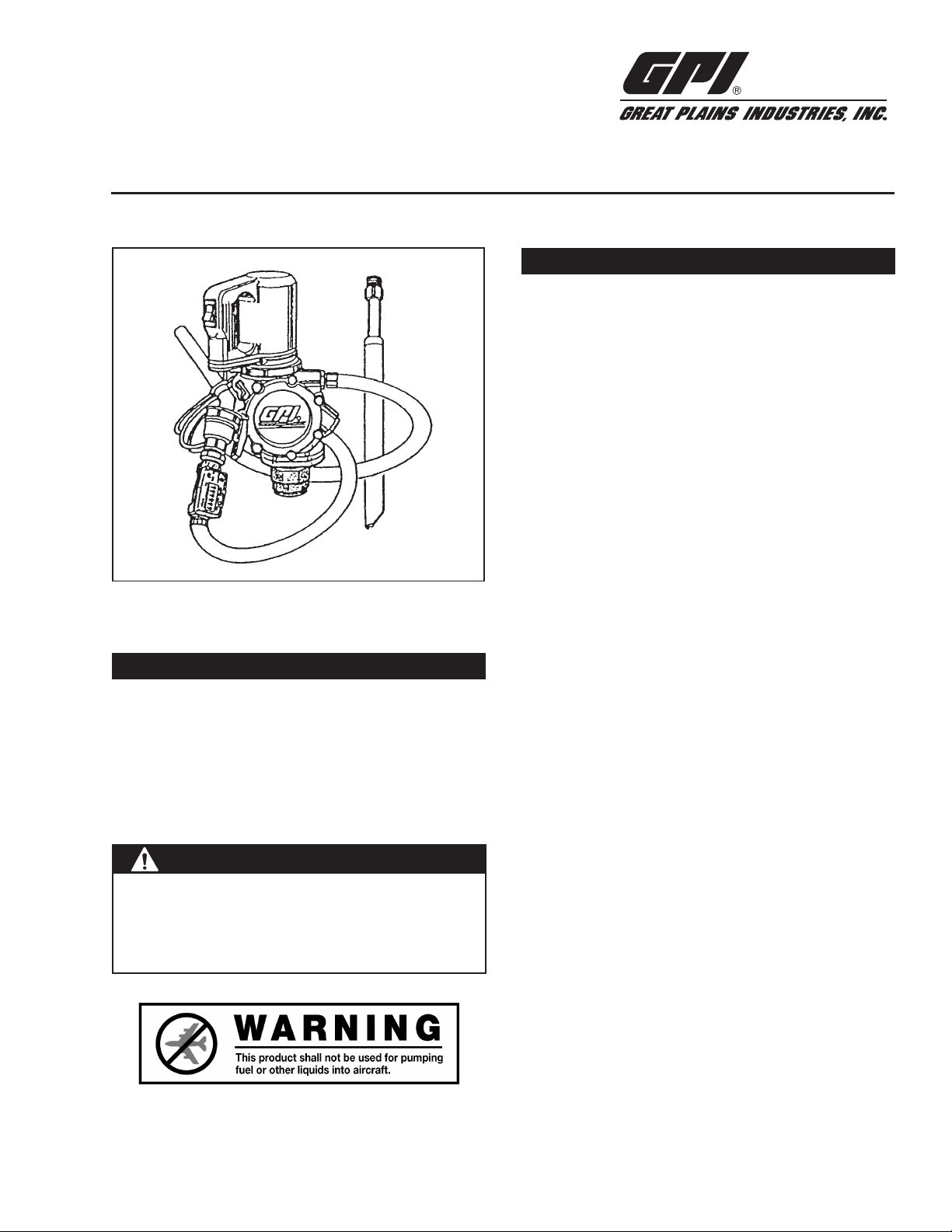
VP12 High Viscosity Piston Pump
5252 Ea st 3 6th Str eet Nor th
Wich ita , KS US A 67 220- 320 5
TEL: 31 6-68 6-7 361
FAX: 316- 686 -674 6
“A Gr ea t P la ins Ve nt ure s Sub si dia ry”
www.gpi.net
1-8 00 -835-0113
Owner’s Manual
INSTALLATION INSTRUCTIONS
Unpack and inspect all components. Inspect for any damage
which may have occurred during shipping. If shipping damage
is found, a claim should be filed with the carrier as soon as
possible. Remove the two protective plugs from the inlet and
outlet ports of the pump.
Install Bung Adapter
1. Apply sealant (furnished) to the threads on one end of the
bung adapter bushing.
2. Install onto tank or container and tighten snugly with a
pipe wrench.
Install Suction Pipe
1. If using the adjustable suction pipe, apply thread sealer
to threaded end of the suction pipe.
2. Insert gasket into the union nut on the bung adapter.
GENERAL INFORMATION
To the owner:
Congratulations on your purchase of the VP12 Pump. Your
pump is manufactured in accordance with the highest standards. Following the operation and maintenance procedures
provided in this manual will help you achieve years of dependable performance and trouble-free operation. Please read
this manual carefully and keep for future use.
!!! W A R N I N G !!!
The GPI VP12 pump is for use with non-flammable fluids
only. The pump should not be used for gasoline, diesel,
other fuels, herbicides or chemicals. The VP12 has been
designed for use with viscous petroleum products.
Pump is not for use with flammable liquids.
3. Insert the strainer into the suction pipe and thread suction
pipe into the housing.
A suction pipe can also be created using a 1 inch pipe with 1
in. NPT threads on one end. Proper length can be determined
by inserting the threaded end through the bung adapter and
down to the bottom of the tank. Mark the pipe even with top
of bung adapter. Remove the pipe and cut off the pipe on
the mark.
NOTE: Be sure that pipe material is compatible with fluid.
1. Clean pipe of all foreign material and apply sealant to the
threads.
2. Insert gasket into the union nut on the bung adapter and
thread pipe into base of pump.
3. Tighten snugly with a pipe wrench.
Install Pump and Suction Pipe Onto Tank
1. If using the adjustable suction pipe, extend suction pipe
to full length.
2. Insert suction pipe, attached to pump, into the tank carefully. The suction pipe will telescope back to the proper
length needed to rest on the bottom of the tank.
3. Thread union nut onto the bung adapter bushing and
tighten union nut snugly with a pipe wrench.
1
Rev. A 921641-501/06
Page 2

4. If using a self-made suction pipe, insert the suction pipe
attached to the pump into the tank. Thread the union nut
onto the bung adapter bushing and tighten the union nut
snugly with a pipe wrench.
MAINTENANCE / STORAGE
!!! C A U T I O N !!!
Install Hose, Nozzle and Optional Meter
1. Apply thread sealer to all threads.
2. Thread the hose adapter into the pump outlet port.
3. Install hose into the hose adapter.
4. Install optional meter. (If using an electronic meter, thread
meter onto the discharge-end of hose.)
NOTE: Flow direction is marked by an arrow on meter
housing.
5. Thread the optional nipple into the meter and then install
the nozzle onto nipple.
NOTE: If optional meter is not used, simply thread hose into
inlet end of nozzle.
OPERATING PROCEDURES
Turning On the Pump
1. The “ On / Off ” switch is located on the handle of the
motor assembly.
2. To prevent motor and pump damage, do not operate
pump in By-Pass mode (i.e., recirculation with nozzle
closed) for more than 10 minutes.
3. Do not leave the pump running with fluids. “Dry running” causes damage to piston seals and other pump
components.
4. Inspect pump wiring to ensure it is correctly attached
to the battery and properly grounded. To avoid electrical shock, use extra care when connecting the pump
system to the battery or power supply.
5. Pump is for use with viscous petroleum products only.
Pump is not for use with flammable liquids.
Proper maintenance and storage will ensure a long
pump life. Failure to follow the recommended cleaning
and storage procedures will increase pump failures
and void warranty.
It is very important that the following procedures are followed
to assure the reliable, trouble-free operation you expect from
your GPI pump. If the pump system is not going to be used
for an extended period of time, it is important that the pump
be correctly flushed clean of all residue. These extra steps
help avoid down time!
Daily Care
It is mandatory that the pump system always be kept full of
liquids. Do not allow liquids to “dry” inside the pump. If this
should happen, DO NOT START THE PUMP. Refer to “Liquid
Has Dried Inside Pump” section for additional instructions.
Each time the pump is used, visually check for leakage under
the pump housing. A small drain hole will relieve any fluid which
may by-pass around the pistons. If even a small amount of
liquid is found, new seals are needed on the pistons. Refer to
Assembly/Disassembly section for instructions.
End of Season Care
If the pump has been used for any fluid other than oil, flush
the complete system as follows:
1. Remove pump from tank.
2. Insert inlet portion of pump into sufficient water supply to
allow pump to run at least 10 to 15 minutes.
NOTE: It may be easier to remove the suction pipe and attach
a smaller inlet pipe.
These steps will allow the complete pump system to be thoroughly rinsed. While flushing, open and close nozzle 15 to 20
times. This forces the dampener to open and close, insuring
self-priming and clean internal components at next usage.
NOTE: If the optional electronic meter is installed, the meter
reading will change when flushed with the pump system.
Flushing the meter is also essential to clean sticky fluids
from rotor and housing.
3. Do not leave water inside the pump. Water deposits may
form, causing the pump system to “freeze-up.” Refer to
“Liquid Has Dried Inside Pump” section before turning
the pump on.
4. Fill the entire system with a light motor oil by inserting
inlet portion of pump into 3 or 4 quarts of oil.
5. Turn pump on, open the ball valve and allow oil to recirculate
back into the container. While the pump is running, open
and close the ball valve several times. Allow the pump to
recirculate for a few minutes.
2
Page 3
6. When completed, turn off pump and close the ball valve
nozzle. Store pump indoors.
4. Remove screws on motor cover and disconnect motor
wires from switch.
7. Check the camshaft assembly and the two bearings (top
and bottom of camshaft) for proper grease.
NOTE: See “Assembly/Disassembly” section for proper
removal of camshaft.
8. If no grease is found, lubricate camshaft, bearings and
all seals with a high-temperature lithium based grease.
Check every 50 hours of operation thereafter.
Liquid Has Dried Inside Pump
!!! W A R N I N G !!!
If liquid has dried inside of the pump, DO NOT start
the motor.
1. Remove motor assembly and both end covers from housing.
2. Apply a penetrating lubricant such as WD-40® onto the
pistons and piston liners in the housing. Allow to soak for
several minutes.
3. After soaking, use a protective cloth and pliers or other
gripping tool to carefully rotate the camshaft back and
forth. This will free-up pistons prior to operating.
4. Remove and clean the poppet assembly following the
instructions in the “Assembly/Disassembly” section.
5. Remove the two spacers and four valve cage assemblies
from housing, noting relative positions.
6. Check the valve balls to be sure they are not sticking.
5. Replace with new motor by reversing the procedure.
Reduction Gearcase Removal / Replacement
1. Remove the four screws on the bottom of motor.
2. Slip reduction gear assembly off motor shaft.
3. When reassembling, do not overtorque (10 lb.-in. maximum).
Switch Removal / Replacement
1. Remove the six screws from one side of plastic motor
cover.
2. Disconnect the wires from the old switch and remove.
Replace with new switch by reversing procedure.
3. When re-installing screws, tighten until snug; do not
overtorque.
Camshaft & Bearing Mount Assembly
Removal / Replacement
1. Remove motor then remove the four screws from the
bearing mount assembly.
2. Carefully slide bearing mount assembly from the camshaft assembly, noting the location of thrust washer for
replacement. Check all bearings for wear and proper
lubrication.
NOTE: The bottom bearing is part of the housing and is not
easily removed. Replacement of housing may be necessary if bearing is worn.
7. Reassemble above components only after they are free,
clean and working properly.
ASSEMBLY / DISASSEMBLY
When disassembling your pump, carefully inspect all components for wear or damage. Replace as necessary to assure
the reliable, trouble-free operation from your GPI pump. Refer
to the list of Replacement Parts, Kits and Accessories found
on the Illustrated Parts Drawing page.
Motor Removal / Replacement
1. Loosen V-clamp retainer until T-bolt slips out of yoke.
2. Remove motor assembly and seal by sliding motor straight
away from the pump housing. Be careful not to damage
the seal.
3. Replace with new motor by first removing reduction gear
(see following section).
Replace camshaft & bearing mount assembly as follows:
1. Lubricate camshaft, piston rod, all bearings, and lip seal
in bearing mount assembly with high temperature lithium
grease.
2. Align camshaft with bottom bearing, thrust washer and
piston rod.
3. Rotate until camshaft slips into place, resting in the bottom
bearing and in the slot of the piston rod.
4. Replace the bearing mount assembly onto the camshaft,
carefully aligning the bearing mount assembly to prevent
damage to the seal in the assembly.
5. Continue carefully working the bearing mount assembly
until it slips onto the spline of the camshaft.
6. Replace the four screws retaining the bearing mount assembly and tighten to a snug fit (10-12 lb.-in torque). Do
not overtighten.
3
Page 4

Poppet Assembly Removal / Inspection
NOTE: If the pump pulsates heavily during operation, clean-
ing of the dampener may be necessary. Some pulsation
of the pump is normal.
1. Carefully remove poppet valve/plug, seal, and spring from
the pump housing.
NOTE: The poppet valve/plug retains the spring and support
in a compressed state, so take care not to lose these
components when the plug is loosened.
Pistons Removal / Replacement
Removal and replacement of the pistons is somewhat involved,
requiring a ring compressor (supplied with the Piston Assembly Kit). Damage to piston liners will require replacement
of the housing.
1. To remove pistons, remove the screws on each side of
the piston rod.
2. After removing both screws, pull the piston assemblies
out of their respective sides.
2. Remove the dampener from the housing with a slight
back-and-forth motion. Wash the entire poppet assembly
in warm soapy water.
NOTE: The dampener should not be taken apart.
3. While washing the dampener, push in and rotate the
plug to be sure the spring and plug are free and clean of
residue.
4. Rinse and reinstall the entire poppet assembly. Tighten
to a snug fit.
Valve Gage Assemblies Removal / Replacement
1. Remove seven bolts and washers on each side of the end
covers. Note the position of the valve cage assemblies
and the two spacers for proper replacement.
2. Carefully remove the valve cage assemblies and inspect
for damage or residue.
NOTE: The valve cage assemblies should not be taken
apart.
NOTE: Remove pistons only in this manner. If an attempt
is made to pull the piston through the opposite side,
or to remove the piston rod without first removing both
pistons, one piston may become lodged in the center of
the housing.
3. After removing the pistons, remove the camshaft by following the steps described in the “Camshaft & Bearing
Mount Assembly Removal/Replacement” section. The
piston rod may then be removed from the housing.
4. Inspect piston seals and piston rod for wear or damage.
If either is evident, replace them.
NOTE: Reverse this procedure to install piston rod, pistons
and valve cage assemblies. Refer to Illustrated Parts
Drawing for correct positioning of parts.
4
Page 5

TROUBLESHOOTING
SYMPTOM PROBABLE CAUSE CORRECTIVE ACTION
A. LOW FLOWRATE 1. Leakage Check under pump for leakage through drain hole in bottom of
pump housing assembly.
2. Poppet spring is weak Check and/or clean poppet assembly. Replace if necessary.
Do not disassemble the dampener.
3. Suction pipe clogged or Check suction pipe for leaks or clogs. Clean or replace as
damaged necessary.
4. Poor connections or Check for low battery voltage.
low voltage
5. Damaged seal Check for worn piston seal.
B. PUMP FAILS TO 1. System air leak Check for air leak in suction side of system and around all
PRIME fittings, connections and suction pipe.
2. Sticking valve cage Check valve cage assemblies for sticking.
assemblies
3. Poppet assembly is Check and/or clean poppet assembly. Replace components,
damaged or binding as necessary.
4. Failed gearbox Check gearbox on the motor to see if it is turning.
C. MOTOR OVERHEATS, 1. Poppet assembly is Check and/or clean poppet assembly. Replace components,
STALLS WHEN damaged or binding as necessary. Do not disassemble the dampener.
NOZZLE IS CLOSED,
OR PULSATES 2. Suction pipe clogged or Check suction pipe for leaks or clogs. Clean or replace as
EXCESSIVELY damaged needed.
3. Inlet screen clogged Check inlet screen for clogs.
4. Duty cycle too long Avoid excessive operating time. Duty cycle is 30 minutes ON, 30
minutes OFF.
D. MOTOR WON’T RUN 1. Poor connections Check battery connections.
WHEN THE SWITCH
IS TURNED ON 2. Electrical connections Check for blown fuse (replace with 20 amp fuse) or dead
faulty battery. Check for faulty switch or motor. Replace if burned out.
Contact factory for assistance troubleshooting switch or motor
problems.
5
Page 6

ILLUSTRATED PARTS DRAWING
2
38
4
6
10
34
14
1312
3
24
35
15
1
21
22
23
36
9
9A
16
11
25
26
27
20
28
29
30
31
Item No.
No. Part No. Description Req’d.
2A
5
7
8
32
33
15
17
18
3A
19
20
1 115002-1 Housing Assembly .......................... 1
115015-1 Hose Adapter (Outlet port of
Housing) ..................................... 1
2 115008-1 12 VDC Motor Assembly.................1
2 902002-91 Switch (not shown) ............................ 1
3 115003-1 End Cover ....................................... 1
3A 115003-2 End Cover .......................................1
4 901001-91 Seal, Motor Adapter ........................ 1
5 906001-69 V-Clamp Retainer (order 115548-1) ... 1
6 904003-7 Screw, 1/4-20 x 1/2" .......................4
7 115010-1 Bearing Mount Assembly ................1
8 901001-90 Seal, Bearing Mount .......................1
9 115009-1 Camshaft Assembly ........................ 1
9A 906001-87 Bearing ............................................ 1
9A 904003-10 Snap Ring .......................................1
10 906001-68 Bearing (order 115522-1 Kit ) .............. 1
11 904003-5 Washer, Thrust ................................ 1
12 901001-92 Seal, End Cover ..............................2
13 904003-9 Hex Cap Screw, 1/4-20 x 7/8" ........ 2
14 904003-11 Washer ............................................2
15 115012-1 Piston Assembly .............................2
16 115031-1 Piston Rod ......................................1
17 115021-1 Valve Cage Assembly ..................... 4
18 115099-1 Spacer .............................................2
19 904001-21 Washer (order 904003-49 ) ...............14
20 904001-30 Screw, 1/4-20 x 1"
(order 904003-49 ) ....................... 14
21 115011-1 Dampener Assembly ....................... 1
22 115035-1 Spring, Poppet ................................ 1
23 901001-94 Seal, Bypass Plug ........................... 1
24 115044-2 Plug, Dampener .............................. 1
25 901001-93 Seal, Lower Cover ........................... 1
26 904003-1 Nut ..................................................6
27* 115108-1 Lower Cover .................................... 1
28* 115013-1 Union Ring ......................................1
29* 114030-1 Inlet Fitting (Internal By-Pass) ......... 1
30 114029-1 Gasket ............................................. 1
31 115097-2 Bushing, Tank Bung Adapter ..........1
32 115037-1 Back-up Ring ..................................2
33 115037-2 Back-up Ring ..................................2
34 110188-1 Hose, 1" x 12' Buna-N .................... 1
35 113900-9511 03N31GM EDM (optional) ............... 1
36 110098-1 Nipple, 1 in. Plastic (optional) .........1
37 110107-2 Ball Valve Nozzle .............................1
38 110100-1 22 to 44 in. Adj. Suction Pipe .........1
115005-3 Strainer ............................................ 1
39 115016-1 Power Cord Assembly (not shown) ... 1
* Order 115018-2 Assembly below.
37
Accessories and Kits
115018-2 Lower Cover Assembly (Internal By-Pass) – Includes Item No’s. 25, 27, 28 and 29 (1 each).
115519-1 Wet Seal Kit (Pump) – Includes Item No’s. 23 and 25 (2 each) and 12.
115522-1 Bearing Mount Assembly Kit – Includes Item No’s. 4, 7 and 8 (1 each).
115523-1 Piston Assembly Kit – Includes Item No’s. 13, 14 and 15 (2 each).
115525-1 Motor Kit – Includes 12 Volt DC Motor (115006-1) and Gear Box (906001-71).
115526-1 Motor Cover Kit – Includes 115014-2 and 115014-1 Covers.
116000-1 Calibration Container – 5 Gallon (not shown).
6
Page 7

SPECIFICATIONS PARTS AND SERVICE
Pump is designed for use with viscous petroleum products.
DO NOT use with flammable liquids.
1. Lightweight, corrosion-resistant, durable, molded Nylon
housing with built-in handle and convenient spin collar.
2. 1 in. NPT inlet and outlet ports.
3. 1" x 12' Buna-N hose, ball valve nozzle, and adjustable
plastic suction pipe.
4. VP12, 12 Volt DC model, comes with 20' - 14 ga. power
cord with 20 Amp fuse and battery clips.
5. 20 psi maximum working pressure.
6. Typical “Duty Cycle” of 30 minutes ON, 30 minutes OFF.
The more viscous the fluid (cold/thick) the shorter the duty
cycle. Use with fluids up to 2,000 centipoise viscosity.
Flowrange up to 8 GPM (30 LPM).
7. The VP12 will pump viscous petroleum products at temperatures within the range of +40°F to +104°F.
8. Shipping weight (approx.): 25 lbs.
For warranty consideration, parts, or other service information, please contact your local distributor. If you need further
assistance, contact the GPI Customer Service Department in
Wichita, Kansas, during normal business hours.
A toll free number is provided for your convenience.
1-800-835-0113
To obtain prompt, efficient service, always be prepared with
the following information:
1. The model number of your pump.
2. The serial number or manufacturing date code of your
pump.
3. Part descriptions and numbers.
Part information can be found on the Illustrated Parts Drawing page.
For warranty work, always be prepared with your original sales
slip or other evidence of purchase date.
Please contact GPI before returning any parts. It may be
possible to diagnose the trouble and identify needed parts
in a telephone call. GPI can also inform you of any special
requirements you will need to follow for shipping fuel dispensing equipment.
CAUTION: Do not return the pump or parts without author-
ity from the Customer Service Department. Due to strict
government regulations, GPI cannot accept parts unless
they have been drained and cleaned.
7
Page 8

5252 East 36th Street North
Wichita, KS USA 67220-3205
TEL: 316-686-7361
FAX: 316-686-6746
“A Gr e a t P l a i n s V e n t u r e s S u b s i d i a r y ”
www.gpi.net
1-800-835-0113
Limited Warranty Policy
Great Plains Industries, Inc. 5252 E. 36th Street North, Wichita, KS USA 67220-3205, hereby provides a limited warranty against defects in material
and workmanship on all products manufactured by Great Plains Industries, Inc. This product includes a 2 year warranty. Manufacturer’s sole obligation
under the foregoing warranties will be limited to either, at Manufacturer’s option, replacing or repairing defective Goods (subject to limitations hereinafter
provided) or refunding the purchase price for such Goods theretofore paid by the Buyer, and Buyer’s exclusive remedy for breach of any such warranties
will be enforcement of such obligations of Manufacturer. The warranty shall extend to the purchaser of this product and to any person to whom such
product is transferred during the warranty period.
The warranty period shall begin on the date of manufacture or on the date of purchase with an original sales receipt. This warranty shall not apply if:
A. the product has been altered or modified outside the warrantor’s duly appointed representative;
B. the product has been subjected to neglect, misuse, abuse or damage or has been installed or operated other than in accordance with the
manufacturer’s operating instructions.
To make a claim against this warranty, contact the GPI Customer Service Department at 316-686-7361 or 800-835-0113. Or by mail at:
The company shall, notify the customer to either send the product, transportation prepaid, to the company at its office in Wichita, Kansas, or to a
duly authorized service center. The company shall perform all obligations imposed on it by the terms of this warranty within 60 days of receipt of the
defective product.
GREAT PLAINS INDUSTRIES, INC., EXCLUDES LIABILITY UNDER THIS WARRANTY FOR DIRECT, INDIRECT, INCIDENTAL AND CONSEQUENTIAL
DAMAGES INCURRED IN THE USE OR LOSS OF USE OF THE PRODUCT WARRANTED HEREUNDER.
The company herewith expressly disclaims any warranty of merchantability or fitness for any particular purpose other than for which it was designed.
This warranty gives you specific rights and you may also have other rights which vary from U.S. state to U.S. state.
Note: In compliance with MAGNUSON MOSS CONSUMER WARRANTY ACT – Part 702 (governs the resale availability of the warranty terms).
Great Plains Industries, Inc.
5252 E. 36th St. North
Wichita, KS, USA 67220-3205
GPI and the electric gear pump are registered trademarks of
Great Plains Industries, Inc.
© 2006 GREAT PLAINS INDUSTRIES, INC., Wichita, KS
Printed in U.S.A.
Rev. A 921641-501/06
 Loading...