

Page 1
ENGLISH
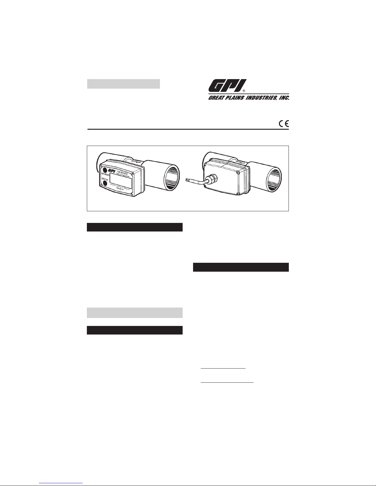
IMPORTANT NOTICE
Use TM Series meters with water and other
chemicals compatible with wetted components. Do not use to meter fuel or incompatible
chemicals. TM Series meters are available with
either a computer for local electronic display, or
a conditioned signal output module to provide a
digital signal to customer interfacing equipment.
TM Series meters with computer display measure in gallons or litres. Refer to the Calibration
Section for details.
TM Series Electronic Water Meters
User Manual
Rev. B 920786-02
04/13
TABLE OF CONTENTS
English ...........................................................1
Español ..........................................................8
Deutsch .......................................................15
Italiano .........................................................22
Français .......................................................29
SAVE THESE INSTRUCTIONS
These meters are not legal for trade applications.
TM Series meters are very sensitive to electric
noise if operated within 1 to 2 inches of some
electric motors or other sources of electronic
noise.
INSTALLATION
Connections
Install your meter in-line either horizontally or
vertically or at the end of the hose adjacent to
the nozzle. Installation to metal connections is
not recommended. Install as follows:
1. Plan to install turbine with a minimum straight
pipe length as follows:
•
Upstream from the turbine, allow a mini-
mum straight pipe length of 10 times the
internal diameter of the turbine.
•
Downstream from the turbine, allow a
minimum straight pipe length of 5 times
the internal diameter of the turbine.
2. For Spigot (Pipe) End use only primer and
solvents approved for PVC gluing.
For NPT and BSP Fittings wrap all connec-
tions with 3 to 4 wraps of thread tape (optional
to use pipe thread sealant). Make sure the
tape does not intrude into the flow path.
TM Meter with Computer Display TM Digital Pulse Meter
www.GlobalTestSupply.com
Find Quality Products Online at: sales@GlobalTestSupply.com
Page 2

2
3. Attach meter with arrow pointed in the direction of fluid flow.
4. For NPT and BSP Fittings - Hand tighten
the meter at the housing ends. Do not use
a wrench or similar tool to tighten. This can
damage the housing.
OPEN COLLECTOR SIGNAL OUTPUT
Wiring Diagram 1
+9 to 35 volt DC
Open Collector
Signal
3
2
1
4
Red
White
Black
Common
(Ground)
Terminal
Block
Customer
Interfacing
Equipment
The terminal block is identified as follows:
Pin #1 6 volt square wave (not used)
Pin #2 +9 to 35 volt DC Input
Pin #3 Common Ground
Pin #4 Open Collector signal Output
Resistor
To protect against leakage, seal all pipe
threads with an appropriate sealing compound. Make sure the sealing compound
does not intrude into the flow path.
NOTE: If connecting to new male pipe threads,
burrs and curls can adversely affect accuracy. Correct the problem prior to turbine
installation.
NOTE: Do not over tighten the flange bolts. This
may cause the gasket to be compressed
into the flow stream and may decrease the
accuracy of the meter.
Compatibility of this product’s material
and the process fluid and/or environment
should be considered prior to putting into
service.
WARNING
Product should never be operated outside
its published specifications for temperature
or pressure. See specifications for your
model.
WARNING
Make sure flow and pressure have been
eliminated from process pipe prior to
installing or removing product.
WARNING
Always use appropriate thread sealant or
flange gaskets when connecting product
to
process piping.
WARNING
Installation near high electromagnetic fields
and high current fields is not recommended
and may result in inaccurate readings.
CAUTION
CAUTION
www.GlobalTestSupply.com
Find Quality Products Online at: sales@GlobalTestSupply.com
Page 3

3
Conditioned Signal Output
Module Wiring
This conditioned signal output module can be
wired to provide an open collector signal output
or 6-volt square wave output.
Open Collector Signal Output
To achieve an open collector signal output,
reference Wiring Diagram 1. The terminal block
is located on the back side of the module. The
module is factory assembled for open collector signal output. Please provide the (820 ohm
minimum) resistor.
Ten feet (3 m) of cable is provided with the
module. Trim it to desired length or extend it as
necessary. Distances up to 5,000 feet (1,524 m)
can be achieved for open collector signal output.
Square Wave Output
To achieve square wave output, reference Wiring Diagram 2 and use an Electronic Digital
Meter Battery Kit (sold separately) for battery
power. The terminal block and battery location
are located on the back side of the module.
Access as follows:
1. Remove the four Phillips-head screws from
the front of the module and lift the module
from the turbine.
2. To change terminal block connections,
loosen the appropriate screws. Reconnect
the wires in the proper positions and tighten
the screws.
3. Install the batteries. Make sure the positive
post is in the correct position.
4. Position the module on the turbine housing.
To avoid moisture damage, make sure the
seal is fully seated. Tighten the four screws
on the front of the module.
Ten feet (3 m) of cable is provided with the
module. Trim the cable to desired length or
extend it as necessary.
Verify Meter Accuracy
Before using, check the meter’s accuracy and
verify calibration.
1. Make sure there is no air in the system by
starting the flow until it runs steadily. Then,
stop or divert the flow using a valve or nozzle.
SQUARE WAVE OUTPUT
Wiring Diagram 2
3
2
1
4
White
Black
Common
(Ground)
Terminal
Block
Customer
Interfacing
Equipment
6 volt Square
Wave Signal
The terminal block is identified as follows:
Pin #1 6 volt square wave
Pin #2 +9 to 35 volt DC Input (not used)
Pin #3 Common Ground
Pin #4 Open Collector signal Output (not used)
www.GlobalTestSupply.com
Find Quality Products Online at: sales@GlobalTestSupply.com
Page 4

4
2. Meter an exact known volume into an accurate container. For best results, meter with
one continuous full stream.
3. Check the volume against the display or
recording equipment. If the amount metered
is accurate, further calibration is not necessary. If not, refer to the Calibration Section
for further instructions.
OPERATION
Computer Display –
Batch and Cumulative Totals
The computer maintains two totals. The Cumulative Total provides continuous measurement and
cannot be manually reset. The Batch Total can
be reset to measure flow during a single use.
The Cumulative Total is labeled TOTAL 1, Batch
Total is labeled TOTAL 2 BATCH.
When the Cumulative Total reaches a display
reading of 999,999 the computer will highlight
an X10 icon. This indicates to the operator that
a zero must be added to the 6 digits shown.
When the next rollover occurs, the computer
will highlight an X100 icon. This indicates to
the operator that two zeros must be added to
the 6 digits shown.
Press the DISPLAY button briefly to switch
between the TOTAL 1, TOTAL 2 BATCH and
FLOWRATE. Press DISPLAY briefly to display
the TOTAL 2 BATCH. Hold the DISPLAY button
for 3 seconds to reset the Batch Total to zero.
When fluid is flowing through the meter, a small
propeller icon is highlighted.
NOTE: Totalization counts total units without
differentiating between gallons, litres or field
calibrated units.
Flowrate Feature
To use this feature, press and release DISPLAY
button until FLOWRATE icon appears. The
factory set time base will be highlighted to the
right of FLOWRATE (M = minutes, H = hours,
D = days). When FLOWRATE is invoked, the
display will be indicating rate of flow.
Activate the Meter
Computer is on continuously and always ready
to perform. The computer is powered by field
replaceable batteries. When display becomes
dim, faded or the low battery message appears
(see below), the batteries need to be replaced.
Reference the Maintenance Section for details.
Factory and Field Calibration
All calibration information is visible to the user
as icons on the top line of the display, above
the numeric digits.
All units are configured with a “factory” calibration. Both gallons and litres are available (“GL”
or “LT” will be displayed). While holding the
CALIBRATE button, briefly press DISPLAY to
toggle between gallons and litres. This factory
calibration (indicated with FAC) is permanently
programmed into the computer and is not user
adjustable.
NOTE: Your computer may have other units of
measure programmed into it. If so, holding
the CALIBRATE button and momentarily
pressing the DISPLAY button will toggle
through all factory set units. Other possible
units are: IGL (imperial gallon), QT (quart), CF
(cubic feet), CM (cubic meter), BL (42 gal.
barrel), CC (cubic centimeter) or OZ (ounce).
Switching between different units will not corrupt
the Total’s contents. For example, in GL mode,
the computer totalizes 10.00 gallons, if the user
switches to LT mode, the display will read 37.85
litres (the same volume, different unit).
The “field” calibration may be set by the user,
and can be changed or modified at any time
using the calibration procedure described in the
Calibration Section. Totals or flowrate derived
from the field calibration are invoked when the
FAC icon is no longer visible on the top line of
the display.
CALIBRATION
Verify Accuracy Before
Beginning Field Calibration
For the most accurate results, dispense at a
flowrate which best simulates your actual operating conditions. Avoid “dribbling” more fluid or
repeatedly starting and stopping the flow. This
can result in less accurate calibrations.
Make sure you meet the meter’s minimum
flowrate requirements:
www.GlobalTestSupply.com
Find Quality Products Online at: sales@GlobalTestSupply.com
Page 5

5
TM Series Meters
½ inch meter 1 GPM (3.8 LPM)
¾ inch meter 2 GPM (7.5 LPM)
1 inch meter 5 GPM (18.8 LPM)
1 ½ inch meter 10 GPM (37.5 LPM)
2 inch meter 20 GPM (75 LPM)
The use of a uniformly dependable, accurate
calibration container is recommended for the
most accurate results. Due to high flowrate, it
is strongly recommended that calibration be
completed with a combination of volume and
weight using fine resolution scales.
For best results, the meter should be installed
and purged of air before field calibration.
Field Calibration with
Computer Display
Field Calibration and Factory Calibration are
defined in the Operation Section. Factory
calibration settings are programmed into each
computer during manufacturing, using water
at 70° F (21° C). Readings using the Factory
Calibration (FAC) may not be accurate in some
situations, for example, under extreme temperature conditions, non-standard plumbing
configurations or with fluids other than water.
Field Calibration Procedures
(Correction Factor Method)
1. To calibrate, press and hold the CALIBRATE
and DISPLAY buttons for about 3 seconds
until you see FLdCAL. Release both buttons
and you will see CF - 00.0. You are now in
the field calibration mode and values from
-99.9% to +99.9% can be entered.
2. The
+
/– position appears either as an “underscore” character for plus, or as a “hyphen”
character for minus. The DISPLAY button
selects the position and the CALIBRATE
button toggles this character.
3. The DISPLAY button can then be pushed
to select the numeric positions. Press the
CALIBRATE button to scroll from 0 to 9.
Enter the percentage of change you want
the display to correct. When satisfied with
the value, press both CALIBRATE and DISPLAY buttons simultaneously. CALEnd will
be displayed and unit will go back to normal
operation, less the FAC (factory calibration)
icon.
4. All enabled units-of-measure remain visible
and selectable – the entered correction will
be applied to all enabled units.
5. To return to factory calibration (FAC), press
and hold both CALIBRATE and DISPLAY
buttons for about 3 seconds until FAcCAL
is displayed. Then release buttons. Unit
should return to normal operation and FAC
icon is visible.
Calibration with Conditioned
Signal Output Module
The K-factor of your meter appears on the
calibration report as the number of pulses per
gallon. The factor is determined during production using water at 70° F (21° C). This K-factor
may be used for “single point” calibration and
provide acceptable accuracy. However, readings
may not be accurate when using this calibration method in some situations. For example,
extreme temperature conditions, non-standard
plumbing configurations or with fluids other
than water.
MAINTENANCE
Proper handling and care will extend the life and
service of the meter.
Turbine Rotor
The meter is virtually maintenance-free. However, it is important the rotor moves freely. Keep
the meter clean and free of contaminants.
If the rotor does not turn freely, apply a penetrating lubricant on the rotor, shaft and bearings.
Remove any debris or deposits from the rotor
using a soft brush or small probe. Be careful
not to damage the turbine rotor or supports.
Blowing compressed air through the turbine assembly could damage the rotor.
CAUTION
CAUTION
CAUTION
Do not allow liquids to dry inside the turbine.
Handle the rotor carefully. Small scratches
or nicks can affect accuracy.
www.GlobalTestSupply.com
Find Quality Products Online at: sales@GlobalTestSupply.com
Page 6

6
Battery Replacement
The computer display is powered by two 3-volt
lithium batteries which may be replaced while the
meter is installed. When batteries are removed or
lose power, the batch and cumula tive totals and
the field and factory calibrations are re tained.
(Battery) – Avoid mechanical or electrical
abuse. Batteries may explode or cause
burns, if disassembled, crushed or exposed
to fire or temperatures in excess of 212°F
(100°C). Do not short circuit or install with
incorrect polarity. DO NOT INCINERATE.
Batteries should ONLY be replaced with
P/N 113520-1 Kit (Includes two each
P/N 902004-2 Batteries). Do not mix old
with new. Do not use other brands or
technologies.
Open battery cells should be disposed
of in accordance with local regulations.
Lithium batteries are best disposed of as a
non-hazardous waste when fully or mostly
discharged. EPA does not list or exempt
Lithium as a hazardous waste. If waste
lithium batteries are still fully charged
or only partially discharged, they can be
considered a reactive hazardous waste
because of unconsumed lithium remaining
in the battery. Such batteries may qualify
as “Universal Waste” in many jurisdictions
within the U.S. and thus can be shipped for
disposal or recycling in accordance with
Universal Waste requirements.
CAUTION
WARNING
If the display becomes dim, blank or the low
battery message appears (see below), replace
the batteries as follows:
1. Remove the four Phillips-head screws from
the face of the meter and lift the faceplate
from the turbine.
2. Remove the old batteries and clean any
corrosion from the terminals.
3. Install new batteries. Make sure the positive
post is in the correct position.
4. When the batteries are replaced, the faceplate will power ON. Check the display to
ensure normal functions have resumed
before assembling again.
5. Reseat batteries, if necessary, and position the faceplate on the turbine housing.
To avoid moisture damage, make sure the
seal is fully seated. Tighten the four screws
on the faceplate.
SPECIFICATIONS
Inlet and Outlet:
Spigot (Pipe) End Models:
TM050/TM050-P ½ inch Schd. 80,
Spigot (Pipe)
TM075/TM075-P ¾ inch Schd. 80,
Spigot (Pipe)
TM100/TM100-P 1 inch Schd. 80,
Spigot (Pipe)
TM150/TM150-P 1 ½ inch Schd. 80,
Spigot (Pipe)
TM200/TM200-P 2 inch Schd. 80,
Spigot (Pipe)
NPT Models:
TM050-N/TM050-N-P ½ inch NPT
TM075-N/TM075-N-P ¾ inch NPT
TM100-N/TM100-N-P 1 inch NPT
TM150-N/TM150-N-P 1 ½ inch NPT
TM200-N/TM200-N-P 2 inch NPT
BSP Models:
TM100-B/TM100-B-P 1 in. BSP
TM150-B/TM150-B-P 1 ½ in. BSP
TM200-B/TM200-B-P 2 in. BSP
Design Type: Turbine
Wetted Components:
Housing: PVC
Journal Bearings: Ceramic
Shaft: Tungsten Carbide
Rotor and Supports: PVDF
Retaining Washer: Stainless Steel
Max. Working Pressure:
225 PSIG @ 73° F
BSP: 150 PSIG @ 73° F
www.GlobalTestSupply.com
Find Quality Products Online at: sales@GlobalTestSupply.com
Page 7

7
U.S. Measurement
Unit of Measure: Gallon
Flow Range:
½ inch 1 - 10 GPM
¾ inch 2 - 20 GPM
1 inch 5 - 50 GPM
1 ½ inch 10 - 100 GPM
2 inch 20 - 200 GPM
Accuracy with Computer: ± 3.0% of read-
ing (Accuracy can be improved with field
calibration)
Operating Temperature: +32° to +140° F
(Do not allow fluid to freeze inside meter.)
Storage Temperature: –40° to +158° F
Product Weight:
*
Spigot (Pipe) NPT BSP
½ in. .38 lbs. .55 lbs. N/A
¾ in. .43 lbs. .67 lbs. N/A
1 in. .49 lbs. .84 lbs. .84 lbs.
1 ½ in. .66 lbs. 1.38 lbs. 1.47 lbs.
2 in. .78 lbs. 1.78 lbs. 1.93 lbs.
Dimensions - Inches (W x H x L):
**
Without Fitting With NPT Fitting
½" 2.1 x 2.5 x 4.3 2.1 x 2.7 x 6.0
¾" 2.1 x 2.7 x 4.4 2.1 x 2.9 x 6.1
1" 2.1 x 2.9 x 4.5 2.1 x 3.1 x 6.5
1 ½" 2.1 x 3.6 x 5.4 2.3 x 3.8 x 7.6
2" 2.4 x 4.1 x 5.5 3.5 x 4.4 x 7.9
With BSP Fitting
½" N/A
¾" N/A
1" 2.1 x 3.1 x 6.7
1 ½" 2.2 x 3.7 x 7.6
2" 2.7 x 4.2 x 7.8
* Weight with computer display. Conditioned signal
output module adds .30 lbs.
** Dimensions with computer display. Conditioned
signal output module adds 1.1 inch to height.
Metric Measurement
Unit of Measure: Litre
Flow Range:
½ inch 3.8 - 38 LPM
¾ inch 7.6 - 76 LPM
1 inch 19 - 190 LPM
1 ½ inch 38 - 380 LPM
2 inch 76 - 760 LPM
Accuracy with Computer: ± 3.0% of read-
ing (Accuracy can be improved with field
calibration)
Operating Temperature: 0° to +60° C
(Do not allow fluid to freeze inside meter.)
Storage Temperature: –40° to +70° C
Product Weight:
*
Spigot (Pipe) NPT BSP
½ inch .172 kg .249 kg N/A
¾ inch .195 kg .304 kg N/A
1 inch .222 kg .381 kg .381 kg
1 ½ inch .299 kg .626 kg .666 kg
2 inch .354 kg .807 kg .875 kg
Dimensions - cm (W x H x L):**
Without Fitting With NPT Fitting
½" 5.3 x 6.4 x 10.9 5.3 x 6.9 x 15.2
¾" 5.3 x 6.9 x 11.2 5.3 x 7.3 x 15.5
1" 5.3 x 7.4 x 10.9 5.3 x 7.9 x 16.5
1 ½" 5.3 x 9.1 x 13.7 5.8 x 9.7 x 19.3
2" 6.1 x 10.4 x 14.0 8.9 x 11.2 x 20.0
With BSP Fitting
½" N/A
¾" N/A
1" 5.3 x 7.9 x 17.0
1 ½" 5.6 x 9.4 x 19.3
2" 6.9 x 10.7 x 19.8
* Weight with computer display. Conditioned signal
output module adds .14 kg.
** Dimensions with computer display. Conditioned
signal output module adds 2.8 cm to height.
PARTS
The following replacement parts and accessories are available for the TM Series meters:
Part No. Description
113435-1 Conditioned Signal Output Module
113520-1 Battery Replacement Kit
116000-1 Calibration Container, Large (5 gallon)
125508-03 ½ inch, Turbine Assy Kit
125508-04 ½ inch NPT, PVC Turbine Assy Kit
125510-03 ¾ inch, Turbine Assy Kit
125510-04 ¾ inch NPT, PVC Turbine Assy Kit
125512-03 1 inch, Turbine Assy Kit
125512-04 1 inch NPT, PVC Turbine Assy Kit
125514-03 1 ½ inch, Turbine Assy Kit
125514-04 1 ½ inch NPT, PVC Turbine Assy Kit
125516-03 2 inch, Turbine Assy Kit
125516-04 2 inch NPT, PVC Turbine Assy Kit
901002-52 Seal
125512-05 1 inch BSP, PVC Turbine Assy Kit
125514-05 1 ½ inch BSP, PVC Turbine Assy Kit
125516-05 2 inch BSP, PVC Turbine Assy Kit
Computer Kits:
125509-03 ½ inch, Computer Assy Kit
125511-03 ¾ inch, Computer Assy Kit
125513-03 1 inch, Computer Assy Kit
125515-03 1 ½ inch, Computer Assy Kit
125517-03 2 inch, Computer Assy Kit
www.GlobalTestSupply.com
Find Quality Products Online at: sales@GlobalTestSupply.com
 Loading...