

GPI RP-10 Owner's Manual
5252 East 36th Street North
Wichita, KS USA 672 20- 320 5
TEL: 316-686-7361
FAX: 316 -68 6-6 746
“A Gr ea t P la ins Ve nt ure s Sub si dia ry ”
www.gpi.net
1-800-835-0113
SAVE THESE INSTRUCTIONS
RP-10 Rotary Hand Pump
for Fuel and Petroleum
Owner’s Manual
GENERAL INFORMATION
The RP-10 Rotary Hand pump is designed for use with gasoline
(up to 15% alcohol blends such as E15), diesel fuel (up to 20%
bio-diesel blends such as B20), kerosene and up to medium
weight oils. These self-priming pumps deliver up to 10 gallons
(38 litres) per 100 revolutions and are designed for use on a tank
with a 2-inch bung. They are equipped with an anti-siphon vent
to prevent possible tank siphoning. Do not use the RP-10 pump
with chemicals.
Safety Instructions
Observe standard safety precautions when handling fuel.
• Keep away from open flame or spark.
• Do not refuel vehicles or equipment with engines running or
while equipment engine is hot.
•
Do not smoke while refueling.
Before installation, clean the tank interior of dirt and foreign material. Wrap all threads that are exposed to liquids with 3 to 4 turns of
Teflon
petroleum fuels. Remove protective covers and plugs.
04/08
®
tape or a thread-sealing compound approved for use with
INSTALLATION
1. Hand-tighten the riser on to the tank bung.
2. Assemble the crank and handle. Then snugly tighten the crank onto the shaft. Reference the Illustrated Parts Drawing for details.
. Screw the suction pipe into the pump inlet.
3
4. Extend the suction pipe to its full length. Insert it through the
riser and into the tank. Adjust the suction pipe to the length
needed to rest on the tank bottom. If tank debris is a potential
problem, raise the end of the suction pipe 2 to 3 inches.
5
. Secure the pump onto the riser with the two set screws. Tighten
until snug.
To install the hose and nozzle, thread the elbow fitting into the
pump outlet and tighten until snug. Hand-tighten the hose into the
elbow until snug. Tighten the nozzle onto the hose fitting. Insert
the nozzle into the hanger.
OPERATIONS
To dispense fuel, remove the nozzle from its hanger and insert into
a tank. Pump fuel by rotating the crank in the direction of the arrow on the housing. After dispensing fuel, drain the hose
and replace the nozzle in the
hanger.
During daily use, this pump is
essentially maintenance free.
However, the pump should be
inspected periodically for signs
of leakage. If leaks are present or
other problems occur, refer to the
Troubleshooting Section.
Rev. C 921462-06
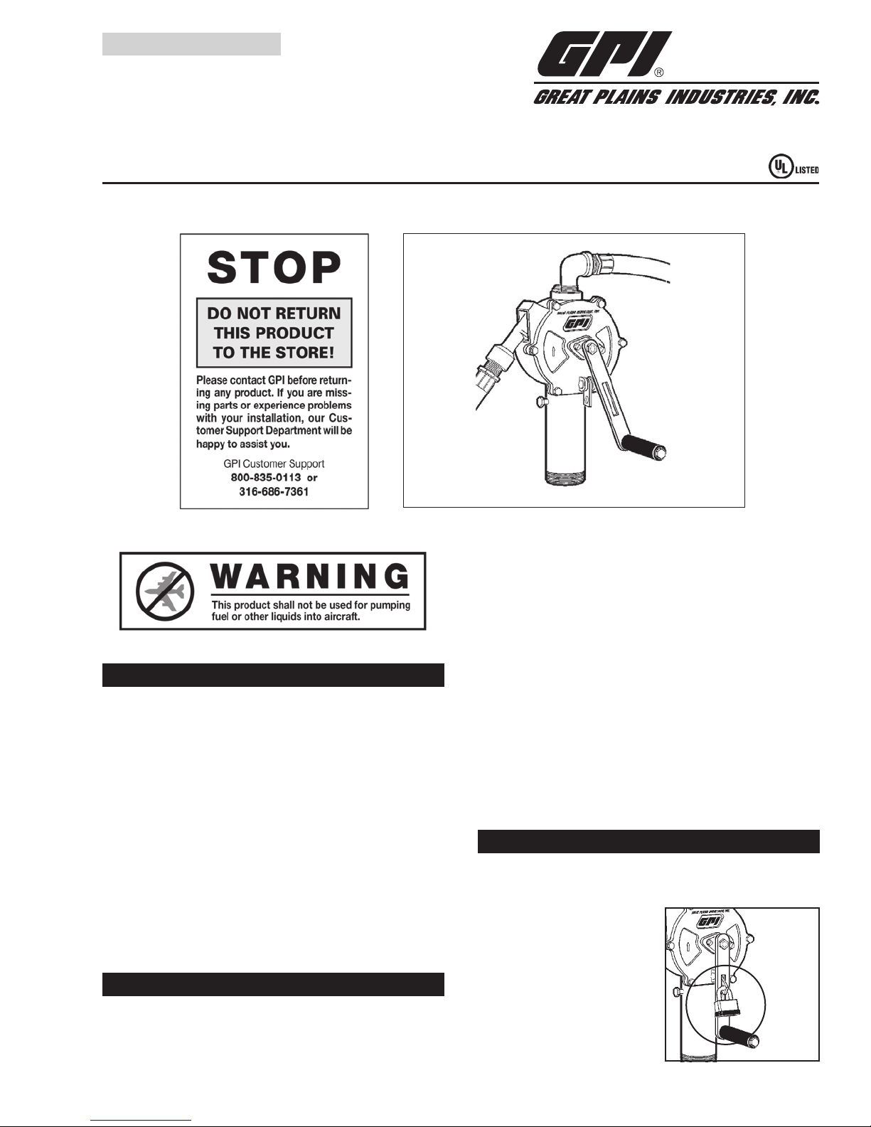
Use
standard
padlock
to secure
handle.

SPECIFICATIONS
PARTS AND SERVICE
The Rotary Hand Pump is compatible with gasoline (up to 15%
alcohol blends such as E15), diesel fuel (up to 20% biodiesel blends
such as B20), kerosene and up to medium weight oils.
Construction: L
ightweight, die-cast aluminum housing.
Stainless steel shaft. Fluorocarbon
seals. Cast iron rotor and carbon vanes.
Built-in anti-siphon vent.
Pumping Capacity: U
p to 10 gallons (38 litres) per 100
revolutions
Inlet: 1
Outlet: 3
Shipping Weight: 1
Hose and Nozzle: 3
-inch NPT female
/4-inch NPT female
7 lbs. (7.7 kg)
/4-inch x 8 foot (2.4m) Buna-N
statically grounded hose.
Aluminum Alloy unleaded nozzle
Suction Pipe: P
lastic, adjustable from 22 to 40 inches
(55 to 102cm)
For warranty consideration, parts or other service information,
please contact your local distributor or the GPI Customer Service
Department, during normal business hours at:
1-800-835-0113
To obtain prompt, efficient service, be prepared with:
he model number of your pump
• t
• the serial number or manufacturing date code of your pump,
and
• p
arts descriptions and numbers
Reference the Illustrated Parts List for specifics on parts. For warranty service, be prepared with your original sales slip or other
evidence of purchase date.
CAUTION
Do not return the pump without specific authority from the
GPI Customer Service Department. Due to strict regulations governing transportation, handling, and disposal
of hazardous or flammable liquids, GPI will not accept
pumps for rework unless they are completely free of
liquid residue.
TROUBLESHOOTING
SYMPTOM PROBABLE CAUSE CORRECTIVE ACTION
A. FLUID LEAKS AROUND 1. Retainer loose Tighten retainer screws.
SHAFT
if necessary.
B. FLUID LEAKS AT ANTI- 1. Anti-siphon vent or Remove vent cap. Loosen vent by turning counterclockwise. Remove
SIPHON VENT O-ring damaged vent and O-ring. Clean. To replace, seat O-ring on vent and screw vent
into place until bottomed out. Replace vent cap.
C. LOW FLOWRATE 1. Internal parts worn or Remove coverplate and inspect for wear on vanes, coverplate, and all
debris in vane cavity inside housing surfaces. Replace any scored parts.
2. Vanes cracked Remove coverplate and inspect for chips or cracks on vanes. If
necessary, replace vanes.
D. PUMP FAILS TO PUMP 1. Suction pipe leak Remove pump from tank and riser. Inspect the spacer and suction pipe
for wear or damage. Replace, as necessary, and install pump on tank.
2. Internal parts worn or Remove coverplate and inspect for wear on vanes, coverplate, and all
debris in vane cavity inside housing surfaces. Replace any scored parts.
3. Vanes cracked Remove coverplate and inspect for chips or cracks on vanes. If
necessary, install Overhaul Kit or replace vanes.
E. HANDLE TURNS HARD 1. Debris in vane cavity Remove pump from tank. Remove coverplate and inspect for debris in
OR PUMP SEIZED cavity. Clean cavity, vanes, and rotor. Flush contamination from tank.
Assemble and install pump.
2. Internal parts worn Remove pump from tank. Remove coverplate and inspect for damaged
necessary, install Overhaul Kit or replace vanes.
F. VANES STICKING 1. Debris in vane cavity Remove coverplate. Use emery cloth to remove debris or corrosion in
vane slots. Apply lubricant (WD-40
2.
O-ring worn Check shaft O-ring for excessive wear. Replace Shaft Seal O-ring,
®
) if needed.
 Loading...