

GPI QME10, QMF05, QME05, QMF10, QME20 Owner's Manual
...
SAVE THESE INSTRUCTIONS
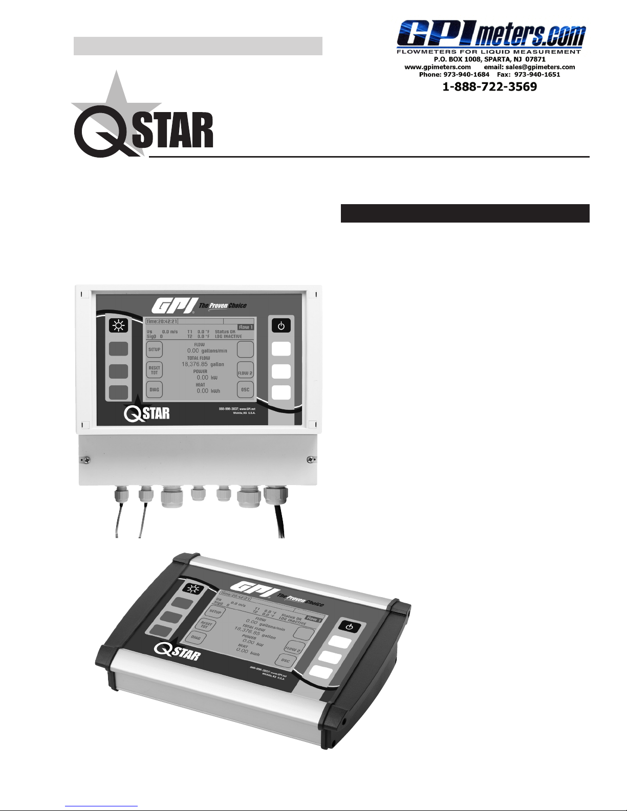
Fixed and Portable
Ultrasonic Flowmeter (UFM)
Owner’s Manual
TABLE OF CONTENTS
Key Aspects of QStar UFM..........................................3
Fixed
Approvals/CE...............................................................3
Measuring Principle ..................................................... 3
QStar Fixed UFM and Components ............................ 4
QStar Portable UFM and Components........................ 8
Operating ................................................................... 10
Getting Started .......................................................... 10
Preparing for Measurement ....................................... 13
Measuring with UFM.................................................. 15
Setup Parameters......................................................15
Measuring Windows .................................................. 31
Calibration ................................................................. 44
System Settings.........................................................44
Troubleshooting ......................................................... 46
Software Update ........................................................ 53
Fluid Properties ......................................................... 54
Specications ............................................................ 56
Portable
920222-0105/13
QSTAR FIXED AND PORTABLE UFM OWNER’S MANUAL
Text identied with an exclamation mark contains important information that relates to the basic data
and operation of the device.
Text identied with the letter “i” contain supplementary and helpful information.
i
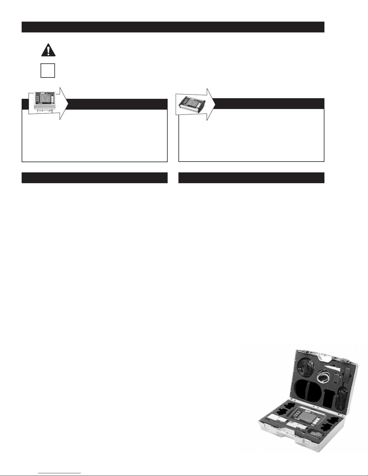
FIXED UFM
Text contained within this box applies specically
to the QStar FIXED UFM. If you have a PORTABLE
UFM, skip this section and go to the text with no
border, or the text in the PORTABLE UFM box.
FIXED UFM
PACKAGE INCLUDES:
• Transmitter
• Ultrasonic transducers
• Spacer bar for the ultrasonic transducers
(for types F10/F21)
• Stainless steel mounting belts
• Getting Started (“Quick-start”) manual
• USB drive with Owner’s Manual
• Ultrasonic coupling grease
Other ultrasonic transducers for smaller or larger pipe
dimensions, as well as clamp-on temperature sensors, are available on separate order. Contact GPI at
www.GPImeters.net or toll-free (888) 996-3837.
PORTABLE UFM
Text contained within this box applies specically
to the QStar PORTABLE UFM. For a FIXED
UFM, skip this section and go to the text with
no border, or the text in the FIXED UFM box.
PORTABLE UFM
PACKAGE INCLUDES:
• Hard-shell case
• QStar Portable ow transmitter
• Plug-in power adapter, plus IEC appliance power
cable
• Transducer cables
• Ultrasonic transducers
• Spacer bar for the ultrasonic transducers
• Cable for the 4 mA to 20 mA analog output (Mini
DIN, alligator clips)
• Digital output cable for the relay/pulse output
(Mini DIN, alligator clips)
2
TEL: 888-722-3569 • 973-940-1684 • FAX: 1-973-940-1651 • www.GPImeters.com
• USB cable
• Stainless steel mounting chains (up to 16 in.)
• Getting Started (“Quick-start”) manual
• USB drive with operating instructions
• Ultrasonic coupling grease
• Measuring tape
Other ultrasonic transducers for smaller
or larger pipe dimensions and clamp-on
temperature sensors, are available
on separate order. Contact GPI
at www.GPImeters.net or
toll-free (888) 996-3837.
KEY ASPECTS OF QSTAR UFM:
APPROVALS/CE
• Fixed or Portable system for measuring liquids in lled
piping systems.
• Uses the ultrasonic transit-time differential method.
• Heat measurement is included as standard application.
Clamp-on Fixed and Portable temperature sensors
are optional.
• Portable UFM can be operated in battery-powered
mode and on a power adapter for operation with 100%
duty cycle. Fixed UFM can be operated on a power
adapter.
• Supports measurements on piping with diameters
from 1/2" to 240" (depending on the sensor used).
• The uid to measure may have a temperature range
from -40° F to +300° F (depending on the transducer
used).
• You can save the measuring data to the internal
SD card, read the data via USB port and export this
data using Microsoft® ofce software such as Excel
(Portable UFM only).
• The device is equipped with an electrically isolated
relay output and two 4mA to 20mA current outputs
that can be operated in active and passive mode.
QStar UFM is compliant with the following
European Directives and Standards
Test Specications
DIN EN 55011 B (11/2007)
DIN EN 61000-4-2 (09/2008)
DIN EN 61000-4-3 (06/2008)
DIN EN 61000-4-4 (07/2005)
DIN EN 61000-4-5 (06/2007)
DIN EN 61000-4-6 (10/2008)
DIN EN 61000-4-8 (12/2001)
DIN EN 61000-4-11 (02/2005)
Test Requirements
DIN EN 61000-6-1 (10/2007)
DIN EN 61000-6-3 (09/2007)
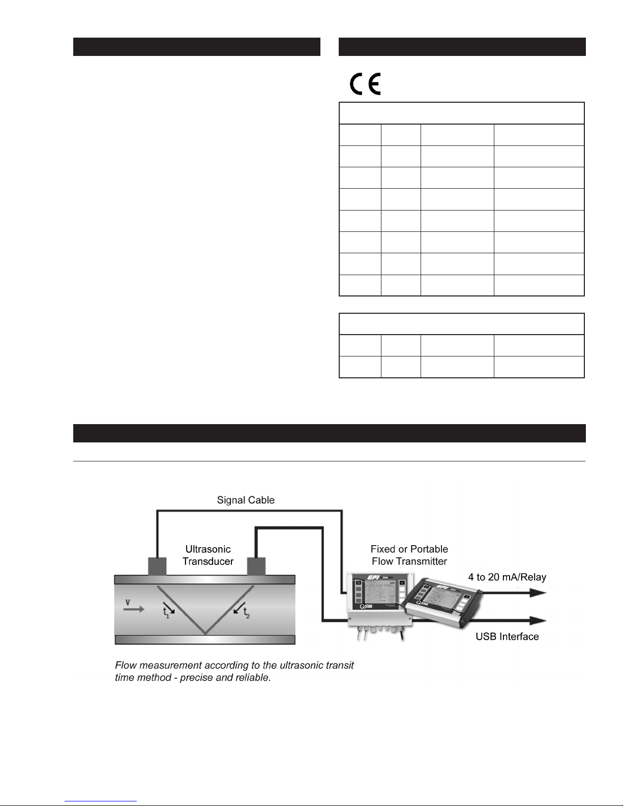
FIGURE 1: Measuring Principle
ULTRASONIC MEASURING PRINCIPAL
TEL: 888-722-3569 • 973-940-1684 • FAX: 1-973-940-1651 • www.GPImeters.com
3
The UFM employs precise, ultrasonic transit-time dif-
cos221
)12(
−
TT
TT
π
4cos221
TT
ferential method. This method involves installation of
two ultrasonic transducers on the surface of the piping
and their interconnection with the electronic evaluation
system. The ultrasonic transducers operate in alternating
mode as transmitter and receiver with cyclic exchange of
ultrasonic signals. Measurements cover the transit times
of the upstream and downstream signals (t1, t2). The UFM
measures the transit-time differential of the ultrasonic
signals t1 and t2 that travel upstream and downstream.
These signals are accelerated (t1) or retarded (t2). The
difference that develops between both signal transit times
is proportional to ow velocity and is used in combination
with the piping geometry data for precise calculation of
the volumetric owrate.
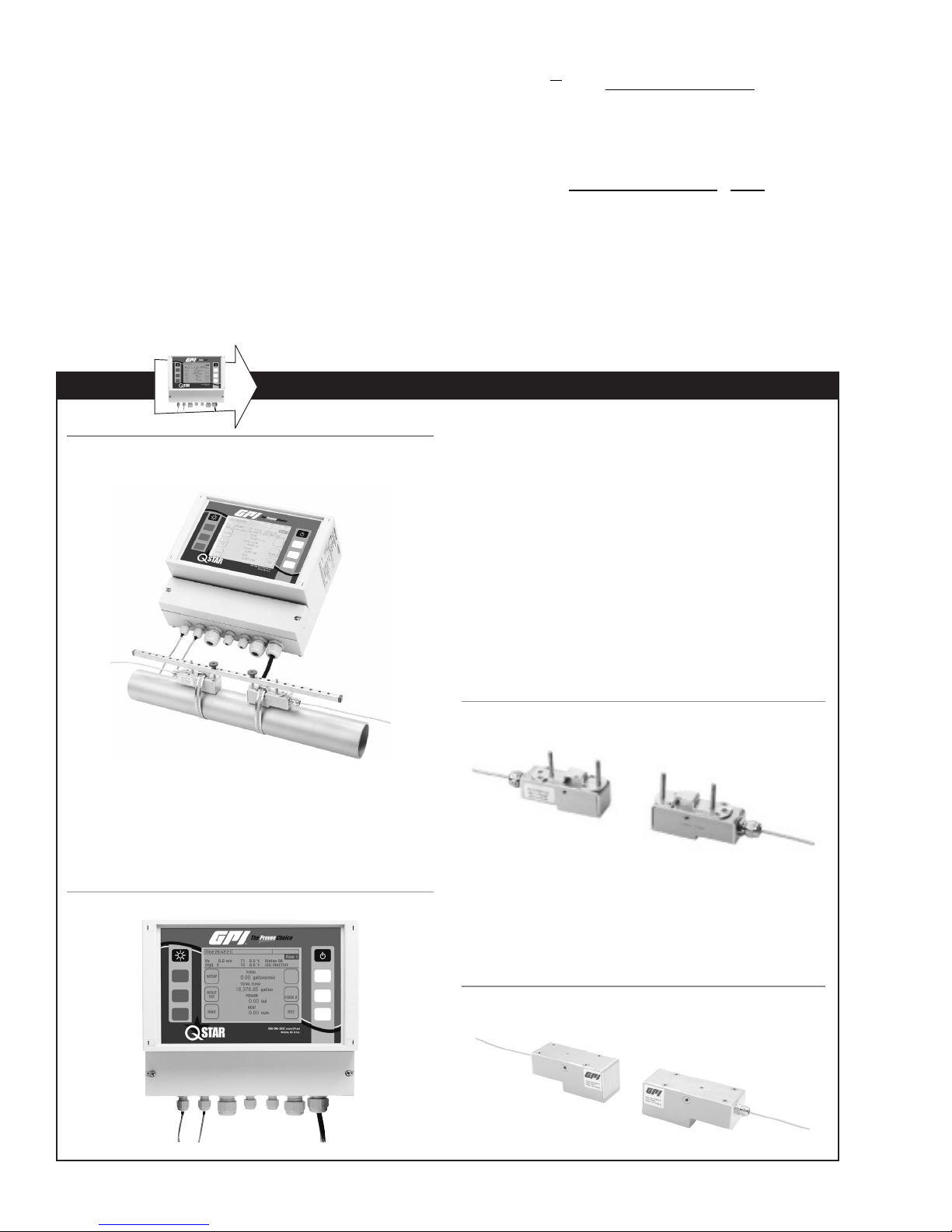
FIXED UFM AND COMPONENTS
=
Lv
α
α
D
2
⋅⋅
⋅⋅
Calculation of ow velocity [m/s]
)12(
TT
−
LQ
=
⋅⋅
Calculation of owrate [m3/s]
The ow transmitter uses a sophisticated cross-correlation
to detect signals. This ensures a reliable detection of
signals even in case of harsh circumstances like gas
and/or particle load.
FIGURE 2: UFM – with Mounted Ultrasonic Transducers (Bottom)
and Flow Transmitters
The UFM consists of the ultrasonic transducers and the
ow transmitter that are mounted onto piping.
FLOW TRANSMITTER
The ow transmitter processes the signals and makes
the measurement results available to the user.
ULTRASONIC TRANSDUCERS
The ultrasonic transducers are mounted onto the piping and transmit and receive the ultrasonic signals
that are used in the ow transmitter to calculate the
volumetric owrate.
Ultrasonic transducers:
QMF-F10 (1 MHz) for pipe diameters 1.25" to 16"
QMF-F21 (2 MHz) for pipe diameters 3/8" to 4"
Operating temperatures: -40° F to 300° F
FIGURE 4: Ultrasonic Transducers (F10/F21) typically
used with Spacer Bar (not shown)
FIGURE 3: Flow Transmitter
4
TEL: 888-722-3569 • 973-940-1684 • FAX: 1-973-940-1651 • www.GPImeters.com
Ultrasonic transducer:
QMF-F05 (0.5 MHz) for pipe diameters 8" to 240"
Operating temperatures: -40° F to 180° F
(300° F optional on request)
FIGURE 5: Ultrasonic Transducers (Type F05)
FIXED UFM AND COMPONENTS (Continued)
MOUNTING MATERIAL AND
ACCESSORIES
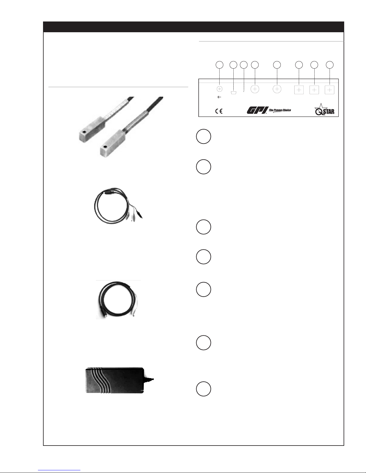
Signal cables
Signal cables are a part of the ultrasonic transducers
and cannot be separated from transducers.
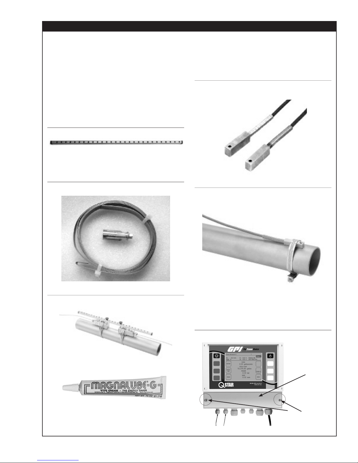
Spacer bar for transducer mounting
For transducers F10 and F21 (Transducer QMF-F05
is mounted on pipes using textile tape rather than
spacer bar).
FIGURE 6: Spacer bar
Metal Mounting Belt for Transducer
Mounting
FIGURE 7: Mounting Belt (Stainless Steel)
QMF-PT100 Temperature sensors
The clamp-on temperature sensors collect temperature data in heating and cooling circuits.
This data is then used to calculate heating and cooling
quantities.
FIGURE 9: Clamp-on temperature sensors, QMF-PT100
(optional)
FIGURE 10: QMF-PT100 (optional) Temperature Sensor
Mounted with Metal Belt
FIGURE 8: Transducers Mounted with Spacer Bar and
Mounting Belts
Coupling grease
Apply the ultrasonic coupling gel between the ultra-
sonic transducer and the piping in order to optimize
signal input.
TEL: 888-722-3569 • 973-940-1684 • FAX: 1-973-940-1651 • www.GPImeters.com
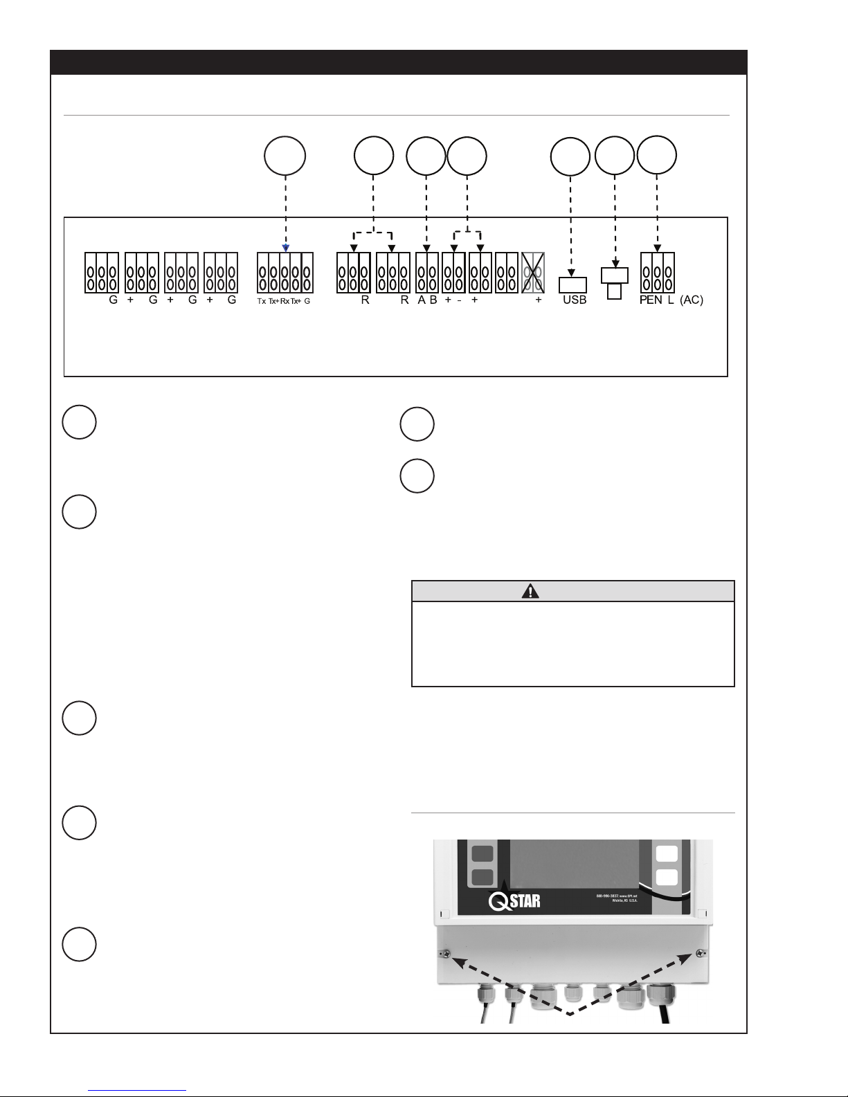
Interfaces of UFM
Open the cover to access the connecting terminals.
FIGURE 11: Front view of transmitter showing cover
Cover
Remove
Screws
5
FIXED UFM AND COMPONENTS (Continued)
CONNECTOR BOARD
FIGURE 12: Connecting Terminals
1 2 3 4 5 6 7
+ - - - - - + --
UP1 DN1 UP2 DN2 RS232/ 485
1 RS232/RS485 Interface boards
Digital Interface boards RS232 or RS485 are
available as an option to provide digital communication via ASCI strings.
2 Input for temperature sensors
QMF-PT100 (3-wire)
The two temperature sensors (feed and return
pipe) can be connected in order to measure
heat/thermal output. The ow transmitter always
includes the capability for heat/thermal output
measurement. Note that (if required by customer)
the QMF-PT100 inputs can also be used to reset
the counters. If you use this reset function you
cannot measure heat/thermal output at same
time.
WW WW
QMF-
QMF-
PT100
PT100
Relay OUT2 OUT1 DO1 DO2 Reset Power
6 Hardware Reset
Used to reset unit (for hang-ups).
7 Power Supply
Location for connecting the supply voltage. QStar
UFM is available as AC (90-240VAC) and DC
(18-36VDC) version.
Always use the correct voltage for the UFM.
Improper supply voltage might seriously
damage the ow transmitter. Check the type
of power supply on the name plate (printed
on right side of enclosure of ow transmitter.
CAUTION
+ - (DC)
3 Relay output (potential-free)
This output is potential-free NO (normally open)
relay output. Use this output to establish an
alarm (for example, when exceeding a certain
ow speed).
4 Analog output 4-20mA (active)
The 4-20mA outputs can be used to submit
measurement data like ow, thermal output and
velocity to the Programmable Logic Controller
(PLC). These outputs are in active mode (supply
voltage provided internally by ow transmitter).
5 USB- Interface
Used for rmware updates. Standard USB (micro
USB)- cable required to connect to a PC.
6
Wiring
The connection terminals are located under the lower
cover. Remove the two screws and plastic cover to
gain access to the connection terminals.
FIGURE 13: Accessing the Connection Terminals
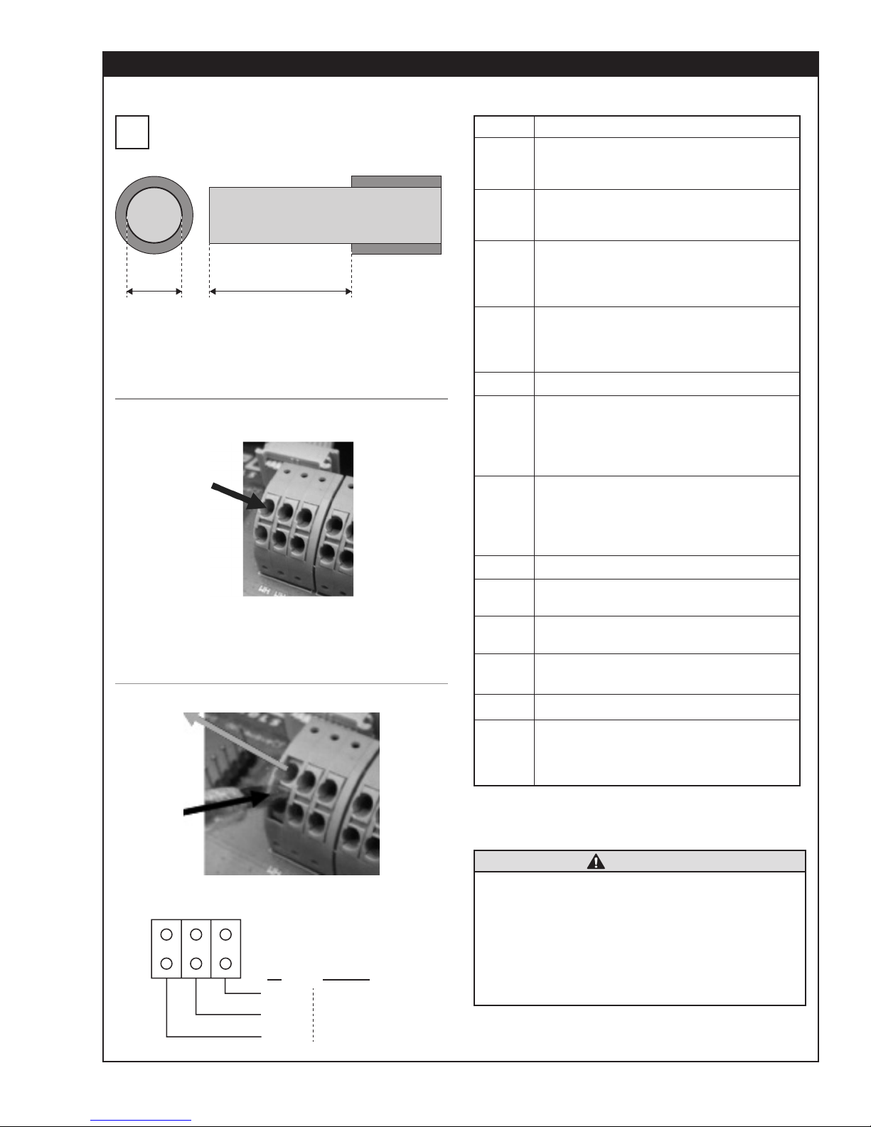
FIXED UFM AND COMPONENTS (Continued)
.5".015" - .030"
AC TERMINAL BLOCK WIRING
Use cables with 16-26 AWG wires. Wires should
be stripped about .5 in. to allow proper contact
i
to terminals.
Put the stripped end of the related wire into the
related hole. Wires will be held by spring. It might
be helpful to use end sleeves or tin the wire ends.
FIGURE 14: Connection Terminals – Fasten Cables
Use a slotted screwdriver to unfasten wires, then press
middle part between the two holes as shown to loosen
the spring and remove the wires.
FIGURE 15: Connection Terminals - Unfasten Wires
Terminal Diagram
Terminals
UP1
DN1
UP2
DN2
RS485 Optional Interface board
QMF-
PT100
QMF-
PT100
Relay Relay output, external voltage required
OUT1
OUT2
DO1
DO2 Optional, Digital output 2
Designation
Connection of upstream transducer
Red wire to be connected to +
Black wire to be connected to -
Connection of downstream transducer
Red wire to be connected to +
Black wire to be connected to -
Connection of upstream transducer
(path2)
Red wire to be connected to +
Black wire to be connected to -
Connection of downstream transducer
(path2)
Red wire to be connected to +
Black wire to be connected to -
Connect temperature sensors
(measuring colder temperature) to left
QMF-PT100 terminal
WH = White wire from QMF-PT100
RD = Red wire from QMF-PT100
Connect temperature sensors
(measuring warmer temperature) to
right QMF-PT100 terminal
WH = White wire from QMF-PT100
RD = Red wire from QMF-PT100
Analog output1, 4…20mA, active, voltage provided internally
Analog output2, 4…20mA, active, voltage provided internally
Digital output (Transistor), passive
mode, external voltage required.
PE NL1
US EUROPE
BLACK
WHITE
GREEN
BROWN
BLUE
GREEN/YELLOW
Power
Supply
Either DC (18-36VDC) or AC (90-
240VAC). Check order conrmation
or name plate on ow transmitter for
operating voltage.
CAUTION
• The 4-20mA outputs are set in active mode.
That means the required voltage is provided
by ow transmitter internally. DO NOT USE
additional external voltage.
• The digital output is set in passive mode and
requires external voltage to be operated.
• Relay is rated to max. 45V, 0.25mA. These
values must not be exceeded.
7
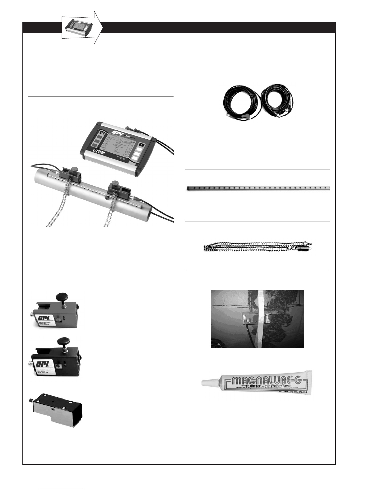
PORTABLE UFM AND COMPONENTS
PORTABLE FLOW TRANSMITTER
Your UFM consists of the ultrasonic transducers and
the ow transmitter that are mounted onto your piping.
The ow transmitter processes the signals and provides
the measurement results.
FIGURE 16: PORTABLE Flow Transmitter (Top) and
Mounted Ultrasonic Transducers (Bottom)
MOUNTING MATERIAL AND
ACCESSORIES
Signal cables
Spacer bar for transducer mounting
For QMP-F10 and QMP-F21 (QMP-F05 is mounted
on pipes using textile tape rather than spacer bar).
FIGURE 17: Spacer bar
Chains for Transducer Mounting
FIGURE 18: Mounting Chain (Stainless Steel)
ULTRASONIC TRANSDUCERS
The ultrasonic transducers mount onto the piping to
transmit and receive the ultrasonic signals used in the
ow transmitter to calculate the volumetric owrate.
Ultrasonic transducer QMP-F21
(2 MHz), RED housing, for pipe
diameters from 0.5 to 4.0 inches.
Operating temperatures: -40° F to
300° F
Ultrasonic transducer QMP-F10
(1 MHz), BLUE housing. Pipe diameters: 1.5 to 16 inches. Operating
temperatures: -40° F to 300° F
Ultrasonic transducer QMP-F05
(0.5 MHz), GREEN housing. For
pipe diameters from 8 to 240
inches. Operating temperatures:
-40° F to 176° F (300° F optional
on request)
FIGURE 19: Transducer QMP-F05 (500 kHZ) for large
pipes – Mounting with textile tape.
Coupling grease
Apply the ultrasonic coupling gel between the ultrasonic
transducer and the piping to optimize signal input.
8
PORTABLE UFM AND COMPONENTS (Continued)
78
QMP-PT100 Temperature sensors
(Optional)
The clamp-on temperature sensors collect temperature data in heating and cooling circuits.
Use this data to calculate heating and cooling quantities.
FIGURE 20: QMP-PT100 clamp-on temperature sensors
4-20mA analog output cable
FIGURE 21: Back view of Portable UFM connections
1234 56
Reset Down Up Relays/ T1/T2Analog OutUSBPower
Impulse OUT
1 Power Input
This jack is used to connect the plug-in power
adapter that is included with the UFM package.
2 USB Interface (Mini.USB Type B)
Enables access to the integrated SD memory
card from a PC. This card is used to store data
logging information and measurement data (LOG
les). Windows XP or later versions detect the
internal SD Card as mass storage medium. No
need to install additional drivers.
QMP-001
The analog output cables can be used to connect an
external data logger or recorder to the ow transmitter for the transmission of measured values such as
owrates, or thermal output.
Cable for Relay/Pulse
The relay connecting cable can be used to trigger
alerts. For example, when exceeding a certain owrate.
Power adapter 100-240V, 47-63Hz, 1A
The power adapter is normally used to charge the
battery. Your UFM supports permanent operation by
using the power adapter.
3 Hardware Reset
Use a small screwdriver (or paper clip) to
press the reset button.
4/5 BNC Inputs for Ultrasonic
Transducers
Jacks for the ultrasonic transducers.
6 Relay/Pulse Output (4-Pol Mini DIN)
Electrically isolated output with NO (normally
open) contact. This internal NO contact is open
unless an actuating signal is generated. Allows
user to assign alarm or threshold limit functions
to this output.
7 Input for Temperature Sensors
QMP-PT100 (6-Pole Mini DIN)
Receptacle for the optional temperature sen-
sors that enable the use of the internal heat
measurement function of the UFM.
8 4-20mA Analog Output
(5-Pol Mini DIN)
These outputs can be assigned variables such
as the owrate and return a current that is
proportional to the value of the variables. The
outputs operate in active (power provided by
ow transmitter) 2-wire mode.
9
SAFETY INSTRUCTIONS
HOW TO NAVIGATE
• The ow transmitter cannot be operated outside the
temperature range from -4° F to 140° F.
• The ultrasonic transducers are sensitive to mechanical
stress such as impact and vibration. Always safeguard
the transducers against strong vibration or impact to
avoid damage or destruction.
• The plug-in power supply is suitable for in-door use
only.
• The plug-in power adapter or the power cable must
be replaced completely in the case of mechanical or
electrical damage.
• The ow transmitter is not approved for operation in
hazardous locations. The standard ultrasonic transducers are not approved for operation in hazardous
locations.
• The ultrasonic transducers may not be operated
outside their specied uid temperatures.
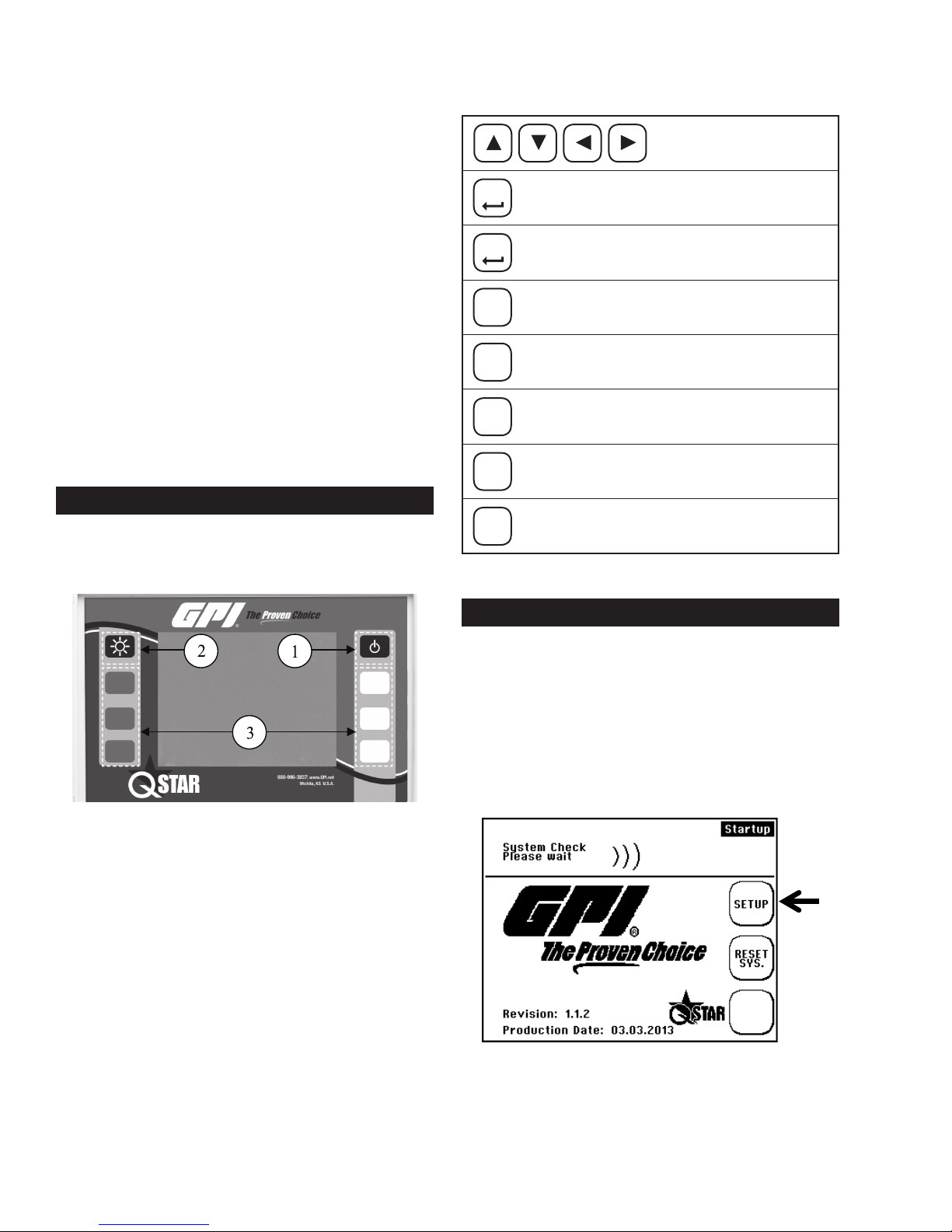
OPERATING
Use the corresponding multifunctional buttons:
Arrow buttons for
navigation
ENTER
NEXT
BACK
XYZ
Conrms entry
Conrms entries and opens the next window
Returns to the previous window
Increases the value
+
–
Reduces the value
Activates a certain function (depending on
chosen menu)
No function
CONTROL BUTTONS
1. Turns on Portable transmitter. Fixed transmitter will
automatically start when connected to voltage supply.
2. Switches the backlight On and Off.
3. Multifunctional buttons: Use this button to select the
function that is displayed next to it on the screen.
GETTING STARTED
BASIC SETTINGS, MAIN MENU,
NAVIGATION
Setting Language
1. Switch on the device. During the start sequence, press
the multifunctional button that is located next to the
“SETUP” eld.
10

2. Conrm the “SETUP LANG.” button
2. Select “COMPL Setup” when window appears.
3. Use the arrows in the next window to select the dialog
language. Conrm entry with “Enter”. Exit the menu
with “SETUP.”
CAUTION
The language setting selects the language used
in the menus. The language in the elds next to
the multifunctional button remains unchanged.
Navigation in Main Menu “Flow 1”
The “Flow 1” measuring window is automatically opened
with a delay of a few seconds after turning on the power.
The “Flow 1” measuring window provides an overview
of all data that is necessary for ow and optional heat
measurements.
You are now in the main menu. Select all necessary
functions of the device in this menu.
To return to the measuring window, proceed as follows:
Select “ESC” -> “MEAS” in the next window.
To accelerate access to the main menu after
power on, select the start sequence “SETUP.”
i
Select “COMPL SETUP” in the next window.
Setting the Time and Date
After selecting the dialog language, the setup menu opens.
1. Scroll the “System Setup” menu command using the
arrow keys.
1. Select “Setup”
11
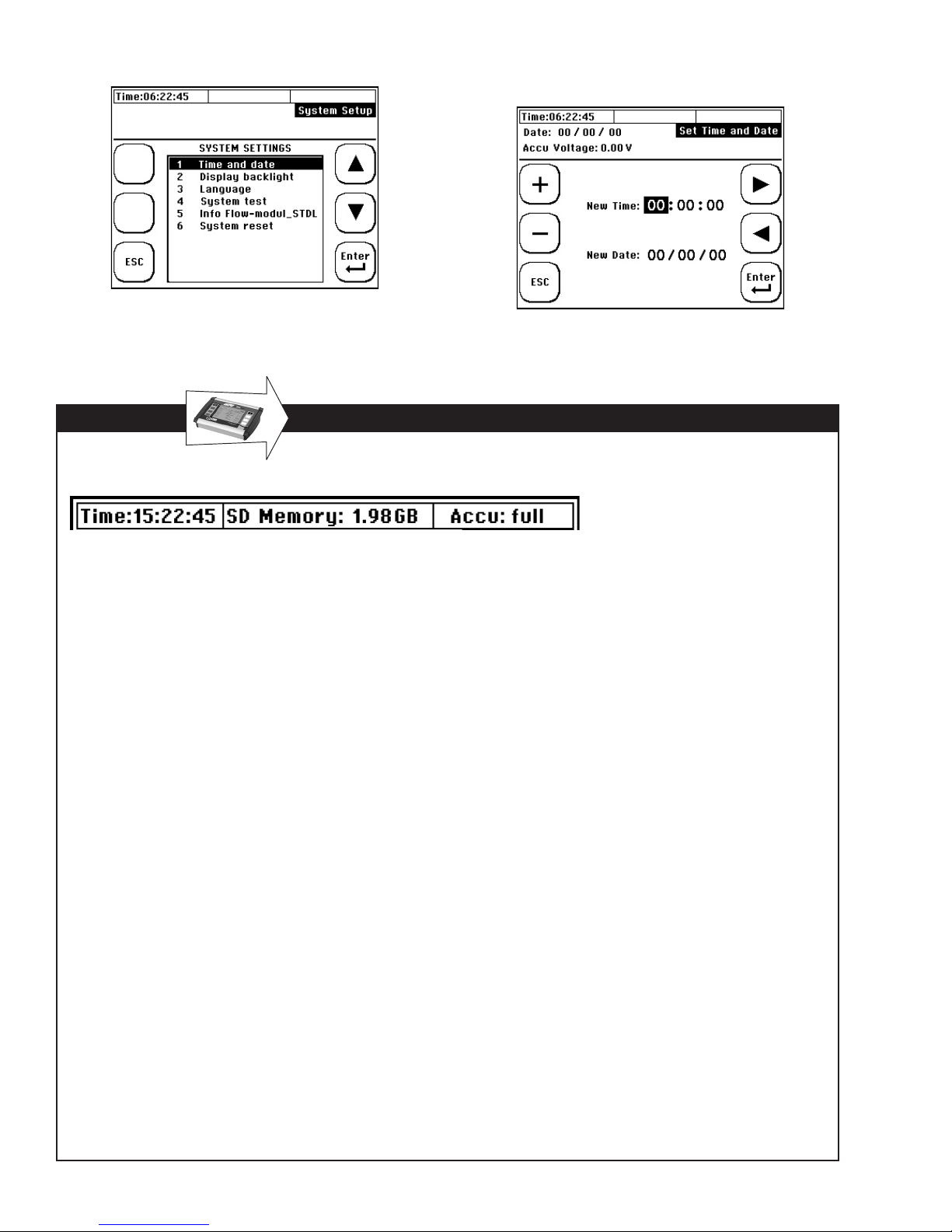
2. Select the “Time and Date” menu command
APPLIES TO PORTABLE QSTAR
The status bar is located in the uppermost row of the display.
3. Enter the time as: Hour (hh): Minute (mm): Second (ss).
Enter the date as: Month (mm): Day (dd): Year (yy).
Time
Displays the current time (system time). The time stamp
that is derived from the system time will be applied to
the measurement data.
SD memory
Displays the free space on the internal SD memory
card of the device (standard is 2 GB).
Backup battery
Provides information about the status of the rechargeable battery.
• Load: The device is powered using the power
adapter while the battery is charged. The empty
battery needs a charging time of approximately ve
hours.
• Full: The battery is in a charged state. The device
may be operated for approximately ve hours when
the display backlight is switched off or for approxi-
mately three hours when it is switched on.
Percentage display
Displays the charging state of the battery.
The times specied applies to a new battery. The factual
operating/load cycles may deviate from the specied
time values.
12
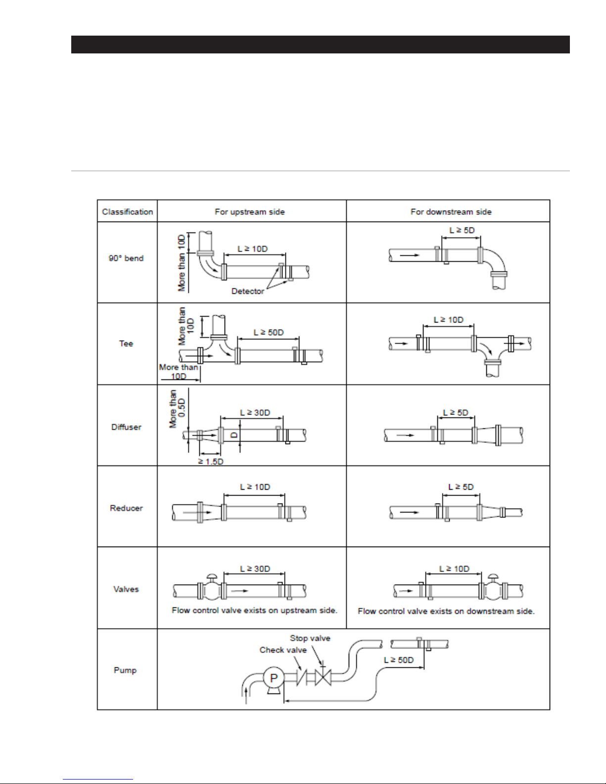
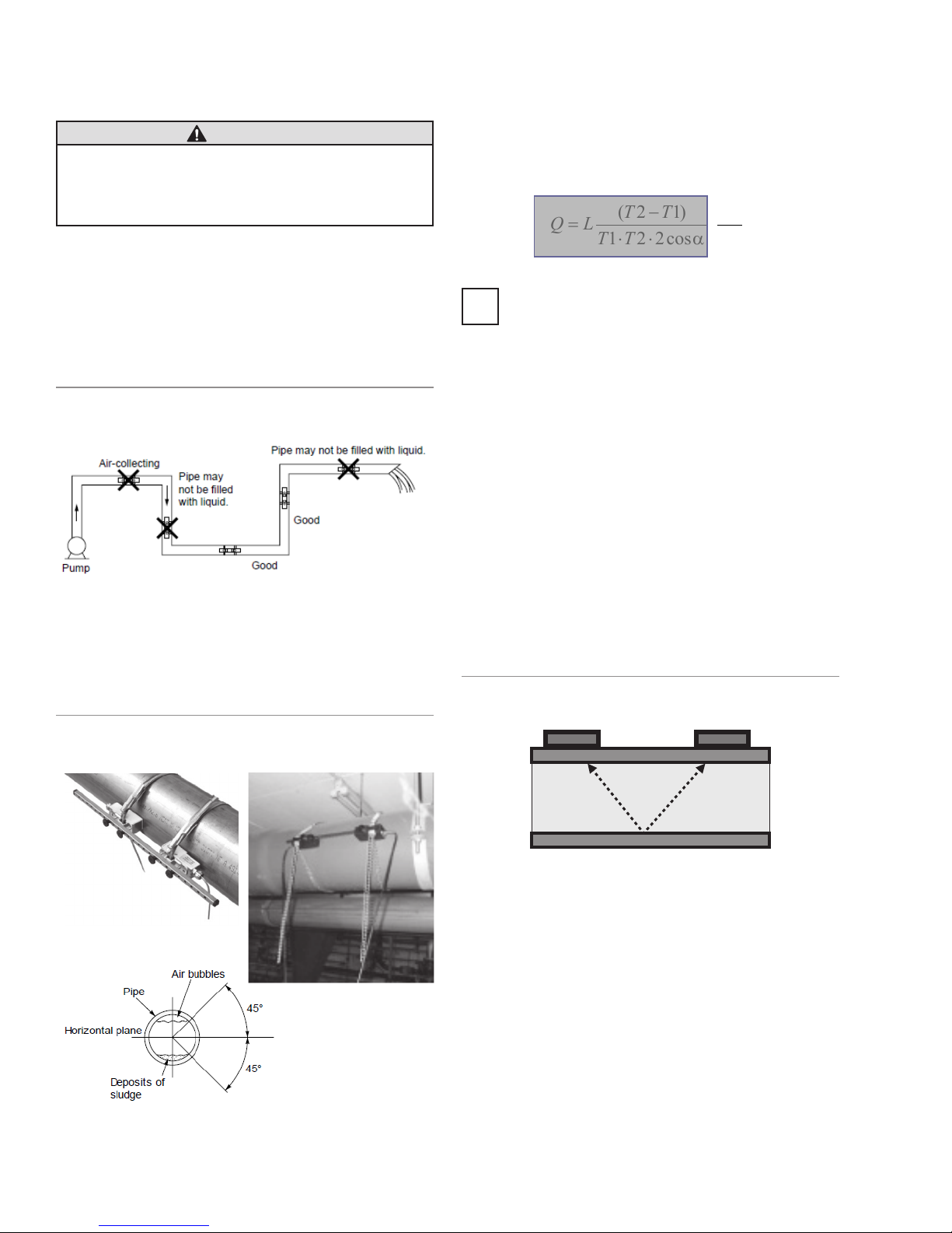
PREPARING FOR MEASUREMENT
The following section elaborates on essential aspects that must be taken into account for successful
owrate measurements.
STRAIGHT RUN REQUIREMENTS
The selection of the mounting location has a signicant impact on measurement quality. The
charge and discharge areas listed in the following table should be taken into account.
FIGURE 22: Straight run requirements
13
TRANSDUCER MOUNTING POSITIONS
4cos221
TT
Mounting Ultrasonic Transducers
CAUTION
The pipe must always be lled completely
at the mounting positions of the ultrasonic
transducers. It is not possible to take
measurements on partially lled pipe.
The ultrasonic transducer can be operated in any mount-
ing position. However, conforming with the mounting
positions shown below is mandatory. The drawing shows
the side view of the piping.
Mounting Ultrasonic Transducers On
Horizontal Pipe
FIGURE 23: Preferable mounting positions for ultrasonic
transducers (1)
UFM uses the cross section of the pipe to calculate
the ow. The cross section is calculated from the inner
diameter setup (user setting). If there is sedimentation
in the pipe, which decreases the real inner diameter, a
small amount of uncertainty may result. The same hap-
pens when the inner diameter is not known/estimated.
D
2
πα⋅⋅
)12(
TT
LQ
=
−
⋅⋅
To measure pipes with unknown wall thicknesses
a wall thickness gauge is avaiable from GPI. Ask
i
GPI Customer Service Representative for more
information or visit www.GPImeters.net.
Ultrasonic Transducers On Non-Planar
Surface
Never mount the transducers on non-planar surfaces such
as welding seams or deformations. Always try to remove
thick and uneven protective paint coating from the piping
area where the ultrasonic transducers will be mounted.
On horizontal piping, mount the transducer with an offset
of about +/-45% to the horizontal plane. Otherwise, there
is a risk of the accumulation of bubbles in the upper sec-
tion and sedimentation in the lower section of the pipe.
FIGURE 24: Preferred mounting positions for ultrasonic
transducers (2)
Mounting Ultrasonic Transducers
Following are the options for mounting the ultrasonic transducers. The V-mode is standard for most applications.
V-Mode
FIGURE 25: Mounting of transducers in V-mode
Transducer 1 Transducer 2
In the V-mode, both ultrasonic transducers are mounted
onto the same side of the pipe. This mode is the standard
for small and medium pipe dimensions. The ultrasonic
signals are reected from the pipe wall.
14
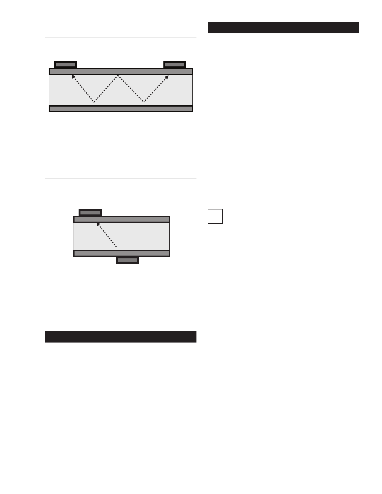
W-Mode
Transducer 1
SETUP PARAMETERS
FIGURE 26: Mounting of Transducers in W-Mode
Transducer 1 Transducer 2
The W-mode is a special method for mounting the ultrasonic transducers. This method is usually employed on
very small pipes.
Z-Mode
FIGURE 27: Mounting of Transducers in Z-Mode
Transducer 2
The Z-mode is a special method for mounting the ultrasonic transducers. The signal is transmitted across
a shorter distance with this installation method. Use for
measuring large-scale piping systems, or where the sys-
tem is lled with heavily contaminated or gas-loaded uid.
Ths section denes the input of all data that is necessary
for ow measurement.
• “QUICK SETUP”: The Quick Setup guide offers stepby-step instructions on the essential tasks required to
setup parameters.
• “COMPL SETUP”: The complete setup function
enables access to all options and expert settings.
WHAT NEEDS TO BE SETUP
• The pipe’s outer diameter or circumference.
• The wall thickness of the pipe. The material and thick-
ness of the pipe lining, if such lining exists.
• The pipe material
• The uid
• The type of ultrasonic transducers
• The mounting mode for the ultrasonic transducers
Ultrasonic measurement is based on the signal
transit time process. The ultrasonic signals
i
penetrate the piping and the uid. In order to
calculate the signal transit time, each uid, pip-
ing material and existing lining will be assigned a
sonic speed value, as well as the pipe diameter
or circumference value. The tabular database
species the sonic speed values for the materials
and uid. The sonic speed for materials not listed
in the tables must be entered manually. Tables
that list additional sonic speed parameters for
different materials are available in the back of
these operating instructions.
MEASURING WITH UFM
5 Steps to Flow Measurement:
• Select a suitable location for mounting the ultrasonic
transducers
• Setup the UFM pipe parameters
• Mount the ultrasonic transducers onto the piping
• Perform a zero calibration
• Start the ow measurement
15
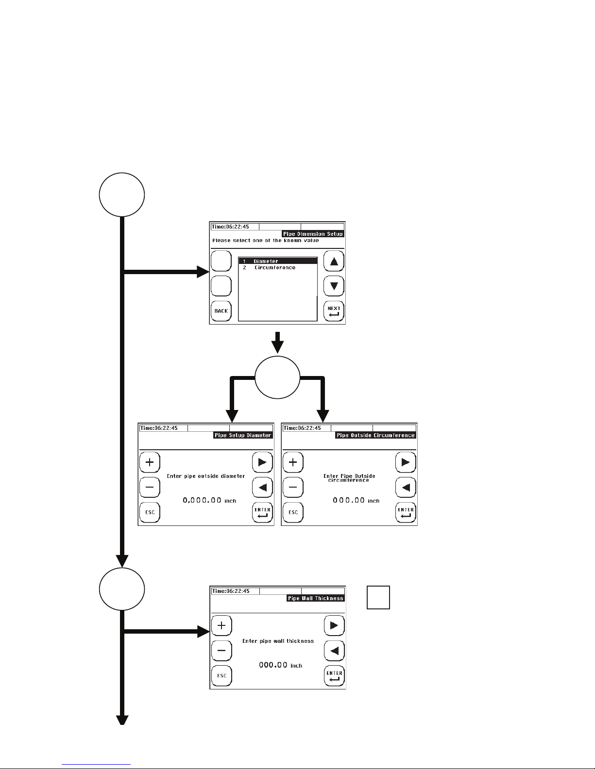
USING QUICK SETUP
START
Accessing the setup dialog:
After power on: Select “Setup” -> “Quick Setup” within the start sequence.
In the primary measuring window “Flow 1”: Select “Setup” -> “Quick “Setup.”
Enter the kinematic viscosity of the uid:
Specify whether to enter
the pipe circumference
or outer diameter.
1
2
Enter the outer diameter
OR
Enter the outside
circumference
i
Use a wall thickness
meter if wall thickness
is unknown, or
consult published
pipe standards.
16
Enter the pipe’s wall thickness
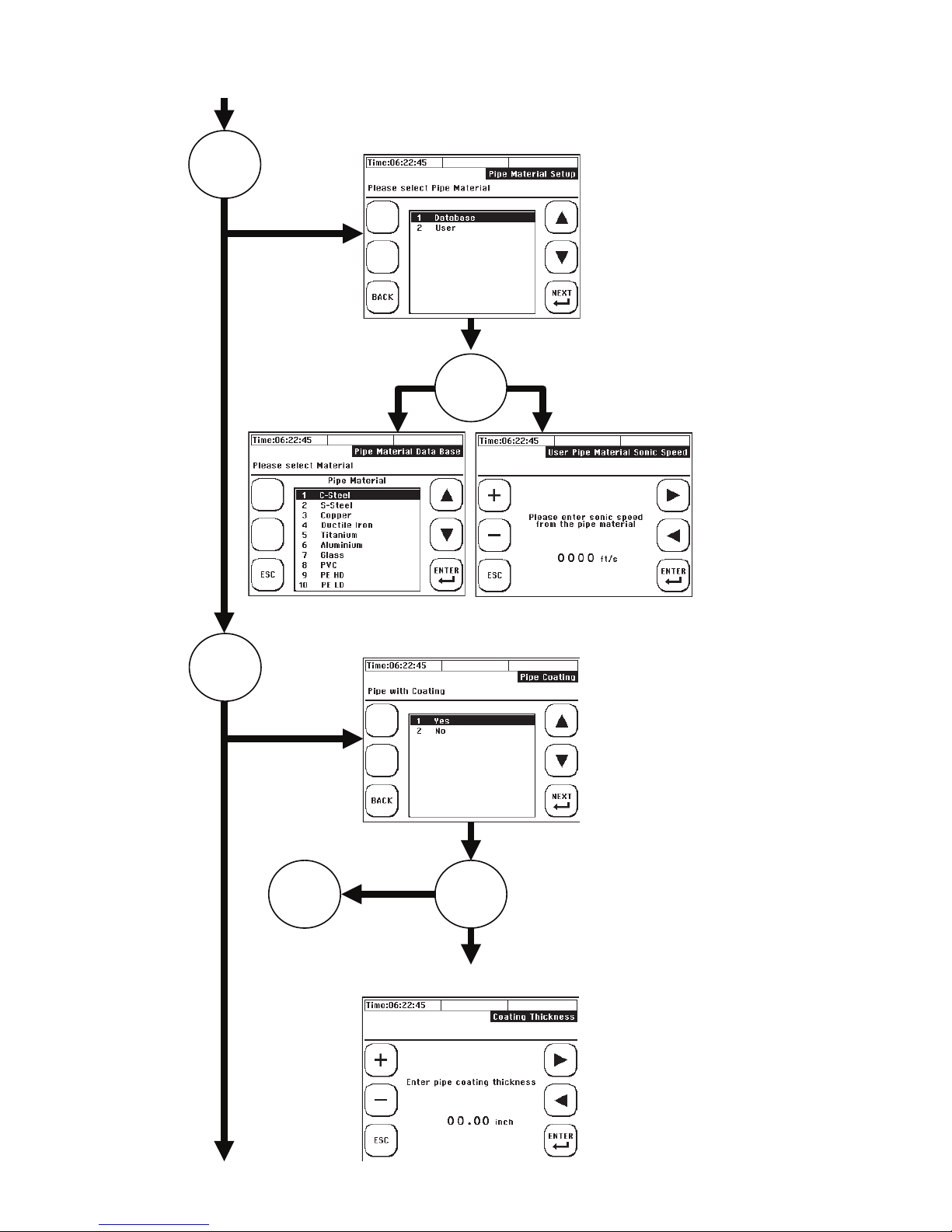
USING QUICK SETUP (CONTINUED)
Choose pipe material
3
OR
4
Does the pipe have a lining YES/NO?
NO
OR5
YES. Enter the thickness of the lining.
Select the database,
or user input if a
material is not listed
in the database.
17

USING QUICK SETUP (CONTINUED)
OR
Choose lining material from
the database.
5
Enter speed of sound of
user-dened coating.
Select the uid:
OR
18
Enter the kinematic
viscosity of the
medium:
 Loading...