

Page 1

SAVE THESE INSTRUCTIONS
Commercial Grade
Q9 COMPUTER
ELECTRONICS
Owner’s Manual
920787-01 Rev H 11/02/2020
Page 2

To the owner . .
Congratulations on receiving your
GPI Commercial Grade Computer
Electronics. We are pleased to pro‑
vide you with a product designed
to give you maximum reliability and
eciency.
Our business is the design, manu‑
facture, and marketing of liquid han‑
dling, agricultural, and recreational
products. We succeed because we
provide customers with innovative,
reliable, safe, timely, and compet‑
itively‑priced products. We pride
ourselves in conducting our business
with integrity and professionalism.
We are proud to provide you with a
quality product and the support you
need to obtain years of safe, depend‑
able service.
Victor Lukic, President
Great Plains Industries, Inc.
TABLE OF CONTENTS
General Information .............................2
Meter Installation .................................3
Troubleshooting ...................................4
Specications ......................................5
Installation ...........................................8
Operation .............................................9
Parts ..................................................17
Service...............................................17
GENERAL INFORMATION
This manual will assist you in oper‑
ating and maintaining the Computer
Electronics of the GPI Commer‑
cial Grade Meters. (See Figure 1)
Calibration details are given in this
manual. Information on turbine hous‑
ings and accessory modules are
contained in other manuals. Please
reference those as necessary.
TURBINE HOUSIN G
2
Figure 1
COMPUTER
ELECTRONICS
Before Getting Started
Take the time to fully acquaint your‑
self with all information about the
components of your GPI Electronic
Digital Meter. If you need assistance,
contact the distributor from whom
you purchased your computer.
This symbol is used through‑
out the manual to call your
attention to safety messages.
WARNING
CAUTION
Notes give information that can
improveeciency ofoperations.
Warnings alert
you to the poten‑
tial for personal
injury.
Cautions call
your attention to
practices or pro‑
cedures which
may damage your
equipment.
Page 3
It is your responsibility to make sure
that all operators have access to ad‑
equate instructions about safe oper‑
ating and maintenance procedures.
Read Me!
For your safety, review the major
warnings and cautions below before
operating your equipment.
WARNING
The apparatus enclosure may
contain aluminum and is consid‑
ered to constitute a potential risk
of ignition by impact or friction.
Care must be taken into account
during installation and use to
prevent impact or friction.
WARNING
Part of the enclosure is con‑
structed from plastic. To prevent
the risk of electrostatic sparking
the plastic surface should only
be cleaned with a damp cloth.
1. This equipment is approved to
handleonly uidsthatarecom‑
patible with all wetted materials.
2. When measuring ammable liq‑
uids, observe precautions against
reorexplosion.
3. When handling hazardous liq‑
uids, always follow the liquid
manufacturer’s safety precau‑
tions.
4. When working in hazardous
environments, always exercise
appropriate safety precautions.
5. For best results, always verify
accuracy before use.
METER INSTALLATION
Avoid electronically “noisy”
environments. Install at least 6
inches (15.2 cm) away from motors,
relays, or transformers.
All GPI A1 Series meters are Factory
Mutual Approved and carry a Class
1, Division 1 Approval for hazardous
environments. In addition, GPI meters
have NEMA Type 4 enclosures.
They are tested and calibrated at
the factory using state‑of‑the‑art
calibration procedures and testing
equipment.
To ensure accurate measurement,
remove all air from the system before
use.
1. Ensure some back pressure on
the turbine.
2. Open the discharge valve
or nozzle and allow fluid to
completelyllthesystem.Make
sure the stream is full and steady.
3. Close the discharge valve or
nozzle.
4. Start normal operations.
It is strongly recommended that
accuracy be veried prior to use.
To do this, remove all air from the
system, measure an exact known
volume into an accurate container,
and verify the volume against the
readout or recording equipment. If
necessary, use a correction factor
to figure final volume. For best
results,accuracyshouldbeveried
periodically as part of a routine
maintenance schedule.
3
Page 4

TROUBLESHOOTING
Symptom Probable Cause Corrective Action
A. METER IS NOT 1. Field Calibration not Field calibrate again or select
ACCURATE performed properly Factory Calibration.
2. Factory Calibration not Perform a Field Calibration accord‑
suitable for liquid being ing to Calibration Section.
measured
3.Meteroperatedbelow Increaseowrate.
minimumowrate
4. Meter partially clogged Remove meter. Clean carefully.
with dried liquid Make sure rotor spins freely.
5. Turbine bearings Remove meter. Clean carefully.
partially clogged with Make sure rotor spins freely.
dried liquid
6. Sealant material Remove meter. Make sure rotor
wrapped around rotor spins freely.
7. Installed too close to Install correctly.
ttings
8. Installed too close to Install correctly.
motors or electrically
“noisy” environment
B. READOUT 1. Batteries weak, dead Remove computer, check and
FADED OR or not connected replace batteries if necessary.
BLANK
2. Computer defective Contact the factory.
C. NORMAL 1. Field Calibration not Field Calibrate again or select
FLOWRATE performed correctly Factory Calibration.
BUT METER
2. Rotor stuck or damaged Remove meter. Make sure rotor
DOES NOT
spins freely.
COUNT
3. Sealant material Remove meter. Make sure rotor
wrapped around rotor spins freely.
4. Computer defective Contact the factory.
D. REDUCED 1. Meter clogged with Remove meter. Clean carefully.
FLOWRATE dried liquids Make sure rotor spins freely.
AND METER
2.Belowminimum Increaseow.
DOES NOT
owrate
COUNT
E. CANNOT GET 1. Wrong button sequence Proceed with calibration according
METER INTO to the Calibration Section.
FIELD CALI‑
2. Computer circuit board Replace computer. Contact the
BRATION
defective factory.
3. Button defective Replace computer. Contact the
factory.
4
Page 5
Q9 COMPUTER ELECTRONICS
MECHANICAL
Housing
Material
+0°F to +129°F (‑18°C to +54°C)
information on GPI® Remote Kits.
Storage
Temperature
ELECTRICAL
Input
Rate
Minimum: 0.001 pulses/unit
Maximum: 999,999 pulses/unit
Field
Correction
Readout
Totals
Minimum Display: 0.001
Maximum Display: 999,999 (x100)
Field
Calibration
Internal Power Supply: (2) Alkaline AAA batteries @ 1.5-volts each
Battery Life: 2+ years
STANDARD FEATURES INCLUDE
(2) Totalizing Registers
(1) Field Calibration Curve
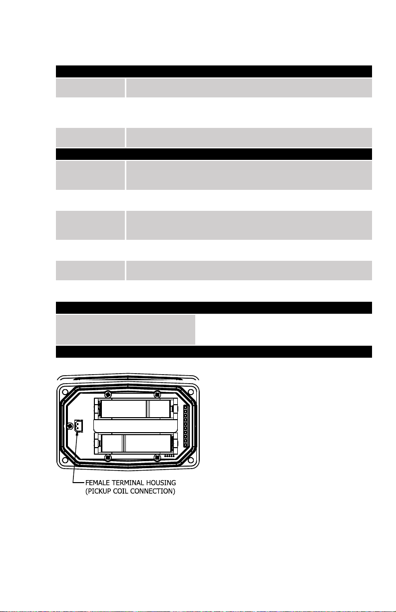
COMPUTER ELECTRONICS TERMINAL CONNECTIONS
SPECIFICATIONS
Transparent Amorphous Nylon
Operating
Temperature
Pulse
K‑Factor
Calibration
Power
(1) Factory Calibration Curve
Figure 2
If wider operating temperature ranges are desired, reference
‑40°F to +158°F (‑40°C to +70°C)
Frequency Range: 0.25 Hz – 3kHz
Minimum: ‑99.999%
Maximum: +99.999%
Yes
5
Page 6
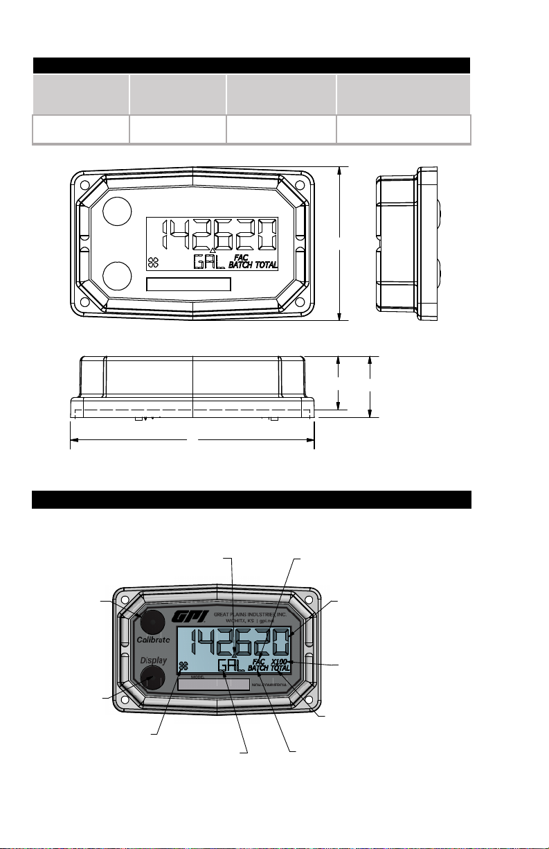
SPECIFICATIONS (CONTINUED)
DIMENSIOINS
Length
Height
Height
“C”
Width (Widest Point)
3.40 in.
(8.6 cm)
0.85 in.
(2.1 cm)
0.72 in.
(1.8 cm)
2.14 in.
(5.4 cm)
COMPUTER DISPLAY FEATURES
Figure 3
“A”
“B”
(Mounted)
“D”
D
C
B
A
Familiarize yourself with the computer features before installation and use.
CALIBRATE
BUTTON
FLOATING DECIMAL
POINT (3 PLACE)
FACTORY CALIBRATION
INDICATOR
BATCH TOTAL OR
ACCUMULATIVE TOTAL
DISPLAY
BUTTON
FLOW INDICATOR
INFORMATION ROW
BATCH INDICATOR
TOTALS SPILL-OVER
INDICATOR
(X10 OR X100)
TOTAL INDICATOR
(BATCH & ACCUMULATIVE)
Figure 4
6
Page 7

SPECIFICATIONS (CONTINUED)
AGENCY APPROVALS
Q9 Industrial Grade Computer Electronics
Intrinsically safe approval only applies when
used with a FLOMEC® FM Approved meter.
Q9 Industrial Grade Computer Electronics when installed on a
FLOMEC FM Approved meter.
IP65
NOTE: When a component with Approval Agency ratings is mated to another
SPECIFICATIONS (CONTINUED)
AGENCY APPROVALS
INTRINSICALLY SAFE FOR
CLASS I, II, III, DIV. 1,
GROUPS ABCDEFG,
T4 Ta= ‑40° to +54°C
NONINCENDIVE
FOR CLASS I, II, III, DIV. 2,
GROUPS ABCDFG, T4 Ta= ‑40° to +54°C
GREAT PLAINS INDUSTRIES, INC.,
5252 E. 36TH ST. NORTH,
WARNING:
See Owner’s
Manual for
Warnings and
Cautions Before
Installation.
WICHITA, KANSAS
67220 U.S.A
component with the same Approval Agency ratings, the combination may gain
environmental approvals.
When one of the components has lessor or no Approval Agency ratings, the resultant
combination assumes the ratings of the lessor rated component.
If one component has no ratings, the resultant combination has no ratings.
Specic Conditions of Use
1. All computer assemblies are to be used with GPI battery 902004‑02 except Q1, Q9, and R9
versions which use Energizer E92 / EN92, or Duracell MN2400 Alkaline batteries.
2. GPI remote kit assembly 113275‑1 may be used with the meter when installed in accordance
with GPI Manual No.920507‑01. GPI Remote Kit Assembly 113275‑10 may be used with the
meter when installed in accordance with GPI Manual No. 920507‑02.
3. The apparatus enclosure may contain aluminum which is considered to constitute a potential
risk of ignition by impact or friction. Care must be taken into account during installation and
use to prevent impact or friction.
REMOTE KIT ASSEMBLY (113275-10
)
4. Part of the enclosure is constructed from plastic. To prevent the risk of electrostatic sparking
the plastic surface should only be cleaned with a damp cloth.
7
Page 8

INSTALLATION
PRODUCT DESCRIPTION
INSTALLATION
This computer electronics is designed specifically for use on GPI Turbine Housings. It
is also designed to work with several accessory output modules.
The CMOS, microprocessor‑based electronics have extremely low power
requirements and data retention capabilities in both RAM and ROM. Information is
clearly displayed on a large 6‑digit LCD readout with three‑point floating decimal for
totals from .001 to 999,999 (x1), 9,999,990 (x10), or 99,999,900 (x100). All
operations are easily accessed with the two buttons on the front panel.
In a GPI turbine meter, liquid flows through the turbine housing causing an internal
rotor to spin. As the rotor spins, an electrical signal is generated in the pickup coil.
This pulse data from the turbine is translated into calibrated flow units shown on the
computer's display readout.
Before installation, ensure your computer model meets your specific needs. Refer to
the Specifications Section to confirm required features. The model number of your
computer is displayed on the outside wall of the computer housing and also inside the
computer housing on the floor of the battery holder.
If you ordered your computer electronics with a turbine body, the electronics are
installed at the factory.
If you ordered your computer separately as a replacement, simply mount the
computer on your turbine body with the four screws at the corners of the faceplate.
Make sure the seal is fully seated before tightening the screws.
If you ordered the computer with a turbine body and an accessory module, please
review and thoroughly understand all installation instructions before proceeding.
All GPI turbine meters are designed to measure flow in only one direction. The
direction is indicated by the arrow on the turbine outlet port. If the computer display is
upside down in your installation, remove the four screws, turn the display 180 degrees
and reinstall the screws. (See Figure 5)
PICKUP COIL
CONNECTOR
METER BODY
Figure 5
NOTE: When rotating the computer
display, it is not necessary to
disconnect the pickup coil connector,
however, care should be taken to
avoid inadvertent strain on the
connector wires.
8
Page 9

OPERATION
COMPUTER DISPLAY
ACTIVATE THE COMPUTER
All operations are revealed on the LCD using the large 6‑characters in the top row and
smaller characters and symbols in the second row. These characters and symbols
indicate information regarding totals, flow, calibration, units of measure and
operational messages.
Push button operation varies dependent upon the various modes of operation, i.e.
Normal Operation mode and Field Calibration mode. Their operation will be described
in their respective sections.
When batteries are installed, the computer is on continuously and always ready to
perform.
The computer is powered by field replaceable commercially available batteries.
Reference the computer maintenance section for battery replacement details.
Figure 6
Figure 7
When batteries are initially installed or
replaced, the initialization routine will start
the LCD display blank, then display
“HELLO” on the top row and “Q9Disp” on
the information row for one second. (See
Figure 6)
The LCD will then display “HELLO” on the
top row and “FW Vxx” on the information
row for one second. The Vxx will be the
version of the software installed on the
display. Example: “FW V03” indicates
firmware version 3 installed on the display.
(See Figure 7)
General
The computer maintains two totals; Batch total and accumulative total. The batch
total can be reset to measure flow during a single use. The accumulative total
provides continuous measurement and can only be reset by removing the batteries,
holding down the Display button, and replacing the batteries.
The button usage map on the next page is useful for understanding where the various
menus are located within the software programming and the route to get to a specific
menu. The map is followed by user instructions explaining each menu.
9
Page 10

OPERATION
NORMAL OPERATION MODE
Button Usage Map – Normal Operation Mode
BUTTON
Display
Display
Hold
Calibrate
Calibrate
Button Operation (Normal Operation Mode)
Toggles Between
When Batch Total
is Displayed
and
Press
Display
Hold for 3 Seconds to Enter
Field Calibration Mode
Hold for 3 Seconds
to Reset Batch Total
Toggles Between
Batch Total
Accumulative Total
Gallons
Litres
Display Button: Toggle between batch total and accumulative total.
When a total is displayed, momentarily pressing Display button toggles the top row of
large display digits between batch total and accumulative total. The information row
will change to the proper units and the corresponding icons will also be shown, i.e.
TOTAL or BATCH TOTAL. (See Figure 8)
(Batch Total‑Litres) (Accumulative Total‑Gallons)
Figure 8
10
Page 11

OPERATION (continued)
NORMAL OPERATION MODE (continued)
Display Button: Batch total reset.
When a batch total (see Figure 9‑1) is displayed, press and continue to hold Display
button for 3 seconds; the software will display a three second count down, then reset
the batch total to zero. (See Figures 9‑2 thru 9‑4)
NOTE: If Display button is released prior to
count down completion, the software returns to
Figure 9‑1
Figure 9‑2
Figure 9‑3
Figure 9‑4
NOTE: When the accumulative total is displayed in Normal Operation Mode, it cannot
be reset using the Display button. Accumulative total can only be reset by removing
Figure 9‑5
batch total screen. (See Figure 9‑1)
NOTE: After count down completes, display will
show 0.000 until user releases Display button.
(See Figure 9‑3)
NOTE: After Display button is released, the
display will return to Batch Total screen and will
increment the total if flow is detected. (See Figure
9‑4)
the batteries, holding down the Display button, and
replacing the batteries. If the user attempts to reset it
using the Display button, the software will display a
“Reset Denied” message on the LCD until the button
is released. (See Figure 9‑5).
11
Page 12

OPERATION (continued)
FIELD CALIBRATION MODE (continued)
Calibration Method Selection Menu
This menu is used to define which calibration method will be used in normal operation,
either factory calibration or field calibration. The calibration method last entered (by
the user or the factory) will be used to calculate volume.
Factory Calibration: All units are configured with a "factory" calibration. This factory
calibration (FAC icon displayed below 6-digit display) is permanently programmed into
the computer and is not user adjustable.
NOTE: The factory calibration stored in the unit will never be lost
Factory calibration is the typical use
method (see Figure 10-1). Prior to
shipping from the factory, the display will
be configured and calibrated to the meter
body on which it is installed (or going to be
installed).
When the user selects this option the FAC
icon will be “ON” to indicate that the display
is using its factory calibration table. This
method does not support field calibration.
Figure 10-1
Field Calibration: Field calibration is done using the dispense/display method.
Dispense/Display is a field calibration
method by which the user will dispense a
known volume of fluid and the software will
keep track of the pulse count during the
dispense operation. The user will then
enter the known volume into the display
and the software will calculate a K-factor
for the volume dispensed. (See Figure 10-
2)
Figure 10-2
General
The calibration method may be set by the user (either factory calibration or field
calibration). The field calibration can be modified at any time using the process
described in this section. Totals derived from the field calibration are being invoked
when the (FAC) icon is no longer visible below the 6-digit display.
Factory calibration settings are programmed into each computer during
manufacturing, using Stoddard test solvent at 70° F (21° C) for meters up to 1 inch.
Meters 1-1/2 inch and larger are factory calibrated using water at 70° F (21° C).
Settings are correct for light liquids such as water, gasoline or diesel. Readings using
the factory calibration (FAC) may not be accurate in some situations, for example,
"heavy" liquids such as motor oil, under extreme temperature conditions, non-
standard plumbing configurations or with fluids other than mentioned above.
For improved accuracy under such conditions, the computer allows for field
calibration, that is, user entry of custom calibration parameters.
12
Page 13

OPERATION (continued)
FIELD CALIBRATION MODE (continued)
Verify Accuracy before Beginning Field Calibration
For the most accurate results, dispense at a flowrate which best simulates your actual
operating conditions. Avoid "dribbling" more fluid or repeatedly starting and stopping
the flow. This can result in less accurate calibrations. Make sure you meet the
meter's minimum flowrate requirements.
Low Flow meter: 0.3 GPM (1.1 LPM or 0.25 IGPM)
1 inch meter: 3.0 GPM (11 LPM or 2.5 IGPM)
2 inch meter: 30 GPM (113 LPM or 25 IGPM)
The use of a uniformly dependable, accurate calibration container is recommended for
the most accurate results. A five gallon calibration container is available in the parts
section of this manual. For best results, the meter should be installed and purged of
air before field calibration.
Due to high flowrates on meters 2 inch and larger, it is strongly recommended that
field calibration be completed with a combination of volume and weight determined
with fine resolution scales.
Field Calibration Entry
At the beginning of the calibration entry menu, the software will allow the user to start
the calibration process or to exit back to normal operation. (See Figures 11‑1 & 11‑2)
Advance focus: Press and release the CALIBRATE button.
Advance to the next menu: Press and release the DISPLAY button.
The bottom row of characters will be in focus to indicate that the user can select
between either “Start” or “Exit” by advancing focus.
Figure 11‑1
Figure 11‑2
If “Start” is in focus when advancing to the
next menu, the software will automatically
advance to the dispense/display field
calibration menu
If “Exit” is in focus when advancing to the
next menu, the software will display a
“save” screen (see Figure 13‑3) to enter
“yes or no” to save your entries.
13
Page 14

OPERATION (continued)
FIELD CALIBRATION MODE (continued)
Dispense Display Method
Dispense/Display is a field calibration method by which the user will dispense a known
volume of fluid and the software will keep track of the pulse count during the dispense
operation. The user will then enter the known volume into the display and the
software will calculate a K-factor for the volume dispensed. (See Figure 12-1)
The software will allow the user to
dispense a known volume in order to
create a custom K-factor. This will not over
write the existing factory calibration table.
Figure 12-1
The first screen in this calibration method
will show “run 1” indicating that computer is
waiting for flow to start. (See Figure 12-2)
NOTE: Pressing any single button while
on this screen will not have any effect.
Pressing both buttons and holding will
allow the user to exit calibration mode.
Figure 12-2
Begin dispensing into a container of known
accurate volume. As soon as pulses are
detected by the software, the screen will
switch to display the volume being
dispensed on the top row and the volume
unit on the bottom row. (See Figure 12-3)
Figure 12-3
When the user is finished with the run, modify the volume on screen to be the actual
volume dispensed. To do this pressand hold the Display button until the left most
digit begins to flash indicating it is in focus, then release the Display button.
Pressing the Calibrate button will increment the digit in focus. Pressing the Display
button will advance focus to the next digit.
Holding Display and pressing Calibrate will lock in the entered volume.
The software will then calculate the K-factor for the volume entered based on the
pulse count for the run and the volume entered. The average frequency and the K-
factor will be entered into the custom user K-factor table for run 1.
14
Page 15

OPERATION (continued)
FIELD CALIBRATION MODE (continued)
Exit Dispense Display Method
This menu is used to indicate to the user they are exiting the field calibration mode
menu. The user can exit any of the calibration methods at any time. To exit, press
and hold the Display and Calibrate buttons simultaneously for 3 seconds; the
software will display a three second count down (see Figure 13-1), then reset to show
the exit display. (See Figure 13-2)
Figure 13-1
NOTE: After 3 seconds, “FldCAL” will then
be displayed on the top row and “Exit” on
the bottom row (see Figure 13-2) until the
user releases both buttons. The software
will store the sorted table of frequencies
and K-factors, then exit back to normal
mode.
Figure 13-2
COMPUTER MAINTENANCE
Batteries
The computer electronics are powered by alkaline batteries. Removing the batteries
before storing the meter will extend battery life since the computer is always on (either
standby or active) when the batteries are installed.
If the meter's readout should become dim, blank or the low battery message appears
(see below), the batteries should be replaced.
Note: If the battery life is sufficiently low,
“LOWBAT” will be displayed in the
message area on the bottom row of
characters. This low battery message will
be displayed automatically.
15
Page 16

OPERATION (continued)
COMPUTER MAINTENANCE (continued)
Battery Replacement Information
The computer is shipped with (2) alkaline AAA size batteries (1.5‑volts each) installed.
The installed batteries are Agency Approval rated for use with this electronic device.
Battery replacements are readily available as an off‑the‑shelf item. To maintain the
Agency Approvals of this device, and maintain the GPI warranty, the batteries listed
below are approved for use.
Alkaline (AAA size, 1.5‑volts each)
Energizer, Alkaline, E92 or En92
Duracell, Alkaline, Mn2400
Do not mix brands or technologies. Do not mix old and new batteries. Do not
use rechargeable batteries.
Open battery cells should be disposed of in accordance with local regulations.
When batteries are disconnected or fail, the computer memory will retain the batch
total, accumulative total, factory calibration curve, and field calibration curve
indefinitely.
It is strongly recommended that battery checks and terminal cleaning be a part of a
routine maintenance schedule. Battery terminals should be cleaned annually.
Batteries can be replaced without removing the meter from the piping system.
Replace Batteries
1. Remove the (4) corner screws attaching the computer electronics to the meter and
lift the computer electronics from the meter.
2. Remove the batteries.
3. Check the battery terminals and remove any corrosion.
4. Install the new batteries and make sure the positive posts are positioned correctly.
When the batteries are installed correctly, the computer powers on automatically
and the display will show information.
5. Make sure the seal is fully seated before placing the computer electronics back on
the turbine. Tighten the (4) screws previously removed.
6. Do not clean exterior of computer assembly with Isopropyl Alcohol.
16
Page 17

PARTS
The factory, when provided with
model number and serial number,
can replace your entire Computer
Electronics Assembly.
Order replacement kits, parts, and
accessories with the part numbers
given here.
Part No. Description
901002‑52 Seal
116000‑1 Large (5 gal.) Calibration
Container. Use for water
baseduids.Donotuse
with fuel products.
SERVICE
For warranty consideration, parts,
or other service information, please
contact your local distributor. If you
need further assistance, call the
GPI Customer Service Department
in Wichita, Kansas, during normal
business hours.
1‑888‑996‑3837
Toobtain prompt,ecient service,
always be prepared with the following
information:
1. The model number of your com‑
puter electronics.
2. The serial number or manufactur‑
ing date code of your computer
electronics.
3. Specicinformation aboutpart
numbers and descriptions.
For warranty work always be pre‑
pared with your original sales slip
or other evidence of purchase date.
Returning Parts
Please contact the factory before
returning any parts. It may be possible
to diagnose the trouble and identify
needed parts in a telephone call. GPI
can also inform you of any special
handling requirements you will need
to follow covering the transportation
and handling of equipment which has
been used to transfer hazardous or
ammableliquids.
CAUTION
Do not return computer
electronics or meters without
specic authority from the GPI
Customer Service Department.
Due to strict regulations
governing transportation,
handling, and disposal of
hazardous or ammable liquids,
GPI will not accept computer
electronics or meters for rework
unless they are completely free
of liquid residue.
CAUTION
Meters not flushed before
shipment can be refused and
returned to the sender.
17
Page 18

Declaration of Conformity
Product Name: Electronic Digital Meter
Model Numbers: 03*****
A1***********
A2***********
G2*****9***
We declare, that the product:
Model numbers include all combinations of an alpha-numeric series as illustrated above.
Conforms with the requirements of the Directives below by compliance with the Standards subsequently listed:
1. Council Directive 2004/108/EC (until April 19, 2016) and Directive 2014/30/EU (from April 20, 2016)
relating to Electro-Magnetic Compatibility.
EN 61000-6-2:2005
EN 61000-6-3:2007/A1:2011
2. Council Directive 94/9/EC (until April 19th, 2016) and Directive 2014/34/EU (from April 20th, 2016)
relating to equipment or protective systems intended for use in potentially explosive atmospheres.
EN 60079-0:2018
EN 60079-11:2012
EN 60529+A1:2000
3. Council Directive 2011/65/EU and 2002-95-EC as amended (RoHS Directive) relating to the restriction of
certain hazardous substances in electrical and electronic equipment.
Supplementary Information:
- is product meets an (Ingress Protection) IP65 rating.
- is product has insucient internal volume size or pressure ratings to meet a pressure directive.
- is product is not recommended for custody transfer or application where levying by consumption takes
place.
I the undersigned, hereby declare that the equipment specied above conforms to the above Directive(s) and
Standard(s).
Signature:
Full Name: Victor Lukic
Position: President
Great Plains Industries, Inc.
Place: Wichita, KS USA
March 2016
Notied Body: FM Approvals Europe Ltd.
One Georges Quay Plaza
Dublin, Ireland D02 E440
Identication No: 2809
EC-Type Examination Certicate No: FM13ATEX0016X
18
Page 19

Q9 Computer Electronics:
ATEX
Factory Mutual Approved
Intrinsically Safe for Class I, II, III, Division 1, All Groups
Intrinsically Safe approval only applies when used with GPI® FM Approved meter
Q9 Computer Electronics when installed on a GPI FM Approved meter
ATEX
IP65
Factory Mutual Approved
Intrinsically Safe for Class I, II, III, Division 1, All Groups
19
Page 20

Limited Warranty Policy
Great Plains Industries, Inc. 5252 E. 36th Street North, Wichita, KS USA 67220‑3205,
hereby provides a limited warranty against defects in material and workmanship on all
products manufactured by Great Plains Industries, Inc. This product includes a 2 year
warranty. Manufacturer’s sole obligation under the foregoing warranties will be limited
to either, at Manufacturer’s option, replacing or repairing defective Goods (subject
to limitations hereinafter provided) or refunding the purchase price for such Goods
theretofore paid by the Buyer, and Buyer’s exclusive remedy for breach of any such
warranties will be enforcement of such obligations of Manufacturer. The warranty shall
extend to the purchaser of this product and to any person to whom such product is
transferred during the warranty period.
The warranty period shall begin on the date of manufacture or on the date of purchase
with an original sales receipt. This warranty shall not apply if:
A. theproducthasbeenalteredormodiedoutsidethewarrantor’sdulyappointed
representative;
B. the product has been subjected to neglect, misuse, abuse or damage or has
been installed or operated other than in accordance with the manufacturer’s
operating instructions.
To make a claim against this warranty, contact the GPI Customer Service Department
at 316‑686‑7361 or 888‑996‑3837. Or by mail at:
If you are outside North or South America contact:
The company shall, notify the customer to either send the product, transportation prepaid,
tothecompanyatitsoceinWichita,Kansas,ortoadulyauthorizedservicecenter.
The company shall perform all obligations imposed on it by the terms of this warranty
within 60 days of receipt of the defective product.
GREAT PLAINS INDUSTRIES, INC., EXCLUDES LIABILITY UNDER THIS WAR‑
RANTY FOR DIRECT, INDIRECT, INCIDENTAL AND CONSEQUENTIAL DAMAGES
INCURRED IN THE USE OR LOSS OF USE OF THE PRODUCT WARRANTED
HEREUNDER.
Thecompanyherewithexpresslydisclaimsanywarrantyofmerchantabilityortness
for any particular purpose other than for which it was designed.
Thiswarrantygivesyouspecicrightsandyoumayalsohaveotherrightswhichvary
from U.S. state to U.S. state.
Note: In compliance with MAGNUSON MOSS CONSUMER WARRANTY ACT – Part
702 (governs the resale availability of the warranty terms).
Great Plains Industries, Inc.
5252 E. 36th St. North
Wichita, KS, USA 67220‑3205
Great Plains Industries – Australia
1/16 Atkinson Road,
Taren Point NSW 2229, Sydney, Australia
ATEX
920787-01 Rev H 11/02/2020
(IP65)
© 2020 Great Plains Industries, Inc., All Rights Reserved.
Great Plains Industries, Inc. / 800-835-0113 / GPI.net
 Loading...