

Page 1
Automatic Level
NP-732
INSTRUCTIONS FOR USE
Page 2
- 1 -
Contents
Before use…………………………………………………2
1.Nomenclature.………………………………………………3
2.Operation…………………………………...……………….4
2-1 Preparing before surveying……………………….……….….4
2-2 Surveying method………….…………...………...……..…….5
2-2-1 Measuring altitude difference……………………………..….5
2-2-2 Measuring horizontal angle…………………………………..7
2-2-3 Measuring distance using the stadia lines…………..……….7
3.Regular checking/ adjusting………………………..……..……9
3-1 Checking and adjusting of the circular level……………..…9
3-2 Checking of the compensator………………………………...10
3-3 Checking of i angle…………………………………….….....10
4.Parameter and technical index……………………………12
5.Standard configuration………………...………………….12
NP-732 SERIES
Page 3
- 2 -
Before use
1 Operation
1) The NP-732 series automatic level is a precision instrument. Handle
it carefully according to the engineering measurement regulations,
and keep it away from heavy shocks and vibration.
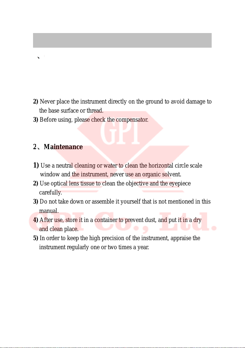
2) Never place the instrument directly on the ground to avoid damage to
the base surface or thread.
3) Before using, please check thecompensator.
2 Maintenance
1) Use a neutral cleaning or water to clean the horizontal circlescale
window and the instrument, never use an organic solvent.
2) Use optical lens tissue to clean the objective and the eyepiece
carefully.
3) Do not take down or assemble it yourself that is not mentioned in this
manual.
4) After use, store it in a container to prevent dust, and put it in a dry
and clean place.
5) In order to keep the high precision of the instrument, appraise the
instrument regularly one or two times a year.
NP-732 SERIES
Page 4
- 3 -
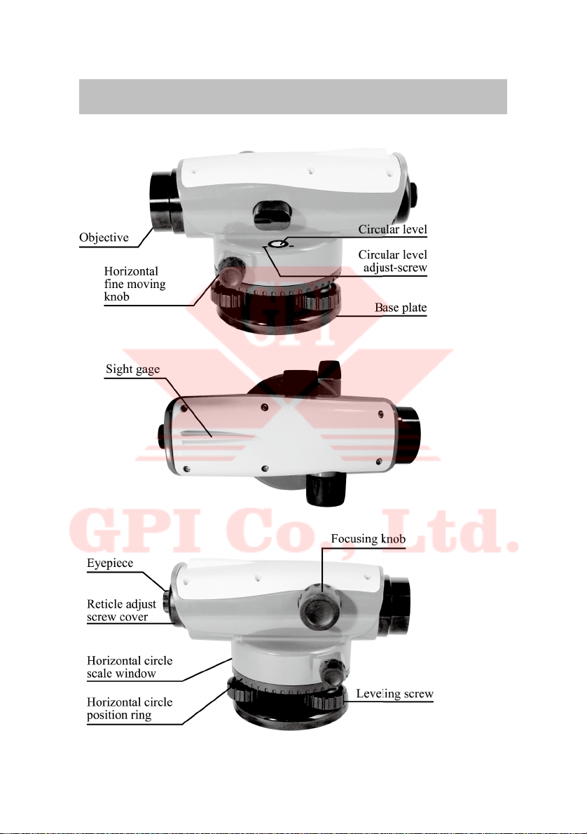
1. Nomenclature
NP-732 SERIES
Page 5
- 4 -
2.Operation
2-1 Preparing before surveying
(1) Spread the tripod-legs so that the leg-tips form a regular triangle.
Extend the legs until the tripod head is roughly at 10cm lower than
your eye level and then fasten the extension clamp screws.
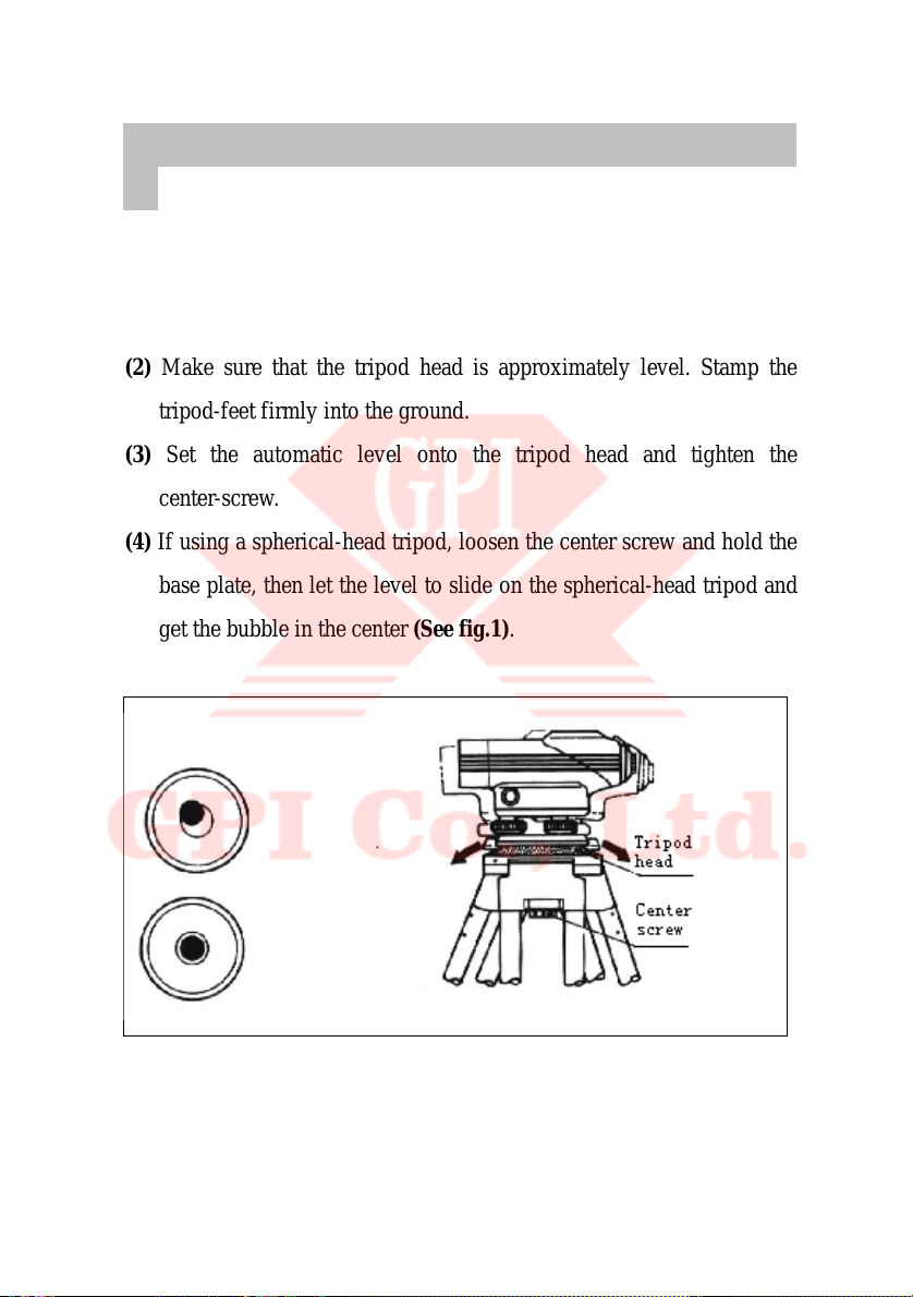
(2) Make sure that the tripod head is approximately level. Stamp the
tripod-feet firmly into the ground.
(3) Set the automatic level onto the tripod head and tighten the
center-screw.
(4) If using a spherical-head tripod, loosen the center screw and hold the
base plate, then let the level to slide on the spherical-head tripod and
get the bubble in the center (See fig.1).
(5) Fasten the center-screw.
(6) Adjust the three leveling screws to get the bubble in the center (See
fig.2).
Fig.1
NP-732 SERIES
Page 6

- 5 -
2.Operation
(7) Adjust the eyepiece until the image of the reticle is clear.
(8) Aim the objective at the staff through the sight gage of the
instrument.
(9) Turn the focusing knob to get the staff image very clear. Shift your
eyes around in the field of view and make sure that there is no
displace between the reticle and the staff, then the surveying and
reading can be done. Adjust horizontal fine moving knob to aim the
telescope at the target.
2-2Surveying method
2-2-1Measuring altitude difference
(1) Set up the instrument at a point approximately halfway between
points A and B. (See fig.3)
Fig.2
NP-732 SERIES
Page 7

- 6 -
2.Operation
(2) Set up the staff vertically at point A, and take the reading a
(backsight).
(3) Set up the staff vertically at point B, and take the reading b
(foresight).
(4) The altitude difference h from B to A is h=a-b.
(5) If the distance between A and B is too long, or the altitude
difference from B to A is too large, divide the distance into some
regions, then carry on measuring in each region. (See fig.4)
Fig.3
Fig.4
NP-732 SERIES
Page 8

- 7 -
2.Operation
Calculation of altitude difference as follow:
Altitude difference=Sum of backsight-Sum of foresight
Altitude of the surveying point=Altitude of known point+Altitude
difference
2-2-2Measuring horizontal angle
The horizontal-circle-scale is graduated in minimum value of 1°and
numbered every 10°.
(1)Use the plumb-bob to set the center of the instrument right above the
surveying point.
(2)Aim the telescope at point A and set the horizontal-circle-scale to 0°
by turning the horizontal circle positing ring.
(3)Aim the telescope at point B and take the angle reading. It’s the angle
of position between A and B.(See fig.5)
2-2-3Measuring distance using the stadia lines
Using the top and bottom stadia lines on the reticle, the distance
between the center of the instrument and the staff can be measured
approximately. Aim the telescope at the staff, read the number of
Fig.5
NP-732 SERIES
Page 9

- 8 -
2.Operation
centimeters on the staff between two stadia lines, then transform it
into number of meter by multiplying 100, and the number of meter is
the distance between the center of instrument and the staff. (See fig6)
Fig.6
NP-732 SERIES
Page 10

- 9 -
3.Regular checking /adjusting
3-1 Checking and adjusting of the circular level
(1)Adjust the leveling screws to center the bubble in the circular level.
(2)Turn the instrument 360°. If the bubble is still in the center, it means
that the circular level is workable.
(3)If the bubble shifts away from the center, please adjust according to
following methods:
Move the bubble one half of the shift to the center of the circular level
by adjusting the leveling screws. Then get the bubble in the center of
the circular level by adjusting the circular level adjust-screw with the
hexagonal wrench. Repeat the above checking and adjusting, until the
bubble does not shift when the instrument turns to any direction. (See
fig.7)
3-2 Checking of the compensator
(1)Center the bubble in the circular level, and aim the telescope at a
target about 70m away.
(2)Turning the leveling screws to make the bubble slide out about 1/4 of
the circular to any direction, if there is no deviation between the image
of target and the horizontal cross-lines, it means that the working range
Fig.7
NP-732 SERIES
Page 11

- 10 -
3.Regular checking/adjusting
and the precision of the compensator are stable. This checking must be
done before surveying.
3-3 Checking of i Angle
(1)Set up the instrument at a point halfway between points A and B, the
distance between staff A and staff B is about 50mm. Take reading a1
and b1. (See fig8)
(2)Set up the instrument at a point 2m from point A. Take the reading a2
and b2. (See fig.9)
Calculate: b2′=a2-(a1-b1), If b2′= b2, it means that the instrument is
workable, otherwise adjust the instrument as follows:
Unscrew and remove the cover for the reticle adjusting screw. (See
fig.10)
Use the adjusting pin to adjust the position of the cross line of reticle,
if b2′ b2, adjust downwards, otherwise, adjust upwards.(See fig11)
Repeat the adjustment until b2′= b2 or the difference is smaller than
4mm.
NP-732 SERIES
Page 12

- 11 -
3.Regular checking/adjusting
Fig.8
Fig.9
Fig.10
Fig.11
NP-732 SERIES
Page 13

- 12 -
4.Parameter and technical index
NP-732 Series(A model, B model)automatic level technical parameter
5.Standard configuration
Instrument Downy cloth Plumb bob
Incidental tool Operation manual Plastic case
Parts
Model
NP-732
Magnification
32X
Image
Erect image
Objective aperture
≥42mm
Min focusing distance
0.3m
Stadia multiplication
constant
100
Stadia additive constant
0
Resolution
≤4″
Telescope
Pattern of stadia reticle
Working range
±15′
Compensating error
≤±0.3″/1′
Compensa
-tor
Setting accuracy
≤±0.5″
Scale graduation range
360°/400g
Scale
Scale minimum value
1°/lgon
Sensitivity of circular bubble
8′/2mm
Base screw
M16 or 5/8″for option
Environmental temperature
-25℃ -+50℃
Carry case
Plastic case(Aluminum case for potion with extra
Parallel plate micrometer
Available for option
NP-732 SERIES
NP-732 SERIES
Page 14

Giant Precision Instrument Co., Ltd.
No.16, Ln. 134, Liancheng Rd., Zhonghe Dist., New Taipei City 235, Taiwan
TEL 886-2-2246-7302 FAX 886-2-2246-7301
 Loading...